Page is loading ...

LP & HIGH ALTITUDE LP GAS CONVERSION KIT
FOR INSTALLATIONS IN THE UNITED STATES (0 -7,000 FT)
INSTALLERS: Please read all instructions before converting
the furnace. Pay attention to all safety warnings and any other
special notes highlighted in the manual. Safety markings are
used frequently throughout this manual to designate a degree
or level of seriousness and should not be ignored. WARNING
indicates a potentially hazardous situation that if not avoided,
could result in personal injury or death. CAUTION indicates a
potentially hazardous situation that if not avoided, may result in
minor or moderate injury or property damage
This conversion kit is only to be used to convert a natural gas
unit to LP/Propane gas or to an LP high altitude application in
the United States. This kit may only be used in units installed
in altitudes between zero and 7,000 feet above sea level. For
installations in Canada, the Canadian conversion instructions
must be used.
IMPORTANT NOTE: DO NOT REMOVE OR DEFACE THE
ORIGINAL RATING PLATE.
This conversion kit is backwards compatible with (*)R4(M,N)
& R6GN (150-180 Model) units. Contact NORDYNE Technical
Services for more information on these appliances.
Table 1 is a detailed listing of components required for converting
light commercial units to LP Gas for altitudes between 0 & 7,000
feet. Please check the contents of the conversion kit with that of
the parts listing, and familiarize yourself with each component.
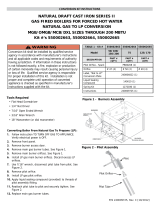
FOR (*)R4(M,N) & R6GN (150 / 180 MODELS) LIGHT COMMERCIAL PACKAGE GAS / ELECTRIC UNITS
Table 1. Conversion Kit Contents
DESCRIPTION QTY
Gas Valve (Nordyne P/N 624695)
(White Rodgers P/N 36H64-463B1)
1
Main LP Burners
7
White Rodgers Conversion Kit #F0092-1008
Converts Nordyne Valve - P/N 624695 (36H64-463B1)
1
#49 Drill Size Burner Orifice Kit (Contains 7)
1
#50 Drill Size Burner Orifice Kit (Contains 7)
1
#51 Drill Size Burner Orifice Kit (Contains 7)
1
Conversion Warning Label - P/N 703935
1
Conversion Information Label - P/N 710005
1
Installation Instructions - P/N 708393
1
The installer performing this work assumes all responsibility for this
conversion. These instructions are primarily intended to assist qualified
individuals experienced in the proper installation of these components.
Some local codes require licensed installation/service personnel for this
type of equipment. Safety should always be the deciding factor when
installing this product and using common sense plays an important role
as well. Improper installation of the components or failure to follow safety
warnings could result in serious injury, death, or property damage. After
completing the installation, return these instructions to the Homeowner’s
Package for owner-user’s future reference.
RISQUE D’INCENDIE OU D’ EXPLOSION
fournisseur de gazstaller, service agency or the gas
QUE FAIRE S’IL Y A UNE ODEUR DE GAZ
lettre les instructions du fournisseur de gaz.
AVERTISSEMENT
DO NOT DESTROY THIS MANUAL. KEEP IN A
SAFE PLACE FOR FUTURE REFERENCE.
FIRE OR EXPLOSION HAZARD
WHAT TO DO IF YOU SMELL GAS
in your building.
WARNING:
INSTALLATION INSTRUCTIONS

2
WARNING:
WARNING:
edition of the Canadian Electrical Code (CSA
1. Set the thermostat to the OFF position, or its lowest temperature
setting.
2. Shut OFF the gas supply at the manual shutoff valve located
outside of the appliance.
3. Turn off all electrical power to the appliance.
4. Remove the louvered burner access panel.
5. Move the gas valve ON/OFF knob to the OFF position. See
Figure 2 (page 5)
1. STOP! Read all the steps in the “Before you Convert the Unit”
section.
2. Remove the Burner Access Panel louvered door and open
the Motor Access panel.
3. Remove Safety Control Access Panel located above burner
assembly.
4. Disconnect the Red flame sensor wire, the two Blue flame
roll-out switch wires, and the spark ignitor wire at the burner
box
5. Remove the White wire from the LOW (M) terminal, the Brown
wire from the HI terminal, and the Black wire from the Common
(C) terminal of the gas valve.
6. Using two wrenches remove supply gas line, gas valve, and
factory gas piping back to the manifold elbow. DO NOT ALLOW
7. Remove the four (4) fasteners that secure the gas manifold
to the burner box, as shown in Figure 1. Carefully remove the
gas manifold assembly from the burner box. NOTE: The gas
manifold consists of the gas manifold and the orifices.
8. Carefully remove the burner orifices from the gas manifold,
as shown in Figure 1.
9. Remove the four fasteners that secure the burner box to the
heat exchanger mounting panel, as shown in Figure 1.
10. Carefully remove the burners from the mounting bracket
and set screws aside for later use. Note the alignment of
the burners for reassembly purposes.
NOTE: Care should be taken to ensure no damage occurs to
the spark ignitor, flame sensor, or roll out limit switch.
CONVERTING TO LP / PROPANE GAS
1. Examine the rating plate of the unit to determine Model number
and rated input (Btu/hr).
2. Count the number of burners in the burner box. Verify all
information in Table 2 (page 6) to determine the appropriate
LP gas orifice size for your application.
3. Install the appropriate LP gas burner orifices into the gas
manifold.
NOTE: The size of the new orifices that will be installed into
the unit will depend upon the type of conversion (sea level
or high altitude). Please refer to the high altitude deration
section and Table 2 (page 6) for more details on your particular
conversion.
WARNING:
injury, or death.
WARNING:
WARNING:
connections.
(*)R4G(M,N) & R6GN-150 / 180 Series
Gas Valve
Burner
Orifices
Flame
Sensor
Gas Manifold
Fasteners
Burners
Burner
Box
Spark
Ignitor
Fasteners
On/Off
Lever
Flame Roll-Out
Switch

3
HIGH ALTITUDE DERATION
High altitude application with this unit depends on the installation
altitude and the heating value of the gas. At high altitudes, the
heating value of natural gas is always lower than the heating
value at sea level.
All installations of this equipment must be made in accordance
with the National Fuel Gas Code or with local jurisdiction codes.
For installations at altitudes 2,000 feet or below, the installer does
not need to derate the heat exchanger performance.
WARNING:
IMPORTANT NOTES:
• Table2liststhecorrectoricesizetouseatdifferent
altitudes. See Installation Example 1 to determine the
unit rating and orifice size.
• Afterchangingtheorices,itisrequiredthatyoumeasure
the gas input rate by clocking the gas meter and using
the local gas heating value. See Verifying & Adjusting
the Firing Rate (page 4).
IMPORTANT NOTE: Observe the action of the
EXAMPLE 1:
Elevation: ....................................................3,890 feet
.......................................... Propane Gas
Unit Model: ................................... R6GN-150C180C
At 4,000 feet, the unit needs to be derated by 4% for each
1,000 feet of elevation. This equates to 16% or less than the
sea level rating of 153,000 Btu/h.
1. Determine unit input rating:
[153k x (100-16)%] = 129,000 Btuh. The required
heating rate for 3,890 feet is 129,000 Btu/h.
2. Determine orifice size:
From Table 2 (page 6), find the Unit Model Number.
Follow across the row and stop at the 2,001 - 4,000
elevation column. For this example, the orifice size
displayed is #50. For units equipped with a White-
Rodgers gas valve, install one #50 orifice in every
burner and check the firing rate. In this example, the
firing rate must not exceed 129,000 Btu/h.
IMPORTANT NOTES:
the High altitude deration instructions.
4. Replace factory burners with the new L.P. burners supplied in
this kit. Check burner and carryover alignment (on the burner
carryover bar), then fasten securely using all screws removed
in Step 9.
5. Reinstall burner box assembly to heat exchanger panel using
the four fasteners removed in Step 9.
6. Install manifold pipe with new LP orifices onto the burner box
assembly using four fasteners removed in Step 7. Make sure
all orifices are aligned into the burners.
NOTE:To complete the conversion from natural gas to LP
gas, the main gas valve must be replaced. Main gas valve
(#624695), White Rodgers Model # 36H6A must be used.
7. Using two wrenches, carefully reinstall the factory gas piping
and new LP Gas Valve to the manifold elbow. DO NOT ALLOW
. Make sure a leak
tight seal using joint compound approved for LP gas or other
equivalent approved methods. Secure the gas valve and piping
assembly using existing unit clamp.
8. Upon completion of the installation, inspect the alignment of
the burners with the heat exchanger tubes. The center of the
burners should be aligned with the center of the tubes.
9. Reconnect the main gas piping to the gas valve.
10. Reconnect wiring to the gas valve terminals. White wire to
Low (M), Brown wire to HI, and the Black wire to Common
(C).
11. Reconnect the spark ignitor wire to the spark ignitor.
12. Reconnect the red flame sensor wire to the flame sensor
and two blue wires to the flame roll-out switch.
PRESSURE GAUGE INSTALLATION
For LP Gas installations: Refer to the unit rating plate to determine
the incoming gas maximum and minimum inlet pressures. The
incoming gas line pressure at the gas valve inlet must be between
11.0” WC and 14.0” WC.

4
EXAMPLE 2:
• Forahighreowrateof68cu.ft.gasperhour.
• LocalheatingvalueofLPgas(obtainedfromgas
supplier) = 2,500 Btu per cu. ft.
• Inputrate=2,500x68=170,000Btuh.
LIGHTING & ADJUSTMENT OF
THE APPLIANCE
1. Turn ON the gas at the manual valve, outside of the unit.
2. Check all gas connections for leaks with a soap and water
solution. If the solution bubbles, there is a gas leak which
must be corrected.
3. Turn ON the electrical power to the appliance.
4. Move the gas valve lever/switch/knob to the ON position. See
Figure 2 (page 5). NOTE: The lever/knob must be moved to
the end of its range of motion to insure the valve is completely
open. Use only your hand to push in or turn the gas control
valve. Never use tools.
5. Set the room thermostat to a point above room temperature
to begin the heating cycle of the unit.
6. Check that the unit ignites and operates properly. Refer to the
installation instructions provided with your unit for the normal
operating sequence.
7. After the flame ignites, visually inspect the burner assembly
to ensure that the flame is drawn directly into the center of the
heat exchanger tube. The end of the flame will be out of sight
around the bend of the heat exchanger tube. In a properly
adjusted burner assembly, the flame color should be blue
with some light yellow streaks near the outer portions of the
flame.
NOTE: Until all of the air is bled out of the gas line, the spark
ignitor may not ignite the gas. If the ignition control locks out, turn
the thermostat to its lowest setting and wait one minute then turn
the thermostat to a point above room temperature. The ignitor
will try again to ignite the main burners. This process may have
to be repeated several times before the burners will ignite. After
the burners are lit, check all gas connections for leaks again with
the soap and water solution. If the solution bubbles, there is a
gas leak which must be corrected. Do not use an open flame
to check for gas leaks.
VERIFYING & ADJUSTING FIRING RATE
The input firing rate must be verified for each installation to
prevent over-firing of the unit.
CAUTION:
Do not re-drill the burner orifices. If the orifice size
• Forinstallationsat2,000feetandless,theringrate
is the same as shown on the unit rating label.
• Forinstallationsabove2,000feet,calculatethecorrect
firing rate as shown in Example 1.
• Table2(page6)liststhecorrectoricesizetouseat
different altitudes. See Example 1 to determine the unit
rating and orifice size.
• After changing the orices, it is required that you
measure the gas input rate by clocking the gas meter
and using the local gas heating value. See Step 6 and
Example 2 below.
• Observetheactionoftheburners.Makesurethereis
no yellowing, lifting or flashback of the flame.
WARNING:
1. Obtain the gas heating value from the gas supplier (HHV).
2. Verify that the gas supply line is at the correct supply pressure
and that the supply pressure is within the allowable unit limits
listed on the unit rating plate.
3. Shut off all other gas fired appliances.
4. Start the unit in heating mode and allow it to run for at least
three minutes.
5. Using an in-line flow meter, measure the gas flow rate through
the supply line to the unit. Convert the reading into cubic feet
per hour. Refer to the meter manufacturer’s instructions, or
the gas supplier for more information.
6. Multiply the gas flow rate in cubic feet per hour by the heating
value of the gas in Btu per cubic foot to obtain the firing rate in
Btu per hour. See Example 2 below.
CHECKING THE MANIFOLD PRESSURE
The manifold pressure can be measured by installing a pressure
gauge or U-tube manometer to the OUTLET end of the gas
valve as follows:
1. Turn off all electrical power to the appliance.
2. Shut OFF the gas supply at the manual shutoff valve located
outside of the appliance.
3. Using a 3/16” Allen wrench, remove the manifold pressure tap
plug located on the outlet side of the gas valve. See Figure
2 (page 5).
4. Install an 1/8” NPT pipe thread fitting, that is compatible with
a Manometer or similar pressure gauge.
5. Connect the Manometer or pressure gauge to the manifold
pressure tap. Turn gas supply on at manual shutoff.
6. Set the room thermostat above room temperature to start the
furnace.
7. Allow the unit to operate for 3 minutes and then check the
manifold pressure. For LP gas installations, the manifold
pressure should be set to approximately 9.5” WC. If the manifold
pressure is not set to the appropriate pressure, then it must
be adjusted.
ADJUSTING THE MANIFOLD PRESSURE
NOTE 1: The new valve LP regulator springs must be adjusted
to the proper input firing rates or manifold settings. Both HIGH
and LOW fire inputs should be checked. Always inspect the unit
rating label to determine the correct (0-2,000 ft) factory setting.
See Table 4 (page 6).

5
NOTE 2: The unit firing rate should be inspected for each
installation as described in these instructions. The manifold
pressure may be different than the factory setting. If the
determination of the actual unit firing rate cannot be made with
quality instruments, then the manifold pressure should be set to
the factory setting shown on the unit rating label for installations
between 0 & 2,000 ft.
(12 1/2 - 15 Ton Units):
1. Remove the protective cap from the top of the High fire gas
valve regulator as shown in the manufacturers instructions.
2. Set the manifold pressure to the factory settings, as shown
on the unit rating label – or to the correct manifold pressure
setting to obtain the correct firing rate.
NOTE: Turn the adjusting screw clockwise to increase pressure
or counterclockwise to reduce pressure. To prevent the screw
from backing all the way out from the valve, turn the screw slowly.
3. Replace the protective cap over the adjustment screws and
tighten.
NOTE: The unit Low firing rate (Stage 1 only) should be approx.
65% of the unit High firing rate. (Stage 1 & 2) See Table 2.
From example 1 (page 3): The furnace high fire rating of 129,000
Btuh reduced for 4,000 ft. elevation, would have a low fire rating
of 84,000 Btuh, or 0.65 x 129,000 Btuh.
4. Inspect the unit low firing rate in the same manner described
in the instructions for Verifying & Adjusting Firing Rate section
(Page 4).
5. Use the same procedure for the High fire adjustment described
in steps 1-3 above to adjust the Low fire manifold pressure. If
the firing rate cannot be determined, set the low fire manifold
pressure to the factory setting as shown on the unit rating
label, or refer to table 4.
REMOVING THE PRESSURE GAUGE
After the manifold pressure has been properly adjusted, the
pressure gauge or U-tube manometer must be removed from
the gas valve.
1. Turn the thermostat to its lowest setting.
2. Shut OFF the main gas supply to the unit at the manual shut-
off valve, located outside of the unit.
3. Shut OFF all electrical supplies to the unit.
4. Remove the manometer adapter from the gas valve and
replace it with the 1/8” NPT manifold pressure plug removed
earlier. Verify the plug is sealed tightly and not cross threaded.
5. Turn ON all electrical power to the unit.
6. Turn ON the main gas supply to the unit at the manual shut-
off valve, located outside of the unit.
COMPLETING THE CONVERSION
1. For all (*)R4(M,N) or R6GN-150 / 180 conversions to LP gas,
affix the conversion warning label (#703935) provided in the
kit to the outside of the units louvered burner access panel.
Next, affix the conversion information label (#710005) over
the Natural Gas warning label. Each label shall be prominent
and visible after installation.
2. Affix the gas valve manufactures labels to the valve as
described in the manufactures instructions.
3. Replace the unit’s louvered burner access panel.
4. Run the appliance through a complete cycle to assure proper
operation.
LOW REGULATOR COVER SCREW
(TWO STAGE ONLY)
REGULATOR ADJUST SCREW
REGULATOR SPRING
PILOT COVER SCREW
PILOT GASKET
PILOT ADJUST SCREW
REGULATOR SPRING
REGULATOR ADJUST SCREW
SINGLE STAGE AND TWO STAGE
HIGH REGULATOR COVER SCREW
MANIFOLD PRESSURE
TAP (OUTLET)
P/N - 624695
Model 36H64
IMPORTANT NOTE: When converting to LP/
1. Remove both regulator cover screws. See Figure 3.
2. Remove both regulator adjustment screws from the gas
valve (located beneath the cover screws).
3. Remove both Natural Gas regulator springs (color coded
silver / Plain) from the regulator sleeves.
4. Install both L.P. regulator springs (provided in the
conversion kit and color coded white) into the regulator
sleeves.
5. Replace the HIGH regulator adjustment screw and adjust
approximately 12 turns to the bottom stop.
6. Relace the LOW regulator adjustment screw and adjust
approximately 8 turns.
7. Check and adjust both regulator settings (High and Low
fire) to the firing rates listed in Table 3 for factory settings
below 2,000 ft elevation or for reduced firing rates based
on final high altitude calculations
Inlet
Pressure
Ta p
Model 36H64
Manifold
Pressure
Tap (Outlet)
ON/OFF
Switch

6
Unit
Model
Gas
of
Gas
Valve
Manufacturer
Orifice Size for Increased Elevation
(Above Sea Level)
High Fire
0 to
2,000 Ft
2,001 FT
to
4,000 Ft
4,001 FT
to
6,000 Ft
6,001 FT
to
7,000 FT
(*)R4G(M,N) or
R6GN-XXX*-180C
L.P.
4
White
Rodgers
153,000 122,000 100,000 80,000 49 50 51 51
(*)R4G(M,N) or
R6GN-XXX*-270C
6 230,000 184,000 149,000 119,000 49 50 51 51
(*)R4G(M,N) or
R6GN-XXX*-315C
7 268,000 214,000 174,000 139,000 49 50 51 51
NOTE: Refer to Instructions for High Altitude Deration to determine heat-exchanger capacity at increased elevations.
Unit
Model
Gas
Heating
(High Fire)
Heating
(High Fire)
Heating
Rise
Range (°F)
CFM / Rise Range (1) - High Fire Data
(*)R4G(M,N) or
R6GN-150
(
†)
-180C
L.P.
153,000 122,000 20 - 50
4000 4600 5200 5600 SCFM
19 17 16 15 14 13 LF-Rise (° F)
28 26 25 23 22 20 HF-Rise (° F)
(*)R4G(M,N) or
R6GN-150
(
†)
-270C
230,000 184,000 30 - 60
4000 4600 5200 5600 SCFM
28 26 24 22 21 20 LF-Rise (° F)
43 40 37 35 33 30 HF-Rise (° F)
(*)R4G(M,N) or
R6GN-180
(
†)
-270C
230,000 184,000 30 - 60
4800 5000 5200 5400 5700 6000 SCFM
23 22 21 20 19 18 LF-Rise (° F)
35 34 33 32 30 28 HF-Rise (° F)
(*)R4G(M,N) or
R6GN-180
(
†)
-315C
268,000 214,000 30 - 60
4800 5000 5200 5400 5700 6000 SCFM
27 26 25 24 23 21 LF-Rise (° F)
41 40 38 37 35 33 HF-Rise (° F)
NOTE: (1) Temperature rise data is approximate and based on unit installations of 2,000 feet or less.
LF=Low Fire, HF=High Fire
Gas
Valve
Manufacturer
Gas
Valve
Model No.
Inlet
Pressure
(
†)
Inlet
Pressure
(
†)
Factory Set
Manifold
Pressure
(
†)
High Fire
Factory Set
Manifold
Pressure
(
†)
(*)R4G(M,N) or R6GN-XXX*-180C
White
Rodgers
36H64
14.0 (3.49) 11.0 (2.74)
9.5 (2.37) 5.0 (1.24)
(*)R4G(M,N) or R6GN-XXX*-270C
(*)R4G(M,N) or R6GN-XXX*-315C
NOTE:
† Pressure values are expressed in: in-WC (kPa)
Table 4. Unit / Valve data - LP gas only

7

(Replaces 7083930)
Specifications & illustrations subject to change without notice or incurring obligations (06/15).
O’Fallon, MO, © Nortek Global HVAC LLC 2015. All Rights Reserved.
/