Epson L360 User manual

Category
Print & Scan
Type
User manual
SERVICE MANUAL
CONFIDENTIAL
Color Inkjet Printer
L365/L366, L360/L362/L363
L310/L312/L313,L220/L222, L130/L132
SEMF14-013
Confidential
Notice:
All rights reserved. No part of this manual may be reproduced, stored in a retrieval system, or transmitted in any form or
by any means, electronic, mechanical, photocopying, recording, or otherwise, without the prior written permission of
SEIKO EPSON CORPORATION.
All effort have been made to ensure the accuracy of the contents of this manual. However, should any errors be
detected, SEIKO EPSON would greatly appreciate being informed of them.
The contents of this manual are subject to change without notice.
The above not withstanding SEIKO EPSON CORPORATION can assume no responsibility for any errors in this
manual or the consequences thereof.
EPSON is a registered trademark of SEIKO EPSON CORPORATION.
Note :Other product names used herein are for identification purpose only and may be trademarks or registered
trademarks of their respective owners. EPSON disclaims any and all rights in those marks.
Copyright ©
2015 SEIKO EPSON CORPORATION
Printer CS Quality Assurance Department
Confidential
Safety Precautions
All safety procedures described here shall be strictly adhered to by all parties servicing and maintaining this
product.
DANGER
Strictly observe the following cautions. Failure to comply could result in serious bodily injury or loss of life.
1. Always disconnect the product from the power source and peripheral devices when servicing the product or
performing maintenance.
2. When performing works described in this manual, do not connect to a power source until instructed to do so.
Connecting to a power source causes high voltage in the power supply unit and some electronic components
even if the product power switch is off. If you need to perform the work with the power cable connected to a
power source, use extreme caution to avoid electrical shock.
WARNING
Strictly observe the following cautions. Failure to comply may lead to personal injury or loss of life.
1. Always wear protective goggles for disassembly and reassembly to protect your eyes from ink in working. If
any ink gets in your eyes, wash your eyes with clean water and consult a doctor immediately.
2. When using compressed air products; such as air duster, for cleaning during repair and maintenance, the use
of such products containing flammable gas is prohibited.
PRECAUTIONS
Strictly observe the following cautions. Failure to comply may lead to personal injury or damage of the product.
1. Repairs on Epson product should be performed only by an Epson certified repair technician.
2. No work should be performed on this product by persons unfamiliar with basic safety knowledge required for
electrician.
3. The power rating of this product is indicated on the serial number/rating plate. Never connect this product to
the power source whose voltages is different from the rated voltage.
4. Replace malfunctioning components only with those components provided or approved by Epson;
introduction of second-source ICs or other non-approved components may damage the product and void any
applicable Epson warranty.
5. The capacitors on the Main Board may be electrically charged right after the power turns off or after driving
motors which generates counter electromotive force such as when rotating the PF Roller or when moving the
CR Unit. There is a risk to damage the Main Board if the Head FFC is short-circuited with the capacitors on
the Main Board electrically charged, therefore, after the power turns off or after motors are driven, leave the
printer untouched for approximately 30 seconds to discharge the capacitors before starting disassembly/
reassembly.
6. To prevent the circuit boards from short-circuiting, be careful about the following when handling FFC or
cables.
When handling FFC, take care not to let the terminal section of FFC touch metal parts.
When connecting cables/FFC to the connectors on circuit boards, connect them straight to the connectors to avoid
slant insertion.
Confidential
7. In order to protect sensitive microprocessors and circuitry, use static discharge equipment, such as anti-static
wrist straps, when accessing internal components.
8. Do not tilt this product immediately after initial ink charge, especially after performing the ink charge several
times. Doing so may cause ink to leak from the product because it may take some time for the waste ink pads
to completely absorb ink wasted due to the ink charge.
9. Never touch the ink or wasted ink with bare hands. If ink comes into contact with your skin, wash it off with
soap and water immediately. If you have a skin irritation, consult a doctor immediately.
10. When disassembling or assembling this product, make sure to wear gloves to avoid injuries from metal parts
with sharp edges.
11. Use only recommended tools for disassembling, assembling or adjusting the printer.
12. Observe the specified torque when tightening screws.
13. Be extremely careful not to scratch or contaminate the following parts.
Nozzle plate of the Printhead
CR Scale
PF Scale
Coated surface of the PF Roller
Gears
Rollers
Scanner Sensor
Exterior parts
14. Never use oil or grease other than those specified in this manual. Use of different types of oil or grease may
damage the component or give bad influence on the printer function.
15. Apply the specified amount of grease described in this manual.
16. Make the specified adjustments when you disassemble the printer.
17. When cleaning this product, follow the procedure described in this manual.
18. When transporting this product after filling the ink in the printhead, pack the printer without removing the
ink cartridges in order to prevent the printhead from drying out.
19. Make sure to install antivirus software in the computers used for the service support activities.
20. Keep the virus pattern file of antivirus software up-to-date.
21. When disassembling/reassembling this product, if you find adhesive power of the double-sided tape which
secure the parts or FFC is not enough, replace the tape with new one and attach it correctly to the specified
points where the parts or FFC should be secured.
22. Unless otherwise specified in this manual, the labels attached on the returned product should be transferred to
the corresponding attachment positions on the new one referring to the labels on the returned product.
Confidential
About This Manual
This manual, consists of the following chapters, is intended for repair service personnel and includes information
necessary for properly performing maintenance and servicing the product.
CHAPTER 1. TROUBLESHOOTING
Describes the step-by-step procedures for the troubleshooting.
CHAPTER 2. DISASSEMBLY / REASSEMBLY
Describes the disassembly/reassembly procedures for main parts/units of the product, and provides the
standard operation time for servicing the product.
CHAPTER 3. ADJUSTMENT
Describes the required adjustments for servicing the product.
CHAPTER 4. MAINTENANCE
Describes maintenance items and procedures for servicing the product.
CHAPTER 5. APPENDIX
Provides the following additional information for reference:
Connector Diagram
Points to be checked before packing the printer
Protection for Transportation
Symbols Used in this Manual
Various symbols are used throughout this manual either to provide additional information on a specific topic or
to warn of possible danger present during a procedure or an action. Pay attention to all symbols when they are
used, and always read explanation thoroughly and follow the instructions.
Indicates an operating or maintenance procedure, practice or condition that, if not strictly observed,
could result in serious injury or loss of life.
Indicates an operating or maintenance procedure, practice, or condition that, if not strictly observed,
could result in bodily injury, damage or malfunction of equipment.
May indicate an operating or maintenance procedure, practice or condition that is necessary to
accomplish a task efficiently. It may also provide additional information that is related to a specific
subject, or comment on the results achieved through a previous action.
For Chapter 2 “Disassembly/Reassembly”, symbols other than indicated above are used to show additional
information for disassembly/reassembly. For the details on those symbols, see "2.2 Disassembly/Reassembly
Procedures (p31)".
Confidential
Revision Status
Revision Date of Issue Description
A January 9, 2012 First Release
7
L365/L366,L360/L362,L310/L312,L220/L222,L130/L132 Series
Revision A
Confidential
Contents
Chapter 1 Troubleshooting
1.1 Troubleshooting......................................................................................................................................................... 9
1.1.1 Troubleshooting Workflow .............................................................................................................................. 9
1.2 Power-On Sequence................................................................................................................................................ 11
1.3 Fatal Error Code List............................................................................................................................................... 13
1.3.1 Printer Fatal Error Code ................................................................................................................................. 13
Chapter 2 Disassembly/Reassembly
2.1 Overview................................................................................................................................................................. 17
2.1.1 Tools............................................................................................................................................................... 17
2.1.2 Jigs.................................................................................................................................................................. 17
2.1.2.1 Making the Spring Hook Jig.................................................................................................................. 17
2.1.3 Locations of the Parts/Units ........................................................................................................................... 18
2.1.4 Standard Operation Time for Servicing the Product...................................................................................... 22
2.1.5 Checks and Precautions before Disassembling.............................................................................................. 25
2.1.5.1 Factors which Affect the Print Quality.................................................................................................. 25
2.1.5.2 Factors which Affect the Safety of Service Personnel such as Ink Leakage during Operation ............ 26
2.2 Disassembly/Reassembly Procedures ..................................................................................................................... 31
2.2.1 Disassembly Flowchart................................................................................................................................... 32
2.2.2 Disassembly Flowchart (Printhead/Main Board)........................................................................................... 40
2.3 Detailed Disassembly/Reassembly Procedure for each Part/Unit........................................................................... 41
2.4 Routing FFCs/cables............................................................................................................................................... 50
Chapter 3 Adjustment
3.1 Required Adjustments............................................................................................................................................. 54
3.2 Adjustment Program................................................................................................................................................ 59
3.2.1 Operating Environment .................................................................................................................................. 59
3.2.2 Details of the Adjustment Program................................................................................................................ 59
3.2.2.1 CR Motor Heat Protection Control / PF Motor Heat Protection Control.............................................. 59
3.2.3 Scanner Motor Heat Protection Control......................................................................................................... 60
3.3 Mechanism Adjustment / Check ............................................................................................................................. 61
3.3.1 Checking the Platen Gap ................................................................................................................................ 61
3.3.2 CR/PF Belt Tension Check............................................................................................................................. 63
Chapter 4 Maintenance
4.1 Overview................................................................................................................................................................. 66
4.1.1 Cleaning.......................................................................................................................................................... 66
4.1.2 Lubrication...................................................................................................................................................... 66
4.2 Lubrication Points and Instructions......................................................................................................................... 67
Chapter 5 Appendix
5.1 Connector Diagram ................................................................................................................................................. 73
5.2 Points to be checked before packing the printer...................................................................................................... 74
5.3 Protection for Transportation .................................................................................................................................. 76
5.3.1 Securing the CR Unit...................................................................................................................................... 76
5.3.2 Securing the Paper Support Assy ................................................................................................................... 77
5.3.3 Securing the Ink Supply Tank Assy/Top Cover............................................................................................. 78
Confidential
CHAPTER 1
TROUBLESHOOTING
Confidential
Troubleshooting Troubleshooting 9
L365/L366,L360/L362,L310/L312,L220/L222,L130/L132 Series
Revision A
1.1 Troubleshooting
This section describes the troubleshooting workflow and fatal error information.
1.1.1 Troubleshooting Workflow
The following page describes the troubleshooting workflow. Follow the flow when troubleshooting problems.
In this chapter, the product names are called as follows:
L365/L366 Series:L365/L366
L360/L362 Series:L360,L363/L362
L310/L312 Series:L310,L313/L312
L220/L222 Series:
L220/L222
L130/L132 Series:L130/L132
L365/L366,L360/L362,L310/L312,L220/L222,L130/L132 Series Revision A
Confidential
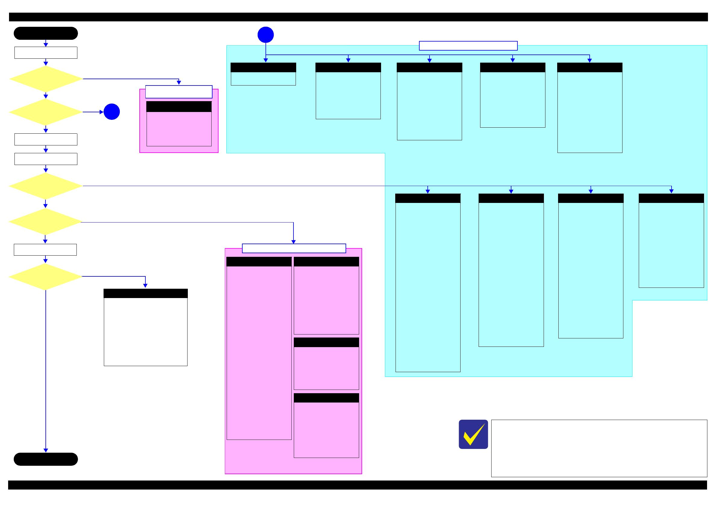
Troubleshooting Troubleshooting Workflow 10
If the reason for the return is evident, first check the phenomenon user
claims recurs, then proceed to the troubleshooting.
This flowchart is compiled based on the following contents.
Our experience regarding the quality problem.
ESK’s repair data.
Printer Mechanism specification for the product.
Fatal error
Please refer to
" 1.3 Fatal Error Code
List (p13)".
Maintenance error
[Occurrence Condition]
This error occurs when
maintenance counter in EEPROM
exceeds the specified value.
[Major Occurrence Timing]
Power-on timing
Print start timing
Cleaning timing
Ink Cartridge replacement
timing
[Troubleshooting]
Porous Pad replacement &
Maintenance counter reset
Ink End error
[Occurrence Condition]
This error occurs when ink
counter reaches ink end level.
[Major Occurrence Timing]
Power-on timing
Print start timing
Cleaning timing
[Troubleshooting]
Refill ink and reset ink counter
by panel.
Incomplete Initial Ink Charge
[Occurrence Condition]
Ink LED is ON and STM
indicates "Initial ink charging is
not complete".
[Major Occurrence Timing]
Print start timing.
[Troubleshooting]
Perform initial ink charge
Paper Jam Fatal error
[Occurrence Condition]
This error occurs when CR Unit is
blocked by jammed paper.
[Major Occurrence Timing]
Power-on timing
[Major Troubleshooting]
Remove jammed paper
[NOTE]
On this product, if CR Unit
touches jammed paper, CR Unit
moves back in the opposite
direction so that customer can
remove the paper. However, if CR
Unit cannot move in this
sequence, this error occurs.
Paper Jam error
[Occurrence Condition]
This error occurs when top/
bottom of paper is not detected by
PE Sensor in the specified steps of
paper loading / ejecting operation
correctly.
[Major Occurrence Timing]
Power-on timing
Paper loading timing
Paper eject timing
[Major Troubleshooting]
1 Perform paper eject operation
from operation panel.
•Success
Starts paper feeding
operation again if printer has
print data.
•Fail
Occurs paper jam error
again.
2 If fail in the above 1, remove
the paper by opening Scanner
Unit.
3 Perform paper eject operation
from operation panel again.
•Success
Starts paper feeding
operation again if printer has
print data.
•Fail
Occurs paper jam error
again.
4 If fail in the above 3, check
foreign material / part come-
off / PE Sensor Lever / PE
Sensor / Porous Pad on Paper
Guide Front / Main board.
No Paper error
[Occurrence Condition]
This error occurs when top of
paper can not be detected
correctly by PE Sensor in the
specified steps up to completion
of the paper loading operation.
(No paper / No loading / large
paper skew)
[Major Occurrence Timing]
Paper loading timing
[Major Troubleshooting]
1 Set paper in ASF and perform
paper feed operation.
2 If the paper stops before
reaching PE Sensor, remove it
and check the paper condition.
3 A) If paper is OK, set paper in
ASF and move edge guides to
appropriate position, and
perform 2 again.
B) If damage in the above 2,
check foreign materials /
parts come-off / parts
transformation in paper
path.
4 If not resolved by 3-A & 3-B,
check foreign material / Part
come-off / surface condition of
LD Roller or PF Roller / PE
Sensor Lever / PE Sensor /
Main Board / PF Motor.
Double Feed error
[Occurrence Condition]
When manual duplex printing is
selected using the printer driver,
this error occurs if the actual
paper length detected by PE
Sensor does not match with the
paper length specified in the
printer driver. (The error occurs
when the actual length is longer
than the theoretical length
specified in the driver.)
[Major Occurrence Timing]
Paper loading timing
Paper eject timing
[Troubleshooting]
PE Sensor Lever replacement
PE Sensor replacement
(Main Board replacement)
Main Board replacement
[NOTE]
This error may occur in the
manual duplex printing if the
inverted sheet printed on the first
side sticks to the second sheet
when the first side printing is
complete and the sheet is inverted
and set to ASF to print on the
other side.
Paper Size Unmatch error
[Occurrence Condition]
This error occurs if the actual
paper length detected by PE
Sensor does not match with the
paper length specified in the
printer driver. (The error occurs
no matter when the actual length
is longer or shorter than the
theoretical length specified in the
driver.)
[Major Occurrence Timing]
Paper eject timing
[Troubleshooting]
PE Sensor Lever replacement
PE Sensor replacement
(Main Board replacement)
Main Board replacement
No Power
*2
[Presumable Cause]
•PS Unit damage
Main Board damage
[Major Troubleshooting]
PS Unit replacement
Main Board replacement
Poor Printing
[Phenomenon]
Poor printing quality
Ink stain on paper
Dot missing
Paper eject without printing
[Presumable Cause]
Driver / Panel mis-setting
Contamination of CR scale
Contamination of Printhead
cover
Printhead damage
Ink clogging of Printhead
Contamination on Cap Unit /
Wiper of Ink System Assy
Ink System Assy damage
Float of Porous Pad on Paper
Guide Front
Narrower/Wider PG
(out of standard)
PE Sensor Lever damage
PE Sensor damage
Ink tank ventilation film gets
wet.
[Major Troubleshooting]
Driver / Panel re-setting
CR Scale replacement
Printhead cover cleaning
Printhead cleaning
Ink Cartridge replacement
Printhead replacement
Rubber cleaning of Cap Unit
Ink System Assy replacement
Porous Pad re-installation
Printer replacement
PE Sensor Lever replacement
PE Sensor replacement
(Main Board replacement)
Ink tank replacement
Poor Paper Loading
[Presumable Cause]
Use of 3rd party media
Edge guide mis-setting
Foreign material
Part come-off
Contamination of LD Roller or
PF roller
[Major Troubleshooting]
Recommendation of EPSON
media
Edge guide re-setting
Foreign material removal
Part re-installation
Roller replacement
Abnormal Noise
[Presumable Cause]
Foreign material
Insufficient grease
•Gear damage
[Major Troubleshooting]
Foreign material removal
Lubrication of grease
Gear replacement
Scanner failure
[Presumable Cause]
Contamination of Scanner Glass
Contamination of Document Pad
CIS Unit bonding failure
CIS Unit damage
Scanner Motor damage
Insufficient grease
[Major Troubleshooting]
Scanner Glass cleaning
Document Pad cleaning
Document Pad replacement
CIS Unit replacement
Scanner Motor replacement
Lubrication of grease
Finish
*3
Turn on the power
*1
1
1
Major problem without error message
Print check pattern
Is printing operation
finished without trouble?
Start
No
Yes
Yes
No
Yes
No
Yes
*1: If the Hopper of ASF on the returned product touches the LD Roller, the initial ink charge has
not been completed for the product yet.
*2: If the printer can turn on but turns off right away, the protection circuit may cut off the power
due to an error such as a circuit failure.
*3: In case of “Not Trouble Found”, check fatal error code.
Major problem with error message
Major problem without
error message
Is Power-on sequence
finished without error?
No
Is scanning operation
finished without trouble?
Standby condition
Does printer turn on the
power?
Copy an image
Does an error occur
when printing?
No
Yes
Blank printing
[Phenomenon]
Blank printing
[Presumable Cause]
Ink tank ventilation film gets
wet
Ink rumples
Ink onnection is incomplete.
[Major Troubleshooting]
Ink tank replacement
Ink tube re-installation
Confidential
Troubleshooting Power-On Sequence 11
L365/L366,L360/L362,L310/L312,L220/L222,L130/L132 Series
Revision A
1.2 Power-On Sequence
This section describes the power-on sequences in two conditions. The preconditions are as follows.
Condition 1: Normal power-on sequence (See Table 1-1.)
Turning on the printer after turning it off without an error.
Initial ink charge has finished and every cartridge has sufficient ink.
No paper on the paper path.
The Printhead is capped with the Cap Assy.
The CR Unit is normally fixed by the Change Lever.
Maintenance error recovery has never been performed.
Note 1: The rotation directions of the PF Motor are as follows.
Clockwise: Paper is fed normally
Counterclockwise: Paper is fed backward
*2: The conditions of the CR lock are as follows.
Red CR lock is set
White CR lock is released
*3: The fatal error occurs if there is a problem such as the fuse blew.
*4: The empty suction operation may occur depending on the situation.
*5: Executed when the detected temperature is under 5
o
C (41
o
F) by the thermistor on the Printhead.
Table 1-1. Condition 1: Normal Power-on Sequence
Operation
*1
CR Unit/PF Roller
movement and
position
*2
1. Printhead initialization and fuse inspection
1-1.Initializes the Printhead, and checks for the fuse on the circuit boards in the printer.
*3
2. Checking for waste ink overflow
2-1.Checks the waste ink counter if the waste ink overflow is occurring.
3. Seeking the home position
3-1.The CR Unit moves to the 80-digit side slowly and confirms it touches the Change Lever (CR lock).
3-2.The CR Unit moves to the 0-digit side slowly.
3-3.After the PE Sensor checks if paper exists, the PF Motor rotates clockwise for one second and releases the CR lock.
3-4.While checking if the CR Unit does not touch the Change Lever (CR lock) or the foreign material, the CR Unit
moves to the 80-digit side slowly until it touches the Left Frame.
3-5.The distance from the position where the CR Unit touched to the Left Frame is regarded as the standard distance
from the origin position, and the home position is fixed.
From then on, the CR Unit position is monitored according to the signals from the CR Encoder.
3-6.The CR Unit moves to near its home position quickly.
4. PF Motor Measurement
4-1.The PF Motor rotates clockwise until the PF Roller turns five times to perform a load measurement.
5. Detecting ink cartridge and initializing ink system
*4
5-1.The CR Unit returns to its home position.
6. Low temperature operation sequence
*5
6-1.The CR Unit quickly moves back and forth between near the Change Lever and near the Left Frame for two times.
Confidential
Troubleshooting Power-On Sequence 12
L365/L366,L360/L362,L310/L312,L220/L222,L130/L132 Series
Revision A
Condition 2: Power-on sequence after recovering from a paper jam error (See Table 1-2.)
Turning on the printer after turning it off with a paper jam fatal error.
There still remains paper on the paper path out of the detecting area of the PE Sensor.
Maintenance error recovery has never been performed.
Note *1: “Paper exists” is detected when the CR Unit touches the paper. When “paper does not exist” is detected, the power-on sequence
of condition 1 (
Table 1-1
) is executed from No.4.
*2: If the paper jam error cannot be solved after repeating the power-on sequence on condition 2 (
Table 1-2
) twice, the printer turns
into the paper jam fatal error for the third time.
Table 1-2. Condition 2: Power-on Sequence after Recovering from a Paper Jam Error
Operation
CR Unit/PF Roller
movement and
position
Executes No.1 to No.3 on the normal power-on sequence (Table 1-1).
4. Detecting remaining paper
4-1.5.The CR Unit returns to its home position.
4-2.The CR Unit moves to the 80-digit side and confirms there is no paper.
*1
4-3.The CR Unit quickly returns to its home position, and displays on the LCD or with flashing LEDs that the paper jam
error occurs.
When the user removes the paper and releases the paper jam error by panel operation, the normal power-on sequence from No.1 (Table 1-1) is executed
again.
*2
To recover from the maintenance error, the dedicated software that can be downloaded
from the web site which can be accessed from STM3 is required.
The printer operation related to the maintenance error recovery is as follows.
When the waste ink counter reaches the threshold value (1) for the first time and the
maintenance error occurs, the counter threshold of the maintenance error is changed
to threshold value 2 after performing recovery from the maintenance error.
After the threshold value (2) is enabled, the warning; to notify the possibility of ink
leakage out of the printer, is displayed every time the waste ink counter increases by
1%.
If the waste ink counter reaches the threshold value (2), the maintenance error occurs.
Then, the waste ink counter is changed back to the threshold value (1) after recovering
from the maintenance error, and the warning is displayed repeatedly according to the
increment of the waste ink counter until the maintenance error occurs when the
threshold value (2) is reached.
(Recovery from the maintenance error can be performed up to the specified number
of times.)
Confidential
Troubleshooting Fatal Error Code List 13
L365/L366,L360/L362,L310/L312,L220/L222,L130/L132 Series
Revision A
1.3 Fatal Error Code List
This section describes how to check the fatal error code, description, and the possible causes.
1.3.1 Printer Fatal Error Code
This section describes the fatal error code and the possible cause for this product.
Error type
Error
code
Error name Possible cause
Scanner
0x10 HP detection failure
CIS Unit failure
Scanner Housing failure
Main Board failure
Insufficient grease
Foreign object
FFC for CIS failure / FFC for CIS connection failure
0x14 Measurement error
Scanner drive mechanism was overloaded.
Insufficient grease
Foreign object
Lack of gears
Deformation of the shaft
0x20 LED light failure
CIS Unit failure
Main Board failure
0x51 Auto judge Fatal Error 1
---*
0x52 Auto judge Fatal Error 2
0x53 Auto judge Fatal Error 3
0x54 Auto judge Fatal Error 4
0x55 Auto judge Fatal Error 5
Printer
0x60 Home position
Carriage overload error (paper jam/foreign object)
Deformation of the Main Frame
Ink system failure
CR Motor failure
Deformation of the Front Frame
CR Encoder failure (contaminated/detached scale, Encoder Board
failure)
Cable disconnection
0x63
Ink cartridge replacement timing contact
detection error (Power off)
Paper jam
Foreign object
Deformation of the Main Frame
0x64 Paper-Jam cancelation disable error
Paper jam
Foreign object
0x81 PIS environmental error Diffused light
0x82 PIS continuous reflected light error
PIS failure
Main Board failure
Diffused light
0x83 PIS No reflected light error PIS failure (installation posture, contamination)
0x84 PIS shift length error
Home position gap
Diffused light
0x87 PIS Empty Jig error PIS failure (installation posture, contamination)
0x88 Excessive Light error
PIS failure
Main Board failure
Diffused light
0x89 Insufficient Light error
PIS failure (installation posture, contamination)
Main Board failure
Ink cartridge failure
0x8F EEPROM verify error (by command)
---*
Confidential
Troubleshooting Fatal Error Code List 14
L365/L366,L360/L362,L310/L312,L220/L222,L130/L132 Series
Revision A
Printer
0x9A Circuit error (include blowout of a fuse)
Main Board failure
0x9B Transistor temperature error
0x9C X-Hot detect error (pre printing)
Printhead failure
Main Board failure
0x9D X-Hot detect error (after flushing)
0x9E Head temperature error
0xB9 Other Ink device error
Ink cartridge failure
CSIC Terminal failure
CR Contact Module failure
Main Board failure
Cable disconnection
0xBA Other Ink device error
0xC0 CRCM access error
0xC1 CRCM access error
0xC3 Other Ink device error
0xE1 CR PID excess load error
CR Encoder failure (contaminated/detached scale, Encoder Board
failure)
CR Motor failure
Carriage overload error (paper jam/foreign object)
Cable disconnection
0xE2 CR PID excess speed error
CR Encoder failure (contaminated/detached scale, Encoder Board
failure)
Motor driver failure (Main Board failure)
Slipping teeth of the CR Timing Belt
Improper tension of the CR Timing Belt
0xE3 CR PID reverse error
CR Encoder failure (contaminated/detached scale, Encoder Board
failure)
Slipping teeth of the CR Timing Belt
Improper tension of the CR Timing Belt
Carriage overload error (paper jam/foreign object)
0xE4 CR PID lock error
CR Encoder failure (contaminated/detached scale, Encoder Board
failure)
CR Motor failure
Carriage overload error (paper jam/foreign object)
Cable disconnection
0xE8 CR load position reverse error
CR Encoder failure (contaminated/detached scale, Encoder Board
failure)
Slipping teeth of the CR Timing Belt
Improper tension of the CR Timing Belt
Carriage overload error (paper jam/foreign object)
0xE9 CR load position excess speed error
CR Encoder failure (contaminated/detached scale, Encoder Board
failure)
Motor driver failure (Main Board failure)
Slipping teeth of the CR Timing Belt
Improper tension of the CR Timing Belt
0xEA CR load position excess load error
CR Encoder failure (contaminated/detached scale, Encoder Board
failure)
CR Motor failure
Carriage overload error (paper jam/foreign object)
Cable disconnection
0xEE CR PID driving time error
Main Board failure
0xEF
CR load position excess driving time
error
0xF1 PF PID excess load error
PF Encoder failure (contaminated/detached scale, Encoder Board
failure)
PF Motor failure
PF drive mechanism overload (paper jam/foreign object)
Cable disconnection
Error type
Error
code
Error name Possible cause
Confidential
Troubleshooting Fatal Error Code List 15
L365/L366,L360/L362,L310/L312,L220/L222,L130/L132 Series
Revision A
Note "*": Not occurs except in manufacturing process.
Printer
0xF2 PF PID excess speed error
PF Encoder failure (contaminated/detached scale, Encoder Board
failure)
Motor driver failure (Main Board failure)
Slipping gears have occurred around the PF Motor gears.
0xF3 PF PID reverse error
PF Encoder failure (contaminated/detached scale, Encoder Board
failure)
Slipping gears have occurred around the PF Motor gears.
Paper jam
0xF4 PF PID lock error
PF Encoder failure (contaminated/detached scale, Encoder Board
failure)
PF Motor failure
PF drive mechanism overload (paper jam/foreign object)
Cable disconnection
0xF8 PF load position reverse error
PF Encoder failure (contaminated/detached scale, Encoder Board
failure)
Slipping gears have occurred around the PF Motor gears.
0xF9 PF load position reverse error
PF Encoder failure (contaminated/detached scale, Encoder Board
failure)
Motor driver failure (Main Board failure)
Slipping gears have occurred around the PF Motor gears.
0xFA PF load position excess load error
PF Encoder failure (contaminated/detached scale, Encoder Board
failure)
PF Motor failure
PF drive mechanism overload (paper jam/foreign object)
Cable disconnection
0xFE PF PID driving time error
Main Board failure
0xFF PF load position excess driving time error
Error type
Error
code
Error name Possible cause
Confidential
CHAPTER 2
DISASSEMBLY/REASSEMBLY
Confidential
Disassembly/Reassembly Overview 17
L365/L366,L360/L362,L310/L312,L220/L222,L130/L132 Series
Revision A
2.1 Overview
This chapter describes procedures for disassembling the main parts/units of this product. Unless otherwise
specified, disassembled parts/units can be reassembled by reversing the disassembly procedure. See the cautions
or tips for disassembly/reassembly described in "2.3 Detailed Disassembly/Reassembly Procedure for each Part/
Unit (p41)".
Read the "Safety Precautions(p3)" before disassembling and reassembling.
When you have to remove units or parts that are not described in this chapter, see the exploded diagrams of SPI
(Service Parts Information).
2.1.1 Tools
Use only specified tools to avoid damaging the printer.
Note 1: Some of the tools listed above are commercially available.
2: EPSON provides the tools listed with EPSON part code.
2.1.2 Jigs
Note *: If performing the disassembling/reassembling procedure is difficult using tweezers such as when reassembling " Cap Lever/Cap
Assy (p44)", the spring hook jig helps you to remove/attach the spring easier.
2.1.2.1 Making the Spring Hook Jig
Fold a clip (commercial item) as shown in Fig. 2-1.
Figure 2-1. Making the Spring Hook Jig
In this chapter, the product names are called as follows:
L360/L362 Series:L365/L366
L360/L362 Series:L360,L363/L362
L310/L312 Series:L310,L313/L312
L220/L222 Series:L220/L222
L130/L132 Series:L130/L132
Name Availability EPSON Part Code
(+) Phillips screwdriver #1 O 1080530
(+) Phillips screwdriver #2 O ---
Flathead screwdriver O ---
Flathead Precision screwdriver #1 O ---
Tweezers O ---
Longnose pliers O ---
Acetate tape --- 1003963
Name Quantity EPSON Part Code
Spring hook jig* 1 Can be made with a commercial item See " Making the Spring Hook Jig (p17)".
Thickness gauge (1.5 mm) 2 Commercially available
Thickness gauge (2.0 mm) 2 Commercially available
Sonic tension meter 1 1294120
Before folding
Fold here
Clip
40 mm or more
After folding
Fold appropriate length
to hitch a spring.
Clip
Confidential
Disassembly/Reassembly Overview 18
L365/L366,L360/L362,L310/L312,L220/L222,L130/L132 Series
Revision A
2.1.3 Locations of the Parts/Units
This section shows the locations of the main parts/units of this product.
Exterior parts
Figure 2-2. Exterior Parts
The parts/units which can not be seen in the following pictures are indicated in dotted lines
().
No. Name No. Name
1
Housing Rear (p33) (L365/L366,L360/L362,L220/L222
Series only)
5
Hinge (p37) (L365/L366,L360/L362,L220/L222 Series
only)
2 Tray Front Assy (p33) 6
Housing Right (p37) (L365/L366,L360/L362,L220/L222
Series only)
3
Frame Base Assy (p35)
7
Housing Left (p33) (L365/L366,L360/L362,L220/L222
Series only)
4
Panel Unit
L365/L366 Series (p 35)
Panel Board Assy (p38) / Panel Buttons (p38) /
Panel Housing Upper Assy (p38) / Panel Housing
Lower Assy (p38)
L360/L362,L220/L222 Series (p 35)
Panel Board Assy (p38) / Panel Buttons (p38) /
Panel Housing Upper Assy (p38) / Panel Housing
Lower Assy (p38)
8
Scanner Unit (p33) (L365/L366,L360/L362,L220/L222
Series only)
Scanner Housing Upper (p37) / Scanner Carriage Unit
(p37) / Scanner Housing Lower (p37) / CIS Module
Unit (p37) / Scanner Motor (p37)
9 Paper Support Assy (p33)
1
2 3 4
Front
5
6
Right
9
Rear
8
7
Left
Confidential
Disassembly/Reassembly Overview 19
L365/L366,L360/L362,L310/L312,L220/L222,L130/L132 Series
Revision A
Printer mechanism
Figure 2-3. Printer Mechanism: Front
Figure 2-4. Printer Mechanism: Right
No. Name No. Name
1 CR Driven Pulley Assy (p35) 7 CR Unit (p39)
2 CR Scale (p35) 8 PF Roller Unit (p39)
3 CR Timing Belt (p39) 9 Star Wheel Holder Assy (p37)
4 Printhead (p33) 10 Paper Guide Upper Assy (p39)
5 CR Encoder Sensor (p39) 11 Paper Guide Front Unit (p33)
6 Adapter (p37) 12 Adapter Cover (p37)
No. Name No. Name
1 LD Roller Cover (p35) 6 Cap Lever (p37)
2 LD Roller Assy (p35) 7 Cap Assy (p37)
3 Hopper (p35) 8 Porous Pad for Cap Assy (p37)
4 Retard Roller Assy (p33) 9 Pump Unit (p39)
5 Paper Back Lever (p33)
1
2
3
5
8 11
7
10
4
9
6
12
6 7 8 9
5
4
31 2
Confidential
Disassembly/Reassembly Overview 20
L365/L366,L360/L362,L310/L312,L220/L222,L130/L132 Series
Revision A
Figure 2-5. Printer Mechanism: Left
Figure 2-6. Printer Mechanism: Rear
No. Name No. Name
1 Wireless LAN Module (p33) (L365/L366 Series only) 5 PF Scale (p36)
2 EJ Roller (p37) 6 PF Encoder Sensor (p36)
3 PF Motor Assy (p39) 7 EJ Roller Gear (p33)
4 PF Timing Belt (p36)
No. Name No. Name
1 CR Motor (p35) 4 Waste Ink Pad Assy (p33)
2 Head FFC (p39) 5 PE Sensor Lever (p35)
3 Main Board (p35) 6 PS Unit (p33)
3
1
2
7
4
5 6
1
2
4
5
6
3
  • Page 1 1
  • Page 2 2
  • Page 3 3
  • Page 4 4
  • Page 5 5
  • Page 6 6
  • Page 7 7
  • Page 8 8
  • Page 9 9
  • Page 10 10
  • Page 11 11
  • Page 12 12
  • Page 13 13
  • Page 14 14
  • Page 15 15
  • Page 16 16
  • Page 17 17
  • Page 18 18
  • Page 19 19
  • Page 20 20
  • Page 21 21
  • Page 22 22
  • Page 23 23
  • Page 24 24
  • Page 25 25
  • Page 26 26
  • Page 27 27
  • Page 28 28
  • Page 29 29
  • Page 30 30
  • Page 31 31
  • Page 32 32
  • Page 33 33
  • Page 34 34
  • Page 35 35
  • Page 36 36
  • Page 37 37
  • Page 38 38
  • Page 39 39
  • Page 40 40
  • Page 41 41
  • Page 42 42
  • Page 43 43
  • Page 44 44
  • Page 45 45
  • Page 46 46
  • Page 47 47
  • Page 48 48
  • Page 49 49
  • Page 50 50
  • Page 51 51
  • Page 52 52
  • Page 53 53
  • Page 54 54
  • Page 55 55
  • Page 56 56
  • Page 57 57
  • Page 58 58
  • Page 59 59
  • Page 60 60
  • Page 61 61
  • Page 62 62
  • Page 63 63
  • Page 64 64
  • Page 65 65
  • Page 66 66
  • Page 67 67
  • Page 68 68
  • Page 69 69
  • Page 70 70
  • Page 71 71
  • Page 72 72
  • Page 73 73
  • Page 74 74
  • Page 75 75
  • Page 76 76
  • Page 77 77
  • Page 78 78

Epson L360 User manual

Category
Print & Scan
Type
User manual

Ask a question and I''ll find the answer in the document

Finding information in a document is now easier with AI