Toro Power Clear 721 R Snowthrower User guide

Category
Snow throwers
Type
User guide
CV
FormNo.3439-829RevA
PowerClear
®
721Snowthrower
ModelNo.38752—SerialNo.406765202andUp
ModelNo.38753—SerialNo.406836564andUp
ModelNo.38756—SerialNo.406728558andUp
Operator'sManual
Introduction
Thismachineisintendedtobeusedbyresidential
homeowners.Itisdesignedprimarilyforremoving
snowfrompavedsurfaces,suchasdrivewaysand
sidewalks,andothersurfacesfortrafconresidential
orcommercialproperties.Itisnotdesignedfor
removingmaterialsotherthansnow,norisitdesigned
forclearinggravelsurfaces.Usingthisproductfor
purposesotherthanitsintendedusecouldprove
dangeroustoyouandbystanders.
Readthisinformationcarefullytolearnhowtooperate
andmaintainyourproductproperlyandtoavoid
injuryandproductdamage.Youareresponsiblefor
operatingtheproductproperlyandsafely.
Visitwww.Toro.comforproductsafetyandoperation
trainingmaterials,accessoryinformation,helpnding
adealer,ortoregisteryourproduct.
Wheneveryouneedservice,genuineT oroparts,or
additionalinformation,contactanAuthorizedService
DealerorToroCustomerServiceandhavethemodel
andserialnumbersofyourproductready.Figure1
identiesthelocationofthemodelandserialnumbers
ontheproduct.Writethenumbersinthespace
provided.
Important:Withyourmobiledevice,youcan
scantheQRcodeontheserialnumberdecal(if
equipped)toaccesswarranty,parts,andother
productinformation.
g291503
Figure1
1.Modelandserialnumberlocation
ModelNo.
SerialNo.
Thismanualidentiespotentialhazardsandhas
safetymessagesidentiedbythesafety-alertsymbol
(Figure2),whichsignalsahazardthatmaycause
seriousinjuryordeathifyoudonotfollowthe
recommendedprecautions.
g000502
Figure2
Safety-alertsymbol
Thismanualuses2wordstohighlightinformation.
Importantcallsattentiontospecialmechanical
informationandNoteemphasizesgeneralinformation
worthyofspecialattention.
Important:Ifyouareusingthismachineabove
1500m(5,000ft)foracontinuousperiod,ensure
thattheHighAltitudeKithasbeeninstalled
sothattheenginemeetsCARB/EPAemission
regulations.TheHighAltitudeKitincreases
engineperformancewhilepreventingspark-plug
fouling,hardstarting,andincreasedemissions.
Onceyouhaveinstalledthekit,attachthe
©2020—TheToro®Company
8111LyndaleAvenueSouth
Bloomington,MN55420
Registeratwww.Toro.com.
OriginalInstructions(EN)
PrintedinMexico
AllRightsReserved
*3439-829*A
high-altitudelabelnexttotheserialdecalonthe
machine.ContactanyAuthorizedToroService
DealertoobtaintheproperHighAltitudeKitand
high-altitudelabelforyourmachine.Tolocate
adealerconvenienttoyou,accessourwebsite
atwww.Toro.comorcontactourToroCustomer
CareDepartmentatthenumber(s)listedinyour
EmissionControlWarrantyStatement.Remove
thekitfromtheengineandrestoretheengineto
itsoriginalfactorycongurationwhenrunningthe
engineunder1500m(5,000ft).Donotoperatean
enginethathasbeenconvertedforhigh-altitude
useatloweraltitudes;otherwise,youcould
overheatanddamagetheengine.
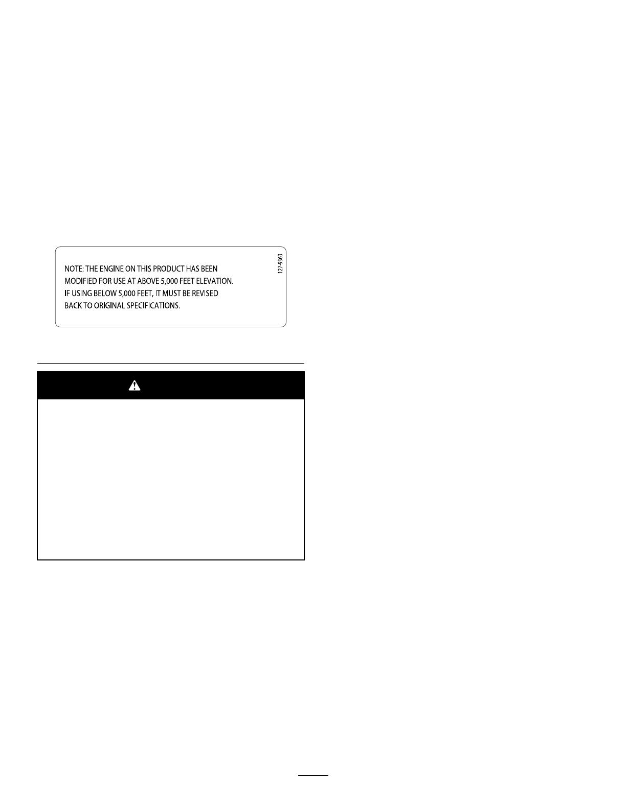
Ifyouareunsurewhetherornotyourmachinehas
beenconvertedforhigh-altitudeuse,lookforthe
followinglabel(Figure3).
decal127-9363
Figure3
WARNING
CALIFORNIA
Proposition65Warning
Theengineexhaustfromthisproduct
containschemicalsknowntotheStateof
Californiatocausecancer,birthdefects,
orotherreproductiveharm.
Useofthisproductmaycauseexposure
tochemicalsknowntotheStateof
Californiatocausecancer,birthdefects,
orotherreproductiveharm.
Contents
Introduction...............................................................1
Safety.......................................................................3
GeneralSafety...................................................3
SafetyandInstructionalDecals..........................4
Setup........................................................................5
1UnfoldingtheHandle.......................................5
2InstallingtheRecoil-StartGuideand
Rope...............................................................5
3InstallingtheDischargeChute.........................5
4FillingtheEnginewithOil.................................6
5AdjustingtheControlCable..............................7
ProductOverview.....................................................8
Specications....................................................8
Attachments/Accessories...................................8
Operation..................................................................9
BeforeOperation...................................................9
BeforeOperationSafety.....................................9
FillingtheFuelT ank............................................9
CheckingtheEngine-OilLevel..........................10
DuringOperation..................................................11
DuringOperationSafety....................................11
StartingtheEngine............................................11
EngagingtheRotorBlades...............................13
DisengagingtheRotorBlades..........................13
ShuttingOfftheEngine.....................................13
AdjustingtheDischargeChuteandChute
Deector.......................................................13
AdjustingtheDischargeChuteandChute
Deector.......................................................13
ClearingaCloggedDischargeChute................14
OperatingTips.................................................14
AfterOperation....................................................14
AfterOperationSafety......................................14
PreventingFreeze-upafterUse........................14
Maintenance...........................................................16
RecommendedMaintenanceSchedule(s)...........16
MaintenanceSafety..........................................16
CheckingandAdjustingtheControl
Cable............................................................16
InspectingtheRotorBlades..............................17
ChangingtheEngineOil...................................18
ReplacingtheSparkPlug.................................19
ReplacingtheDriveBelt...................................19
AdjustingtheQuickShootControl....................20
Storage...................................................................22
StorageSafety..................................................22
StoringtheMachine..........................................22
2
Safety
Thismachinehasbeendesignedinaccordancewith
ANSI/OPEIB71.3specications.
GeneralSafety
Thisproductiscapableofamputatinghandsand
feetandofthrowingobjects.Alwaysfollowallsafety
instructionstoavoidseriouspersonalinjury.
Readandunderstandthecontentsofthis
OperatorsManualbeforeyoustarttheengine.
Ensurethateveryoneusingthisproductknows
howtouseit,knowshowtoshutofftheengine
quickly,andunderstandsthewarnings.
Shutofftheenginewheneveryouleavethe
operatingpositionforanyreason.
Donotputyourhandsorfeetnearmovingparts
onthemachine.
Donotoperatethemachinewithoutallguards
andothersafetyprotectivedevicesinplaceand
working.
Keepclearofanydischargeopening.Keep
bystanders,especiallysmallchildren,outofthe
operatingarea.
Neverallowchildrentooperatethemachine.
3
SafetyandInstructionalDecals
Safetydecalsandinstructionsareeasilyvisibletotheoperatorandarelocatednearanyarea
ofpotentialdanger.Replaceanydecalthatisdamagedormissing.
decal94-2577
94-2577
1.Toengagetherotorblades,holdthecontrolbaragainst
thehandle.
2.Todisengagetherotorblades,releasethecontrolbar.
OrderPartNo.117-9121
decal115-5698
115-5698
1.Cutting/dismembermenthazard,impellerandauger—do
notplaceyourhandinthechute;removethekeyandread
theOperator’sManualbeforeperformingmaintenance.
decal133-8061
133-8061
decal139-3505
139-3505
1.Insertthekey,pressthe
primer3times,movethe
chokelevertotheleft,pull
therecoil-starthandle,and
oncetheengineisrunning
movethechokeleverto
theright.
4.Thrownobject
hazard—keepbystanders
away.
2.Warning—readthe
Operator’sManual.
5.ReadtheOperator’s
Manualbeforeservicing
theengineoillevel.
3.Explosionhazard—donot
tipthemachine.
6.Cutting/dismemberment
hazardofthehand,
rotor—shutofftheengine,
removethekey,andwait
forallmovingpartsto
stopbeforeleavingthe
machine.
decal139-3506
139-3506
1.ReadtheOperator’sManual—plugthemachineintopower
theelectricstarter,presstheelectric-startbuttontostartthe
engine,andthenremovetheplugfromthemachine.
4
Setup
1
UnfoldingtheHandle
NoPartsRequired
Procedure
g287663
2
InstallingtheRecoil-StartGuideandRope
NoPartsRequired
Procedure
g286483
5
3
InstallingtheDischargeChute
NoPartsRequired
Procedure
Models38752and38753
g291515
Model38756
g262492
6
4
FillingtheEnginewithOil
NoPartsRequired
Procedure
g324210
5
AdjustingtheControlCable
NoPartsRequired
Procedure
RefertoCheckingandAdjustingtheControlCable
(page16).
7
ProductOverview
g291536
Figure9
Models38752and38753
1.Chutedeector5.Controlbar
2.Chute-deectortrigger6.Oil-drainplug
3.Chutehandle7.Oilll/dipstick
4.Fuel-tankcap
g280271
Figure10
Model38756
1.Chutedeector5.QuickShoot™control
2.Chute-deectortrigger6.Oil-drainplug
3.Fuel-tankcap
7.Oilll/dipstick
4.Controlbar
g280282
Figure11
1.Recoil-starthandle5.Key
2.Electric-startplug-in
(electric-startmodelsonly)
6.Primer
3.Electric-startbutton
(electric-startmodels
only)
7.Fuel-tankcap
4.Choke
Specications
ModelWeightLengthWidthHeight
38kg
38752
(84lb)
38kg122cm54cm107cm
38753
(84lb)
39kg
38756
(86lb)
(48
inches)
(21
inches)
(42
inches)
Attachments/Accessories
AselectionofT oroapprovedattachmentsand
accessoriesisavailableforusewiththemachine
toenhanceandexpanditscapabilities.Contact
yourAuthorizedServiceDealerorauthorizedT oro
distributororgotowww.Toro.comforalistofall
approvedattachmentsandaccessories.
Toensureoptimumperformanceandcontinuedsafety
certicationofthemachine,useonlygenuineToro
replacementpartsandaccessories.Replacement
partsandaccessoriesmadebyothermanufacturers
couldbedangerous,andsuchusecouldvoidthe
productwarranty.
8
Operation
Note:Determinetheleftandrightsidesofthe
machinefromthenormaloperatingposition.
BeforeOperation
BeforeOperationSafety
GeneralSafety
Forelectric-startmodelsonly:Useextension
cordsandreceptaclesasspeciedinthemanual.
Inspecttheelectricalcordbeforepluggingitinto
apowersource.Ifthecordisdamaged,replace
it.Unplugthepowercordwheneveryouarenot
startingthemachine.
Wearappropriateclothing,includingeye
protection;longpants;substantial,slip-resistant
footwear;andhearingprotection.Tiebacklong
hair,securelooseclothing,anddonotwearloose
jewelry.
Thoroughlyinspecttheareawhereyouwillusethe
machine,andremovealldoormats,sleds,boards,
wires,andotherforeignobjects.
Ifashield,safetydevice,ordecalisdamaged,
illegible,ormissing,repairorreplaceitbefore
beginningoperation.Also,tightenanyloose
fasteners.
FuelSafety
Fuelisextremelyammableandexplosive.Areor
explosionfromfuelcanburnyouandothers.
Topreventastaticchargefromignitingthefuel,
placethecontainerand/ormachineontheground
beforelling,notinavehicleoronanobject.
Fillthefueltankoutdoorswhentheengineiscold.
Replacethefuelcapsecurelyandwipeupspills.
Donothandlefuelwhensmokingoraroundan
openameorsparks.
Storefuelinanapprovedfuelcontainer,outofthe
reachofchildren.
Whenfuelisinthetank,tipthemachineonlyas
directedintheinstructions.
Ifyouspillfuelonyourclothing,changeyour
clothingimmediately.
FillingtheFuelTank
TypeUnleadedgasoline
Minimumoctanerating
87(US)or91(research
octane;outsidetheUS)
Ethanol
Nomorethan10%byvolume
MethanolNone
MTBE(methyltertiarybutyl
ether)
Lessthan15%byvolume
OilDonotaddtothefuel
Useonlyclean,fresh(nomorethan30daysold),fuel
fromareputablesource.
FillthefueltankasshowninFigure12;donotll
abovethebottomofthefueltankneck.
g216203
Figure12
Important:Forbestresults,purchaseonlythe
quantityoffuelthatyouexpecttousein30days.
Otherwise,addfuelstabilizer/conditionertofresh
fuelasdirectedbythefuel-stabilizer/conditioner
manufacturer.
9
CheckingtheEngine-OilLevel
ServiceInterval:Beforeeachuseordaily—Checktheengine-oillevelandaddoilifnecessary.
g293393
Figure13
10
DuringOperation
DuringOperationSafety
GeneralSafety
Shutofftheenginebeforeuncloggingthe
machineandalwaysuseastickorthe
snow-cleanouttool(ifprovided).
Staybehindthehandlesandawayfromthe
dischargeopeningwhileoperatingthemachine.
Keepyourface,hands,feet,andanyotherpart
ofyourbodyorclothingawayfrommovingor
rotatingparts.
Neverdirectthedischargetowardpeopleorareas
wherepropertydamagecanoccur.
Useyourfullattentionwhileoperatingthe
machine.Donotengageinanyactivitythat
causesdistractions;otherwise,injuryorproperty
damagemayoccur.
Exercisecautiontoavoidslippingorfalling,
especiallywhenoperatingthemachineinreverse.
Alwaysbesureofyourfooting,andkeeparm
holdonthehandles.Walk;neverrun.
Exerciseextremecautionwhenoperatingthe
machineonaslope.
Donotoperatethemachinewithoutgoodvisibility
orlight.
Lookbehindandusecarewhenbackingupthe
machine.
Whennotactivelyclearingsnow,disengagepower
totheauger.
Exerciseextremecautionwhenoperatingthe
machineonwalksorroads.Stayalertforhidden
hazardsortrafc.
Neverattempttomakeanyadjustmentswhile
theengineisrunning,exceptasdirectedinthe
instructions.
Afterstrikingaforeignobject,shutofftheengine,
removethekey,andinspectthemachinefor
damage.Repairanydamagebeforestartingthe
machine.
Ifthemachinestartstovibrateabnormally,shutoff
theengineandcheckimmediatelyforthecause.
Donotruntheengineindoors;exhaustfumesare
dangerous.
Donotoverloadthemachinecapacityby
attemptingtoclearsnowattoofastarate.
Shutofftheenginewheneveryouleavethe
operatingposition,beforeclearingorunclogging
thecollector,rotor,ordischargechute,andwhen
makinganyrepairs,adjustments,orinspections.
StartingtheEngine
UsingElectricStart
Electric-startmodelsonly
Note:Removeyourglovewhenyoupushintheprimersothataircannotescapefromtheprimerhole.
Important:Donotusetheprimerorthechokeiftheenginehasbeenrunningandishot.Excessive
primingmayoodtheengineandpreventitfromstarting.
Tousetheelectricstarter(electric-startmodelsonly),connectapowercordtotheelectric-startplug-inrst
andthentoagroundfaultcircuitinterrupter(GFCI)poweroutlet.UseonlyaUL-listed,16-gaugepowercord
recommendedforoutdoorusethatisnotlongerthan15m(50ft).
WARNING
Theelectricalcordcanbecomedamaged,causingashockorre.
Thoroughlyinspecttheelectricalcordbeforepluggingitintoapowersource.Ifthecord
isdamaged,donotuseit.Replaceorrepairthedamagedcordimmediately.Contactan
AuthorizedServiceDealerforassistance.
Important:Runtheelectricstarternomorethan10timesatintervalsof5secondson,then5seconds
off.Runningtheelectricstarterextensivelycanoverheatanddamageit.Iftheenginedoesnotstart
afterthisseriesofattempts,waitatleast40minutestoallowthestartertocoolbeforeattemptingto
startitagain.Iftheenginedoesnotstartafterthesecondseriesofattempts,takethemachinetoan
AuthorizedServiceDealerforservice.
11
CAUTION
Ifyouleavethemachinepluggedintoapowersource,someonecaninadvertentlystartthe
machineandinjurepeopleordamageproperty(electric-startmodelsonly).
Unplugthepowercordwheneveryouarenotstartingthemachine.
g327424
Figure14
UsingRecoilStart
Note:Removeyourglovewhenyoupushintheprimersothataircannotescapefromtheprimerhole.
Important:Donotusetheprimerorthechokeiftheenginehasbeenrunningandishot.Excessive
primingmayoodtheengineandpreventitfromstarting.
g280295
Figure15
12
EngagingtheRotorBlades
Toengagetherotorblades,holdthecontrolbar
againstthehandle(Figure16).
g216251
Figure16
DisengagingtheRotor
Blades
Todisengagetherotorblades,releasethecontrolbar
(Figure17).
g006457
Figure17
ShuttingOfftheEngine
Toshutofftheengine,removethekeyfromthe
ignition.
AdjustingtheDischarge
ChuteandChuteDeector
Models38752and38753
Toraiseorlowertheangleofthechutedeector,
pressthetriggeronthechutedeectorandmovethe
chutedeectorupordown.
Toadjustthedischargechute,movethechutehandle.
g278630
Figure18
1.Chutehandle
2.Trigger
AdjustingtheDischarge
ChuteandChuteDeector
Model38756
Toadjustthedischargechute,pressthetriggerofthe
QuickShoot™controlontherightsideofthehandle
andmoveitupordownalongthehandle.Movingthe
controldownthehandlerotatesthedischargechute
totheleft;movingthecontrolupthehandlerotates
thedischargechutetotheright(Figure19).
13
g280416
Figure19
Toraiseorlowertheangleofthechutedeector,
pressthetriggeronthechutedeectorandmovethe
chutedeectorupordown(Figure20).
g006398
Figure20
1.Chute-deectortrigger2.Chutedeector
ClearingaClogged
DischargeChute
Toclearthechute:
Shuttheengineoff!
Wait10secondstoensurethattherotorblades
havestoppedrotating.
Alwaysuseaclean-outtool;neveruseyourhands.
OperatingTips
WARNING
Therotorbladescanthrowstones,toys,
andotherforeignobjectsandcauseserious
personalinjurytoyouorbystanders.
Keeptheareatobeclearedfreeofall
objectsthattherotorbladescouldpickup
andthrow.
Keepallchildrenandpetsawayfromthe
areaofoperation.
Removethesnowassoonaspossibleafteritfalls.
Overlapeachswathtoensurecompletesnow
removal.
Dischargethesnowdownwindwheneverpossible.
Ifthemachinedoesnotpropelitselfforwardon
slipperysurfacesorinheavysnow,pushforward
onthehandle,butallowthemachinetoworkat
itsownpace.
Themachinemayleaverubbermarksonnew
brushedorlight-coloredconcrete.T estonan
inconspicuouslocationbeforeuse.Thesemarks
arenotpermanent.
AfterOperation
AfterOperationSafety
GeneralSafety
Neverstorethemachinewithfuelinthefuel
tankinsideabuildingwhereignitionsourcesare
present,suchashotwaterheaters,spaceheaters,
orclothesdryers.Allowtheenginetocoolbefore
storingthemachineinanyenclosure.
Whenstoringthemachineformorethan30
days,refertoStorage(page22)forimportant
information.
Runthemachineafewminutesafterthrowing
snowtopreventfreeze-upofthecollectorand
rotor.
PreventingFreeze-upafter
Use
Lettheenginerunforafewminutestoprevent
movingpartsfromfreezing.Shutofftheengine,
waitforallmovingpartstostop,andremoveice
andsnowfromthemachine.
Cleanoffanysnowandicefromthebaseofthe
chute.
14
Rotatethedischargechuteleftandrighttofree
itfromanyicebuildup.
Withthekeyremoved,pulltherecoil-starthandle
severaltimesorconnecttheelectricalcordto
apowersourceandthemachineandpushthe
electric-startbuttononcetopreventtherecoil
starterand/ortheelectricstarterfromfreezingup
(electric-startmodelsonly).
Insnowyandcoldconditions,somecontrolsand
movingpartsmayfreeze.Donotuseexcessive
forcewhentryingtooperatefrozencontrols.Ifyou
havedifcultyoperatinganycontrolorpart,start
theengineandletitrunforafewminutes.
15
Maintenance
RecommendedMaintenanceSchedule(s)
MaintenanceService
Interval
MaintenanceProcedure
Afterthersthour
Checkthecontrolcableandadjustitifnecessary.
Aftertherst2hours
Changetheengineoil.
Beforeeachuseordaily
Checktheengine-oillevelandaddoilifnecessary.
Every100hours
Replacethesparkplug.
Yearly
Checkthecontrolcableandadjustitifnecessary.
InspecttherotorbladesandhaveanAuthorizedServiceDealerreplacetherotor
bladesandscraperifnecessary.
Changetheengineoil.
MaintenanceSafety
Readthefollowingsafetyprecautionsbefore
performinganymaintenanceonthemachine:
Shutofftheengine,removethekey,andwait
forallmovementtostopbeforeyouleavethe
operatorsposition.Allowthemachinetocool
beforeadjusting,servicing,cleaning,orstoringit.
Alwaysweareyeprotectionwhileperformingan
adjustmentorrepairtoprotectyoureyesfrom
foreignobjectsthatthemachinemaythrow.
Checkallfastenersatfrequentintervalsforproper
tightnesstoensurethatthemachineisinsafe
workingcondition.
Donotchangethegovernorsettingsontheengine.
PurchaseonlygenuineT ororeplacementparts
andaccessories.
CheckingandAdjustingthe
ControlCable
CheckingtheControlCable
ServiceInterval:Afterthersthour—Checkthe
controlcableandadjustitif
necessary.
Yearly—Checkthecontrolcableandadjustit
ifnecessary.
Movethecontrolbarbacktowardthehandleto
removetheslackinthecontrolcable(Figure21).
g006401
Figure21
1.Controlbar2.2mmto3mm(1/16inch
to1/8inch)gap
Note:Ensurethata2to3mm(1/16to1/8inch)
gapexistsbetweenthecontrolbarandthehandle
(Figure21).
Important:Thecontrolcablemustcontainsome
slackwhenyoudisengagethecontrolbarforthe
rotorbladestostopproperly.
16
AdjustingtheControlCable
1.Slideupthespringcoverandunhookthespring
fromtheadjusterlink(Figure22).
g006402
Figure22
1.Adjusterlink
3.Springcover
2.Z-tting
4.Unhookthespringhere.
Note:Youcanpulluptheadjusterlinkand
cabletomakeunhookingthespringeasier.
2.MovetheZ-ttingtoahigherorlowerholeon
theadjusterlinkasneededtoobtainthe2to3
mm(1/16to1/8inch)gapbetweenthecontrol
barandthehandle(Figure21).
Note:MovingtheZ-ttinghigherdecreasesthe
gapbetweenthecontrolbarandthehandle;
movingitlowerincreasesthegap.
3.Hookthespringtotheadjusterlinkandslidethe
springcoverovertheadjusterlink.
4.Checktheadjustment;refertoCheckingthe
ControlCable(page16).
Note:Afterextendeduse,thedrivebeltmay
wearandloseitsproperbelttension.Ifthedrive
beltslips(continuouslysqueals)underaheavy
load,disconnectthespringfromtheadjustorlink
andmovetheupperendofthespringtothehole
thatisfurtherfromthepivotpointinthecontrol
bar(Figure23).Thenconnectthespringtothe
adjustorlinkandadjustthecontrolcable.
g006587
Figure23
1.Removetheupperendof
springfromthishole.
3.Pivotpoint
2.Inserttheupperendof
springintothishole.
4.Upperendofspring
Note:Thebeltmayslip(squeal)inwet
conditions;todryoutthedrivesystem,startthe
rotorandrunitwithoutaloadfor30seconds.
InspectingtheRotorBlades
ServiceInterval:Yearly—Inspecttherotorblades
andhaveanAuthorizedService
Dealerreplacetherotorbladesand
scraperifnecessary.
Beforeeachsession,inspecttherotorbladesfor
wear.Whenarotor-bladeedgehasworndownto
thewear-indicatorhole,haveanAuthorizedService
Dealerreplacetherotorbladesandthescraper
(Figure24).
g011544
Figure24
1.Thewear-indicatorholeis
intact;youdonotneedto
replacetherotorblades.
2.Thewear-indicatorholeis
exposed;replacetherotor
bladesandscraper.
17
ChangingtheEngineOil
ServiceInterval:Aftertherst2hours
Yearly
Ifpossible,runtheengineforafewminutesbefore
changingtheoiltowarmit.Warmoilowsbetterand
carriesmorecontaminants.
EngineOilSpecications
Engineoilcapacity
0.6L(20oz)*
OilviscosityRefertoFigure27.
APIserviceclassicationSJorhigher
*Thereisresidualoilinthecrankcaseafteryoudrain
theoil.Donotpourtheentirecapacityofoilintothe
crankcase.Fillthecrankcasewithoilasdirectedin
thefollowingsteps.
1.Siphonthefuelfromthefueltankintoan
approvedfuelcontainer,orruntheengineuntil
itshutsoff.
2.Movethemachinetoalevelsurface.
3.Placeanoil-drainpanundertheoil-drainplug,
removetheplug,andtipthemachinebackward
anddraintheusedoilinthepan(Figure25).
g286519
Figure25
1.Oil-drainplug
4.Afterdrainingtheusedoil,returnthemachineto
theoperatingposition.
5.Installtheoil-drainplugandtightenitsecurely.
6.Cleanaroundtheoilll/dipstick.
7.Unscrewthedipstickandremoveit(Figure26).
g006316
Figure26
1.Dipstick
8.Carefullypourabout3/4oftheenginecapacity
ofoilintotheoil-lltube.
Note:Youmaytipthemachineforward(handle
up)tomakeaddingoileasier.Rememberto
returnthemachinetotheoperatingposition
beforecheckingtheoillevel.
Important:Donottipthemachineallthe
wayforwardontoitsnose,orfuelmayleak
outofthemachine.
UseFigure27belowtoselectthebestoil
viscosityfortheoutdoortemperaturerange
expected.
g011606
Figure27
18
g006374
Figure28
9.Wait3minutesfortheoiltosettleintheengine.
10.Wipethedipstickcleanwithacleancloth.
11.Withthemachineintheoperatingposition,
insertthedipstickintotheoil-lltube,butdonot
screwitin,thenremovethedipstick.
12.Readtheoillevelonthedipstick.
Iftheoillevelonthedipstickistoolow,
carefullypourasmallamountofoilinto
theoil-lltube,wait3minutes,andrepeat
steps10through12untiltheoillevelonthe
dipstickiscorrect.
Iftheoillevelonthedipstickistoohigh,
draintheexcessoiluntiltheoillevelonthe
dipstickiscorrect.
Important:Iftheoillevelintheengineistoo
lowortoohighandyouruntheengine,you
maydamagetheengine.
13.Installthedipstickintotheoil-lltubesecurely.
14.Recycletheusedoilproperly.
ReplacingtheSparkPlug
ServiceInterval:Every100hours—Replacethe
sparkplug.
WARNING
Replacingthesparkplugwhiletheengineis
hotcanresultinburns.
Waituntiltheengineiscooltoreplacethe
sparkplug.
UseaTorosparkplugorequivalent(Champion®
RN9YCorNGKBPR6ES).
1.Removetheboot(Figure29).
g030123
Figure29
1.Spark-plugboot
2.Cleanaroundthebaseofthesparkplug.
3.Removeanddiscardtheoldsparkplug.
Note:Youwillneedaratchetwrenchextension
toremovethesparkplug.
4.Setthegapbetweentheelectrodesonanew
sparkplugat0.76mm(0.030inch)asshown
inFigure30.
g001029
Figure30
1.0.76mm(0.030inch)
ReplacingtheDriveBelt
Ifthedrivebeltbecomesworn,oil-soaked,excessively
cracked,frayed,orotherwisedamaged,replacethe
belt.
1.Removethedrive-beltcoverbyremovingthe3
boltsasshowninFigure31.
19
g008238
Figure31
1.Drive-beltcover6.Drivebelt
2.Bolt(3)7.Rotorshaft
3.Rotor-pulleybolt
8.Brakespring(unhookfrom
idlerarmhere)
4.Curvedwasher
9.Idlerpulley
5.Rotorpulley10.Enginepulley
2.Unhookthebrakespringfromtheidlerarmto
releasethebelttension(Figure31).
3.Removethescrewandcurvedwasherthat
holdstherotorpulley(Figure31).
4.Removetherotorpulleyandthedrivebelt
(Figure31).
5.Installthenewdrivebelt,routingitasshownin
Figure32.
g008317
Figure32
1.Brakespring(installon
idlerarmhere)
3.Enginepulley
2.Idlerpulley4.Rotorpulley
Note:Routethenewdrivebeltrstaroundthe
enginepulley,thentheidlerpulley,andnally
aroundthelooserotorpulleypositionedjust
abovetherotorshaft(Figure31).
6.Installtherotorpulleyontotherotorshaft(Figure
31).
7.Installthecurvedwasherandtherotor-pulley
boltandtightenthemsecurely(Figure31).
Note:Theconcavesideofthecurvedwasher
goesagainsttheoutsideofthepulley.
8.Installthebrakespringontotheidlerarm(Figure
32).
9.Installthedrive-beltcoverwiththeboltsthatyou
removedinstep1.
Note:Ensurethatthedrivebeltisproperly
adjustedandoperating;refertoCheckingthe
ControlCable(page16)andAdjustingthe
ControlCable(page17).
AdjustingtheQuickShoot
Control
Model38756
Ifthereismorethan13mm(1/2inch)ofslackinthe
QuickShootcable(Figure33)orthedischargechute
doesnotrotateleftandrightinequalangles,adjust
theQuickShootcontrolcables.
g006514
Figure33
1.13mm(1/2inch)maximumslack
1.Loosenthe2QuickShootcontrol-cableclamps
(Figure34).
g286559
Figure34
1.Cableclamps
20
  • Page 1 1
  • Page 2 2
  • Page 3 3
  • Page 4 4
  • Page 5 5
  • Page 6 6
  • Page 7 7
  • Page 8 8
  • Page 9 9
  • Page 10 10
  • Page 11 11
  • Page 12 12
  • Page 13 13
  • Page 14 14
  • Page 15 15
  • Page 16 16
  • Page 17 17
  • Page 18 18
  • Page 19 19
  • Page 20 20
  • Page 21 21
  • Page 22 22
  • Page 23 23
  • Page 24 24

Toro Power Clear 721 R Snowthrower User guide

Category
Snow throwers
Type
User guide

Ask a question and I''ll find the answer in the document

Finding information in a document is now easier with AI