
EATON 6, 7 HYDROSTATIC TRANSMISSION
Table of Contents – Page 1 of 1
GENERAL PARTS LIST MODEL 6 AND 7
PRODUCT IDENTIFICATION AND ORDERING INFORMATION
SPECIAL TOOLS TO AID IN DISASSEMBLY/REASSEMBLY
DISASSEMBLY/REASSEMBLY
RESERVOIR/ADAPTER—DISASSEMBLY
BODY/COVER--DISASSEMBLY
COVER--DISASSEMBLY
CAM RING--DISASSEMBLY/INSPECTION
PUMP ROTOR--REMOVAL
PINTLE ASSY.-- REMOVAL
PINTLE ASSEMBLY--DISASSEMBLY/INSPECTION
CHECK VALVE--REMOVAL
CHECK VALVE--INSTALLATION
DAMPENING PISTON--REMOVAL (MODEL 7 ONLY)
DAMPENING PISTON--INSTALLATION
MOTOR ROTOR--REMOVAL
ROTOR ASSEMBLIES--DISASSEMBLY INSPECTION
BODY--DISASSEMBLY
COVER--REASSEMBLY
CAM RING---INSTALLATION
PUMP ROTOR-INSTALLATION
PINTLE--INSTALLATION
BODY--REASSEMBLY
MOTOR ROTOR--INSTALLATION
COVER/BODY--REASSEMBLY
RESERVOIR/ADAPTER--REASSEMBLY
START-UP PROCEDURE
TROUBLE SHOOTING INSTRUCTIONS
HYDROSTATIC FLUID RECOMMENDATIONS

NO.
7-403
Eaton
r'\
Hydraulics
Division
Eaton Hydrostatic Transmissions
-
Model
6
/
7


Item
No.
1
2
3
4
5
6
7
8
9
10
11
12
13
14
15
16
17
18
19
20
21
22
23
24
25
26
27
28
29
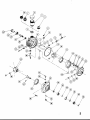
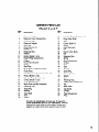
General Parts List
Model 6 and 7
Description
Item
No. Description
Reservoir Adapter
Reservoir Cover Subassembly
Reservoir Body
Reservoir Adapter
Seal Ring
Cover Service Kit
Dowel Pin
Retaining Ring
Washer
Button (Model 7 only)
Guide Fitting Subassembly
O-Ring
Dump Valve Bracket
Spring
Seal Ring
Pump Rotor and Ball Assembly
Pump Race
Cam Ring Assembly (includes No. 17)
Piston (Model 7 only)
Back-Up Ring (Model 7 only)
O-Ring (Model 7 only)
Pintle Subassembly
Motor Rotor and Ball Assembly
Retaining Ring
Snap Ring
Bearing
Input Shaft
Seal
O-Ring
30
31
32
33
34
35
36
37
38
39
40
41
42
43
44
45
46
47
48
49
50
51
52
53
54
55
56
57
Nut and Gasket Subassembly
Dump Valve Shaft
Seal
Control Shaft Kit
Dowel
Cam Ring Insert
Pin
Check Valve Body
Ball
Retaining Ring
Spring
Plug Subassembly
O-Ring
Body
Seal
Bearing
Snap Ring
Retaining Ring
Spacer
Gear
Retaining Ring
Output Shaft Subassembly
Key
Motor Race
Cap Screw
O-Ring
Plug Subassembly
Plug
This list is for identification of parts only. To insure the
correct replacement parts for your transmission, it will be
necessary to order parts by part number. Consult your
supplier for a parts list for your specific model number.
3

Contents
Product Identification and Ordering Information
Refer to specific listing covering your Eaton
transmission. Parts listings are available from the
Hydraulics Division, Minneapolis Plant.
When ordering parts, please include the following:
Model Number
Date Code
Part Number
Part Name
Quantity of Parts
Product Identification and Ordering Information
4
Exploded View
2
Part
Description 3
Disassembly-Reassembly Procedures
Body Assembly-Disassembly
Reassembly
Body/Cover-Disassembly
Reassembly
9
11
5
11
Cam
Ring-Disassembly/lnspection
6
Installation 11
Check Valves-Removal
Installation
7
8
Cover
Assembly-Disassembly/Inspection
5
Reassembly
9
Dampening Pistons-Removal
8
Installation
8
Motor Rotor Assembly-Removal
8
Installation 12
Pintle Assembly-Removal
7
Disassembly/lnspection
7
Installation 11
Pump Rotor Assembly-Removal
4
7
Installation 11
Reservoir/Adapter-Disassembly
5
Reassembly 13
Rotor
Assemblies-Disassembly/lnspection
8
Start/up Procedures
Trouble Shooting
Fluid Recommendations
C
Copyright
1982
Eaton Corporation
13
14
16
600-023
AlOA
cw
D12B
1
v
Rotation
cw
ccw
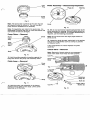
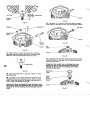
Factory Rebuild
Date Code-D12B1
Original Build
Date Code-A10A Month
1T2E
Month
-
Model Identification
600-Model
6
700-Model 7
023-Specific Unit
Configuration
Special
tools
to aid
in
Disassembly/Reassembly
2
x
6
x
10 wooden block with
Y4”
dia. hole in the
center.
2 large, wide rubber bands.
Y16-18
tap.
Light petroleum jelly (such as Vaseline).
Steel bar stock or piece of wood-2” dia.
x
2%” long.

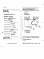
Disassembly/Reassembly
Fig.
1
Clean the transmission exterior thoroughly before
repairs are begun. Use a cleaning solution that
will
not
affect paint, gaskets, rubber seals, and plastic.
Important: When compressed air is used in
cleaning, do not expose lip seals or bearing
surfaces to high pressure.
Drain fluid from transmission.
Note:
A
2
x
6
x
10
wooden block with a
3/4
inch hole
in the center is recommended for a suitable bench
fixture.
Adapter
#1
Reservoir
Plug
I
I
i
JLl
8
Seal
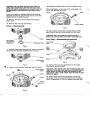
Reservoir/Adapter-Disassembly
Eaton light duty transmissions are equipped with one
of
two
adapters or a reservoir as shown in Fig.
2.
1
Remove the adapter or reservoir by rotating
clockwise.
Important: The adapters and reservoir have left
hand threads.
To
remove turn clockwise.
To
remove adapter
#1
use a six point
1½”
1/2”
hex wrench
or socket.
To
remove adapter #2 use a six point
1”
hex wrench or
socket.
To
remove the reservoir use a small filter or web
wrench.
2
Remove the seal ring from the cover and discard.
Note: We recommend that all seals be replaced with
new ones whenever the transmission is disassembled
and reassembled.
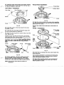
Body/Cover-Disassembly
5
Fig.
3
Important: Before disassembling the transmission,
scribe a line across the cover and body to ensure
correct reassembly. Incorrect assembly
will
change
output shaft rotation.
3
Use
1/4
inch allen wrench to remove the
(2)
5/16
cap
screws. Where applicable, remove the dump valve
shaft.
Fig.
2
4
Lift the cover to separate from the body.

Important:
Do
not allow the cam ring, pintle, or
9
Remove the button from the cover (model
7
only).
pump rotor assembly to
lift
with the cover. The
pump ball piston assembly must remain intact
as
Where applicable, remove the dump valve guide, nut,
the ball pistons are matched to the pump rotor and O-ring. Discard the O-ring.
bores.
Cove
If
the cover does not separate easily from the body
because of fluid seal, tap the body and or cover with
plastic hammer to break the seal.
5 Remove the dump valve bracket, and springs,
when used.
6
Remove the seal ring and discard.
Cover-Disassembly
and Bearing
Assembly Retaining Ring
Fig.
4
7
Remove input shaft retaining ring. Press or drive the
input shaft and bearing assembly from the cover.
Cover
Input Shaft
I
Seal
Fig.
5
6
8
Press or drive the input shaft seal from the cover.
Dump Valve
Guide
Butt
Fig.
7
10
Use a sharp, narrow tool to pierce the top metal
part of the oil seal and remove seal from the cover.
Important:
Do
not scratch
the
control shaft or
distort the seal counter bore when removing seal.
Cam
Ring-Disassembly/lnspection
Cam Ring
Assy.
Cam
Pintle
Body
Fig.
8
11
Remove the cam ring assembly from the pintle.
Remove the cam ring insert.
Important: Use special care when removing the cam
ring
from the pump rotor assembly. The ball pistons
must remain
in
place as they are matched to the
rotor bores. Use a wide rubber band to hold the ball
pistons
in
place.
12 Inspect area where the ball pistons contact the
pump race. This area must be smooth and completely
free of irregularities.
If
it is not, replace the pump race.

Pintle
Assembly-Disassembly/lnspection
Pump
Race
Fig.
9
Note:
The pump race is press fit in the cam ring and
will
require a press to remove it. The cam ring and
pump race are available as an assembly.
Note:
If
irregularities are noted in the pump race, it is
reasonable to assume that one or more ball pistons and
rotor bores
will
also be damaged.
Pump Rotor-Removal
Fig.
10
13
Hold the pintle assembly in position against the
body and remove the pump rotor assembly intact.
Pintle Assy.-Removal
Pintle
Assy.
Body
Fig.
11
14
Hold the motor rotor assembly in the bottom
position and tap lightly on the body. Lift the pintle
assembly out of the body.
Pintle
Fig.
12
15
We do not recommend complete disassembly of the
pintle assembly for cleaning. Normal flushing should
be
all that is required. However,
if
complete disassembly is
required, use the following procedures:
Note:
Do
not remove the
two
large plugs located on
pintle journal.
16
Inspect the pintle journals, particularly in the porting
area for any irregularities such as scoring or grooves
cut between ports.
If
any irregularities are noted: Replace the pintle
assembly.
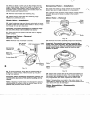
Check Valve-Removal
Note:
Removal of check valves is not necessary
if
check valve balls move freely and seat properly.
Fig.
13

17
Press or drive out the coil pin that retains the
two
check valve bodies. Use a four blade
5/16-18
tap to tap
holes in check valve bodies. Insert a long bolt or a
threaded puller, pull the check valve bodies from the
pintle housing and discard them.
18
Remove check balls and retaining ring.
19
Inspect check valve balls and retaining rings.
Replace any defective parts.
Check Valve-Installation
20
Install retaining rings and check valve balls in bores
of pintle. Press new check valve bodies in bores. Press
far enough for coil pin clearance.
Important: To prevent dislodging
of
retaining rings
do
not
drive check valve bodies into bores.
21
Press coil pin into pintle until flush with or slightly
below surface.
Dampening Piston
-
Removal
(Model
7
Only)
Note:
Remove only
if
surface is scored.
\
..
Dampening
Pistons
(2)
...
..
..
...
..
. . ..
...
1
Back-up
Rings
(2)
O-ring Seals
(2)
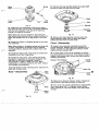
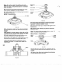
Dampening Piston-Installation
23
Install new back-up rings nearest to the smooth
piston face and O-rings in grove on a new piston.
24
Lubricate outer surface of the pistons. Press pistons
(smooth face up) in bores in pintle to the bottom
position.
Motor Rotor- Removal
I
Motor Wide
Rotor
Band
Rubber
Assy.
Body
Fig.
15
25
Remove the motor assembly intact from the body.
Important: 'Use special care when removing the
motor rotor from the body. The ball pistons MUST
remain in place as they are matched to the motor
bores. Use a wide rubber band to hold the ball
pistons in place.
8
Fig.
14
22
To
remove pistons, firmly tap the outside edge of
pintle on a work surface. Remove back-up ring and
O-ring from pistons.
Important: When dislodging dampening pistons, do
not hit pintle journals or the pintle housing
will be
ruined.
Note:
If
tapping of pintle does not dislodge the pistons,
use adhesive to cement a bolt or similar object to the
pistons and pull them from the bore.
Body
Motor Contact
Race Line
Fig.
16
26
Inspect the contact line of the motor ball pistons on
the motor race located in body. This contact area must
be smooth and completely free of any irregularities.
If
any irregularities are noted, replace the motor race.
Note:
if
irregularities are noted in the motor race, it is
reasonable to assume that one or more ball pistons and
rotor bores will also be damaged.
Rotor Assemblies-Disassembly
Inspection

Motor
Rotor
Pump
Rotor
Spring
Fig.
17
27
Inspect the rotor assemblies. Remove the piston
balls from the rotor, one at a time, by working clockwise
from the letter stamped in the face of the rotor and
placing
in
a prepared container.
31
Remove the snap ring that retains the output shaft
and tap or press the shaft from the body.
Body
Seal
Bearing
Retaining
Ring
Note:
Each ball must be replaced in the same bore Fig.
19
from which it was removed. Use a suitable container for
piston ball storage such as an egg carton or ice cube
32
Remove the large retaining ring that retains the
tray. output bearing to body. Drive or press the output
28
Inspect for broken or collapsed springs in the motor
rotor assembly.
Cover-
Reassembly
Note:
When broken or collapsed springs are found with
33
Inspect cover assembly, especially around the
no other irregularities, the springs may be replaced
control shaft area. Replace the cover assembly
if
'it is
individually without replacing the complete motor rotor
broken, cracked or
if
side clearance between control
bearing and seal from the motor body.
assembly. shaft and cover exceeds
.006.
29
Inspect the piston balls. They must be smooth and
completely free of any irregularities.
30
Inspect the rotor bores, rotor bushing and pintle
journals for irregularities or excessive clearance. The
ball piston
to
rotor bore clearance is select fit
electronically to
.0002
to
.0006
of an inch. When
irregularities or excessive clearance are noted, replace
the complete rotor assembly.
Install ball pistons in their matching bores. Hold them in
place with a rubber band.
Body
Body
output
Shaft
34
In most cases, it
will
not be necessary to remove
the control shaft from the cover.
If
the dowel is loose
or
broken in the control shaft, remove the shaft using the
following procedures.
9
Measure this Distance
A
Control
9
Fig.
20
35
Measure the distance between center of dowel pin
and the end of the shaft as shown in Figure
20.
36
Turn cover over. Use this dimension to locate dowel
pin
in
cover face. Drill
11/32”
diameter hole at center
point of dowel pin. Drill hole exactly in line with center
of shaft.
Fig.
18

measured
Fig. 21
Washer Washer
Fig. 22
37
Press loose or broken dowel pin out. Remove
retaining ring and washer from end of control shaft.
Remove control shaft outward from the cover.
10
”
Pipe Plug
Fig.
23
38
Tap hole drilled with
1/8”
pipe tap. Install
1/8”
flush
type pipe plug.
39
Lubricate a new control shaft and install in cover.
Replace washer and retaining ring on end of control
shaft. Press new dowel pin through shaft leaving
1%
inch of dowel extending from shaft.
Important: When pressing the new dowel pin into
the control shaft, the Woodruff key in control shaft
must
be
to the left looking at the threaded end of
shaft.
Cover
Fig. 24
40
Lubricate
I.D.
of new oil seal with clean lubricant.
Then press or tap seal in bore until completely seated.
Oil Seal
Cover
Fig.
25
Lip
Seal
Cover
. . . . . . . .
.
.
.
. . .
. .
.
.
.
.
.
.
Fig. 26
41
Lubricate inner surface of the lip seal with a clean
lubricant. Press or tap seal into the bottom position in
cover counter bore.
Important: Be careful not to damage the inner
portion of the oil seal. Excessive pressing or
driving of the
oil
seal will damage the rubber
portion of the seal.
Retaining
Ring
Fig.
27

42
Install the input shaft assembly into bottom position
in the counter bore in cover. Install the retaining ring in
the groove located in front cover.
Cam Ring-Installation
Cam Ring Cam Ring Insert
Pump
Rotor-Installation
Pump Rotor
Rubber Band
Cover
Fig.
30
47
Align the internal spline in the pump rotor assembly
with the external spline on the input shaft and install the
pump rotor in the cover.
Fig.
28
Remove the rubber band retaining the ball pistons (if
used).
43
Install the button in the hole located in the cover.
(In Model
7
only)
Pintle-Installation
44
Install the cam ring insert with the hole away from
the cam ring as shown in Figure
28.
45
Align the cam ring with the control shaft pin and the
cam ring pivot pin.
Install the cam ring with the flush side
of
the bearing
race facing the cover. Press in firmly until the cam ring
has bottomed in the cover assembly.
Important: Cam
ring
must move freely from stop to
stop. If
binding
occurs at either stop rotate the cam
ring
insert
180°.
Check the cam
ring
movement
again.
O-ring Dump Valve O-ring Dump Valve
Guide
\
Shaft
Fig.
29
46
Where applicable, lubricate O-Ring and install in
groove located in dump valve guide. Install guide
through cover and install O-Ring and nut. Lubricate
dump valve, valve shaft and install in guide assembly.
Note:
Check dump valve shaft for freedom
of
movement.
Fig.
31
48
Install the
two
springs and dump valve bracket into
pintle assembly.
Use a small screwdriver to compress and hold dump
valve bracket into pintle to clear previously installed
dump valve guide located
in
cover.
49
Align pintle assembly with the cam ring pivot pin
and guide pintle assembly into pump rotor. Push to
bottom position
in
cover.

Note:
Do
not force pintle through the pump rotor
assembly as it is a slip fit. The pump rotor assembly
must turn freely on the pintle by hand.
If
not recheck
pintle installation.
50
Push dump valve shaft in and thread into dump
valve bracket.
Torque to
2-3
Foot Pounds.
Retaining
51
Lightly grease new cover sealing ring and install in
the groove in the cover.
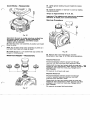
Body-Reassembly
Lip Seal
Fig.
34
54
Install output shaft bearing by positioning bearing
over output shaft and pressing on outer race of ball
bearing to the bottom position in body.
55 Install small snap ring on output shaft against inner
bearing race.
Body
Fig.
32
52
Lubricate inner surface of new lip seal and install
with the rubber lip
of
the seal toward the counter bore
in body.
Important:
Do
not over press
or
drive the
seal,
this
may damage the rubber sealing portion
of
the seal
or
distort counter bore.
53
Install output shaft into body, protecting the shaft
seal lip from keyway and snap ring grooves.
Support the output shaft from underneath body
so
that
the cross pin in output shaft is tight against body.
Use a solid block (steel or hardwood)
2
inches in
diameter by at least
1%
inches long to support the
output shaft.
56 Install the large retaining ring used to retain ball
bearing in body.
Note:
The output shaft must rotate freely by hand.
If
it
doesn't, recheck bearing installation.
Motor Rotor-Installation
Motor
Wide
Rotor Rubber
Assy. Band
I
a
12
Fig.
35
57
Align the slot in the motor rotor assembly with the
cross pin on the output shaft and install the motor rotor
in
body.
58
Remove the rubber band retaining the ball pistons
in their respective bores (if used).
Fig.
33

Cover/Body-Reassembly
Fig.
36
Important: Be sure to realign previous scribed line
for correct ouput rotation.
If
body assembly
is
installed 180° as previous assembled output
rotation
will
be reversed.
59
Hold the motor rotor assembly in position and install
body on pintle.
Note:
Do
not force motor rotor assembly on pintle as it
is
a slip fit and must turn freely by hand.
60
Install the
(2)
5/16
x
1
1/4
socket heat cap screws and
torque to
15
foot pounds.
Reservoir/Adapter-Reassembly
I
61
Lightly grease sealing ring and install into recess
in cover.
62
Install the adapter or reservoir in cover by rotating
counterclockwise.
Torque to Approximately 8-12 ft. Ibs.
Important: The adapters and reservoir are threaded
left hand. To install, turn counterclockwise.
Start-up Procedure
i
Fig.
38
63
Remove the
3/8
hex head plug to vent the
transmission. See Page
16
for fluid recommendations.
Attached Reservoir
Fill the transmission with the proper fluid through
reservoir until fluid overflows from opening in body.
Rotate both the input and output shafts to purge any
trapped air from transmission. Refill reservoir until fluid
13
reappears and install hex head plug,
Torque to 2-5
Foot Pounds.
Fill reservoir to oil level cold mark.
Separate Reservoir
Fill the transmission with the proper fluid through
customer supplied separate reservoir until fluid
overflows from opening in body.
Rotate both the input and output shafts to purge any
trapped air from transmission. Refill reservoir until fluid
reappears and install hex head plug.
Torque to 2-5
Foot Pounds.
Fill reservoir to proper fluid level shown.
Fig.
37

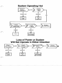
Trouble Shooting Instructions
This fault-logic troubleshooting section is designed as a
diagnostic aid in locating transmission problems by the
user.
Match the transmission problem with the problem
statements and follow the action steps shown in the
diagrams. This will give the user expedient aids in
correcting the problem and eliminating unnecessary
machine down time.
System
I
I
Inspect
14
Jerky When Starting
External Control
Linkage
Transmission
I
Defective
I
I
Defective
I
Serviceable
Replace Externally
System Operates in One Direction Only
External
Control Linkage
Defective
Defective
Serviceable
Externally

f-'
System Operating
Hot
Transmission Check Oil
I
Below Level
I
Proper
Level
OK
Clogged
I
Clean
Defective
Serviceable
Externally
Loss
of
Power
or
System
Will
Not Operate in Either Direction
OK
15
Below Level Defective Defective

EATON
HYDROSTATIC TRANSMISSION
MODEL
6/
7
REPAIR MANUAL
NO.
7-403
Hydrostatic Fluid Recommendations
A reputable supplier can help you make the best selection of
hydraulic fluid for use in Eaton hydrostatic products.
For
satisfactory operation, the following recommendations
1.
The filter system used in the hydraulic circuit should be
apply:
capable of cleaning and maintaining the hydraulic fluid
to
meet
ISO
Cleanliness Code 18/13 per SAE J1165. This code
allows a maximum of 2500 particles per milliliter greater than
5
µm
and a maximum of 80 particles per milliliter greater than
15 µm.
2.
At normal operating temperatures, optimum viscosity ranges
are from 80-180
SUS
(16-39 cSt). Viscosity should never fall
below
60
SUS
(10 cSt) and, at the lowest expected start-up
temperature, should not exceed
10,000
SUS
(2158 cSt).
3.
The fluid should be chemically stable, incorporating rust and
oxidation inhibitors.
Specific types of fluid meeting these requirements are:
Premium hydraulic oil'
Engine crankcase oil-SAE 1 Ow, SAE
2Ow-20,
SAE
30
Automatic transmission oil
Hydraulic transmission oil
Synthetic fire resistant fluid-
Quintolubric 822-220,
-300
or -450
Quaker Chemical Co.
Conshohocken, PA 19428
Cosmolubric HF-122, -130, -1 44 or -1 530
E.F.
Houghton
&
Co.
Valley Forge, PA
Milisafe Code 1274 (280 Series) 280-1 50, -300 or -500
Future Trend Industries
Cottage Grove,
MN
55016
Note:
If
the
natural color of the fluid has become black or milky, it
is possible that an overheating or water contaminant problem
.
exists.
For accurate level readings, take readings when the fluid is cold.
*Supplied in Model
6
and
7
Transmissions, Model
750
and
770
Transaxles, and
780
Transaxles without charge pumps that are
shipped from the Spencer factory. The viscosity of this factory
fluid is equivalent to
SAE
2Ow-20.
The preferred fluids for all light
duty transmissions, pumps, transaxles and motor axles are those
having a viscosity equivalent to
SAE
2Ow-20,
SAE
30
or
SAE
40.
Eaton Corporation Hydraulics Division
151
51
Highway
5
Eden Prairie,
MN
55344
Telephone
(61
2)
937-9800
.
REVISED
OCTOBER,
1988
FORM
NO.
7-403-108
-
 1
1
-
 2
2
-
 3
3
-
 4
4
-
 5
5
-
 6
6
-
 7
7
-
 8
8
-
 9
9
-
 10
10
-
 11
11
-
 12
12
-
 13
13
-
 14
14
-
 15
15
-
 16
16
-
 17
17


Toro 940 Electric Tractor User manual
- Type
- User manual
- This manual is also suitable for
Ask a question and I''ll find the answer in the document
Finding information in a document is now easier with AI
Related papers
-
Toro ProLine 118 User manual
-
-
-
Toro 616-Z Tractor User manual
-
-
Toro 16-38HXLE Lawn Tractor User manual
-
Toro Z Master Professional 7500-D Series Riding Mower, With 144in TURBO FORCE Rear Discharge Mower User manual
-
Toro 52in Z Master 4000 Series Riding Mower User manual
-
Toro ProLine 118 User manual
Other documents
-
Snapper 1600, 1650, 1855 Series User manual
-
Ransomes 67016, 67017 User manual
-
Simplicity 1600 Series User manual
-
Kubota L295 Shop Manual
-
Eaton Vickers PVE21 User manual
-
MerCruiser 350 CID (5.7L) User manual
-
New Holland LS160 User manual
-
Chevrolet 1967 Chevelle Overhaul Manual
-
Shibaura SXM60 Workshop Manual
-
MTD 131-764A User manual