IS26700T Rev-A
USE ONLY HAYWARD GENUINE REPLACEMENT PARTS 1
Super Pump
®
700 Series
Owner’s Manual
IMPORTANT SAFETY INSTRUCTIONS
Basic safety precautions s
h
ou
ld
a
l
ways
b
e fo
ll
owe
d
, inc
l
u
d
ing t
h
e fo
ll
owing: Fai
l
ure to fo
ll
ow instructions
can cause severe injury and/or death.
This is the safety-alert symbol. When you see this symbol on your equipment or in this manual, look for
one of the following signal words and be alert to the potential for personal injury.
WARNING warns about hazards that could cause serious personal injury, death or major property
damage and if ignored presents a potential hazard.
CAUTION warns about hazards that will or can cause minor or moderate personal injury and/or
property damage and if ignored presents a potential hazard. It can also make consumers aware of
actions that are unpredictable and unsafe.
The NOTICE label indicates special instructions that are important but not related to hazards.
Hayward Pool Products
620 Division Street, Elizabeth, NJ 07207
Phone: (908) 355-7995
www.hayward.com
Contents
Product Specific Warnings………2
Introduction……….………………..…4
Installation……….……………..….….7
Shaft Seal Replacement..………..8
Replacement Parts………….……..10
Troubleshooting………….…..…….11
Warranty…………………………………13
Registration ……………………..……15

WAR
N
F
a
WAR
N
Suction in
s
severe inju
Hair Entra
Limb Entr
a
cracked, m
Body Suc
t
Eviscerati
sump or s
u
disembow
e
Mechanic
opening of
WAR
N
o
W
b
e
a
p
o D
o D
o T
h
o N
o R
e
o I
n
g
u
o I
n
WAR
N
suction o
u
WAR
N
material c
a
WAR
N
replaced
a
CAU
T
being use
d
on this pro
positioned
WAR
N
start up, n
o
follow safe
and clamp
pool and s
p
be in open
back to th
e
open filter
is dischar
g
WAR
N
of pump a
n
servicing p
circulation
circulation
circulatio
n
air can cau
high volu
m
N
ING
–
Rea
d
a
ilure to follo
w
N
ING
– Suct
s
uction outlets
ry and/or deat
h
pment
- Hair c
a
a
pment
- A lim
b
issing, or not s
t
ion Entrapm
e
on/ Disembo
w
u
ction outlet co
v
e
lment.
a
l Entrapmen
a suction outl
e
N
ING
- To Re
W
hen outlets ar
e
e
installed. Su
c
p
art, as measu
r
ual suction fitt
i
ual suction fitt
i
h
e maximum s
y
ever use Pool
o
e
place damag
e
n
addition two
o
u
idelines, follo
w
n
stallation of a
v
N
ING
– Failu
u
tlets can resu
N
ING
– Failu
a
n result in an
N
ING
– Suct
i
a
t least every s
T
ION
– Comp
d
as means of
d
uct. Closely
s
to prevent chil
N
ING
– Haz
a
o
rmal operatio
n
ty and operati
o
due to pressur
e
p
a water circul
a
position. Befo
e
pool. Do not
c
manual air reli
e
ed.
N
ING
– Sep
a
n
d/or filter com
ool and spa cir
system if a sys
system unless
n
system at m
o
se component
s
m
e blower when
USE ONL
Y
d
, understa
n
w
instructions
c
ion Entrapm
e
and/or suctio
n
h
due to the fol
a
n become ent
a
b
inserted into
ecurely attach
e
e
nt
- A negative
w
elment
- A n
e
v
er which is, d
a
t
- There is pot
e
e
t cover resulti
n
duce the ris
k
e
small enough
c
tion outlets in
r
ed from near
p
ngs shall be pl
ngs shall not b
y
stem flow rate
o
r Spa if any su
c
e
d, broken, cra
c
o
r more suction
w
all National,
v
acuum releas
e
re to remove
p
lt in an increa
s
re to keep suc
increase pot
e
i
on outlet com
even years or
onents such a
access to the
upervise child
r
dren from usin
g
a
rdous Press
u
n
, and after pu
m
o
n instructions
e
in the system
a
tion system, a
re starting sys
t
c
hange filter co
e
f valve. Do no
a
ration Haza
r
ponents. Strai
culation syste
m
tem compone
n
filter manual a
o
re than 50 PS
I
s
to explode, w
i
air purging th
e
Y
HAYWARD G
n
d, and fol
l
c
an cause sev
e
e
nt Hazard.
n
outlet covers
w
lowing entrap
m
a
ngled in sucti
o
an opening of
a
e
d can result in
pressure appli
e
gative pressu
r
a
maged, broke
n
e
ntial for jewelr
y
n
g in mechanic
a
k
of Entrapm
e
to be blocked
the same plan
p
oint to near po
aced in such l
o
e located on s
e
shall not exce
e
c
tion outlet co
m
c
ked, missing,
o
outlets per pu
m
State, and Loc
a
e
or vent syste
m
p
ressure test p
s
e potential f
o
tion outlet co
m
e
ntial for sucti
o
ponents have
if found to be
s the filtratio
n
pool by young
r
en at all times
.
g
them as a m
e
u
re.
Pool and
m
p shut off. St
a
could result in
, which could
c
ll system and
p
em pump, all s
ntrol valve pos
t close filter m
a
r
d. Failure to f
o
ner cover must
m
, filters manu
a
n
t is not assem
b
ir relief valve b
I
. Do not purg
e
i
th risk of seve
r
e
pump, filter,
o
ENUINE REPL
A
l
ow all inst
r
e
re injury and
/
w
hich are, da
m
m
ent hazards:
o
n outlet cover
.
a
suction outle
t
a mechanical
b
e
d to a large p
o
r
e applied dire
c
n
, cracked, mis
y
, swimsuit, ha
a
l entrapment.
e
nt Hazards:
by a person, a
m
e (i.e. floor or
w
int.
o
cations and di
s
e
ating areas or
e
d the flow rati
n
m
ponent is da
m
o
r not securely
m
p installed in
a
l codes applic
a
m
, which reliev
e
lugs and/or p
l
o
r suction entr
a
m
ponents cle
a
o
n entrapmen
t
a finite life, t
h
damaged, bro
n
system, pum
p
children. To
r
.
Components
s
e
ans of access
t
spa water circ
u
a
nd clear of cir
c
violent separa
t
c
ause property
p
ump controls
m
ystem valves
m
ition while sys
t
a
nual air relief
v
o
llow safety an
be properly se
a
l air relief valv
b
led properly,
d
ody is in locke
d
e
the system
w
r
e injury or dea
t
o
r piping.
A
CEMENT PA
R
r
uctions
in t
h
/
or death.
m
aged, broken,
.
t
sump or sucti
o
b
ind or swellin
g
o
rtion of the bo
c
tly to the intes
s
sing, or unsec
u
a
ir decorations,
minimum of tw
w
all), must be i
stances to avo
i
on the backre
s
n
g of as listed
o
m
aged, broken,
attached sucti
o
accordance w
i
able.
e
s entrapping
s
lugs used in
w
a
pment as de
s
a
r of debris, s
u
t
as described
h
e cover/grate
ken, cracked,
ps and heater
r
educe risk of i
n
such as the filt
t
o the pool.
u
lation system
s
c
ulation syste
m
t
ion of the pum
damage, seve
r
m
ust be in off
p
m
ust be set in a
t
em pump is ru
v
alve until a st
e
d operation in
s
cured to pump
e must be in o
p
d
amaged, or m
i
d
position in fil
w
ith compress
e
t
h to anyone n
e
R
TS
his owner’s m
a
cracked, missi
on outlet cove
r
g
of the limb.
o
dy or limbs ca
n
tines through
a
u
red can result
finger, toe or
k
w
o functioning
s
nstalled a mini
i
d “dual block
a
s
t for such seat
i
o
n Table 1.
cracked, miss
i
o
n outlet comp
i
th latest ASM
E
s
uction, is reco
w
interization o
f
s
cribed above
.
u
ch as leaves,
above.
should be in
s
missing, or n
o
must be posi
t
n
jury, do not p
e
ration system,
s
operate unde
r
m
equipment d
u
p housing and
r
e personal inj
u
p
osition and fil
t
position to all
o
nning. Before
s
e
ady stream of
s
tructions coul
d
housing with
s
p
en position.
D
i
ssing. Do not
o
ter upper body
ed air. Purgin
g
e
arby. Use onl
y
a
nual and on
t
ng, or unsecur
e
r
that is damag
e
n
result in an e
n
a
n unprotected
in evisceratio
n
k
nuckle to be c
a
s
uction outlets
mum of three
f
a
ge” by a user.
i
ng areas.
i
ng, or not sec
u
onents immed
i
E
, APSP Standa
r
mmended.
f
the pool/spa
.
dirt, hair, pap
s
pected frequ
e
o
t securely att
a
t
ioned so as t
o
e
rmit children t
o
pumps, and h
e
r
hazardous pr
e
u
ring pump sta
cover, and/or
f
u
ry, or death. B
t
er manual air r
o
w system wat
e
s
tarting syste
m
water
(
not air
o
d
result in viole
s
trainer cover l
o
D
o not operate
p
o
perate pool a
n
. Never opera
t
g
the system wi
y
a low pressur
t
he equipmen
t
e
d can cause
e
d, broken,
n
trapment.
suction outlet
n
/
a
ught in an
per pump mus
t
f
eet (3’) [1 met
e
u
rely attached.
i
ately.
r
ds and CPSC
from the
er and other
e
ntly and
a
ched.
o
prevent their
o
use or climb
e
aters must be
e
ssure during
rt up. Failure t
o
f
ilter housing
efore servicing
elief valve mu
s
e
r to return
m
pump, fully
o
r air and wate
r
e
nt separation
o
ck ring. Befor
e
p
ool and spa
n
d spa
t
e or test the
th compresse
d
e (below 5 PSI)
2
t
.
t
e
r]
o
t
r
)
e
,

USE ONLY HAYWARD GENUINE REPLACEMENT PARTS 3
WARNING – Risk of Electric Shock. All electrical wiring MUST be in conformance with applicable local codes,
regulations, and the National Electric Code (NEC). Hazardous voltage can shock, burn, and cause death or serious property
damage. To reduce the risk of electric shock, do NOT use an extension cord to connect unit to electric supply. Provide a properly
located electrical receptacle. Before working on any electrical equipment, turn off power supply to the equipment. To reduce
the risk of electric shock replace damaged wiring immediately. Locate conduit to prevent abuse from lawn mowers, hedge
trimmers and other equipment. Do NOT ground to a gas supply line.
WARNING – Risk of Electric Shock Failure to ground all electrical equipment can cause serious or fatal electrical shock
hazard. Electrical ground all electrical equipment before connecting to electrical power supply.
WARNING – Risk of Electric Shock Failure to bond all electrical equipment to pool structure will increase risk for
electrocution and could result in injury or death. To reduce the risk of electric shock, see installation instructions and consult a
professional electrician on how to bond all electrical equipment. Also, contact a licensed electrician for information on local
electrical codes for bonding requirements.
Notes to electrician: Use a solid copper conductor, size 8 or larger. Run a continuous wire from external bonding lug to
reinforcing rod or mesh. Connect a No. 8 AWG (8.4 mm
2
) [No. 6 AWG (13.3 mm
2
) for Canada] solid copper bonding wire to the
pressure wire connector provided on the electrical equipment and to all metal parts of swimming pool, spa, or hot tub, and metal
piping (except gas piping), and conduit within 5 ft. (1.5 m) of inside walls of swimming pool, spa, or hot tub.
IMPORTANT - Reference NEC codes for all wiring standards including, but not limited to, grounding, bonding and other general
wiring procedures.
WARNING – Risk of Electric Shock . The electrical equipment must be connected only to a supply circuit that is protected
by a ground-fault circuit-interrupter (GFCI). Such a GFCI should be provided by the installer and should be tested on a routine
basis. To test the GFCI, push the test button. The GFCI should interrupt power. Push reset button. Power should be restored. If
the GFCI fails to operate in this manner, the GFCI is defective. If the GFCI interrupts power to the electrical equipment without the
test button being pushed, a ground current is flowing, indicating the possibility of an electrical shock. Do not use this electrical
equipment. Disconnect the electrical equipment and have the problem corrected by a qualified service representative before
using.
CAUTION – HAYWARD
®
pumps are intended for use with permanently-installed pools and may be used with hot tubs and
spas if so marked. Do not use with storable pools. A permanently-installed pool is constructed in or on the ground or in a
building such that it cannot be readily disassembled for storage. A storable pool is constructed so that it is capable of being
readily disassembled for storage and reassembled to its original integrity.
WARNING – Risk of Hyperthermia. To avoid hyperthermia the following “Safety Rules for Hot Tubs” are recommended by
the U.S. Consumer Product Safety Commission.
1. Spa or hot tub water temperatures should never exceed 104°F [40°C]. A temperature of 100°F [38°C] is
considered safe for a healthy adult. Special caution is suggested for young children. Prolonged immersion
in hot water can induce hyperthermia.
2. Drinking of alcoholic beverages before or during spa or hot tub use can cause drowsiness, which could
lead to unconsciousness and subsequently result in drowning.
3. Pregnant women beware! Soaking in water above 100°F [38°C] can cause fetal damage during the first
three months of pregnancy (resulting in the birth of a brain-damaged or deformed child). Pregnant women
should adhere to the 100°F [38°C] maximum rule.
4. Before entering the spa or hot tub, users should check the water temperature with an accurate ther-
mometer; spa or hot tub thermostats may err in regulating water temperatures by as much as 4°F
(2.2°C).
5. Persons taking medications, which induce drowsiness, such as tranquilizers, antihistamines or anti-
coagulants, should not use spas or hot tubs.
6. If the pool/spa is used for therapy, it should be done with the advice of a physician. Always stir pool/ spa water
before entering the pool/spa to mix in any hot surface layer of water that might exceed healthful temperature
limits and cause injury. Do not tamper with controls, because scalding can result if safety controls are not in
proper working order.
7. Persons with a medical history of heart disease, circulatory problems, diabetes or blood pressure
problems should obtain a physician’s advice before using spas or hot tubs.
8. Hyperthermia occurs when the internal temperature of the body reaches a level several degrees above normal
body temperature of 98.6°F [37°C]. The symptoms of Hyperthermia include: drowsiness, lethargy,
dizziness, fainting, and an increase in the internal temperature of the body.
The effects of Hyperthermia include:
1. Unawareness of impending danger.
2. Failure to perceive heat.
3. Failure to recognize the need to leave the spa.
4. Physical inability to exit the spa.
5. Fetal damage in pregnant women.
6. Unconsciousness resulting in danger of drowning.
SAVE THESE INSTRUCTIONS

USE ONLY HAYWARD GENUINE REPLACEMENT PARTS 4
General Information
Introduction
This manual contains information for the proper installation and operation of the Hayward Super Pump
®
700 Series.
The instructions in this manual MUST be followed precisely. Failure to install according to defined instructions
will void warranty.
Product Benefits
Super-sized 110 cubic-inch basket has extra leaf-holding capacity and extends time between cleanings. Rigid
construction with load extender ribbing assures free flowing operation even with heavy debris loads.
Exclusive swing-aside hand knobs make strainer cover removal simple and easy.
See-thru strainer cover lets you see when the basket needs cleaning.
All components molded of corrosion-proof reinforced thermoplastic for extra durability and long life.
Uni-bracket mounting base provides stable, stress-free support, plus versatility for any installation requirement.
Adapts to 48 and 56 frame motors.
Heat resistant, industrial size ceramic seal.
Rugged, one-piece housing, with full-flow ports, assures rapid priming and continuous operation.
Service-ease design gives simple access to all internal parts. By disengaging just four (4) bolts, motor and
entire drive group assembly can be removed, without disturbing pipe or mounting connections.
Product Specifications
Installation Instructions
NOTICE
– This product should be installed and serviced only by a qualified professional.
Pump Location
Locate pump as close to pool as practical and run suction lines as direct as possible to reduce
friction loss. Suction lines should have continuous slope upward from lowest point in line.
Joints must be tight (but not over-tightened). Suction line diameter must equal or be larger than
the discharge line diameter.
Though the pump is designed for outdoor use, it is strongly advised to protect the electrical components from the
weather. Select a well-drained area, one that will not flood when it rains. Do NOT install pump in a damp or non-
ventilated location. Keep motor clean. Pump motors require free circulation of air for cooling.

USE ONLY HAYWARD GENUINE REPLACEMENT PARTS 5
Pump Mounting
Install pump on a firm, level base or pad to meet all local and national codes. Fasten pump to base or pad with
screws or bolts to reduce vibration and stress on pipe or hose joints. The base MUST be solid, level, rigid, and
vibration free.
Pump mount must:
Allow pump inlet height to be as close to water level as possible.
Allow use of short, direct suction pipe (to reduce friction losses).
Allow for ball valves in suction and discharge piping.
Be protected from excess moisture and flooding.
Allow adequate access for servicing pump and piping.
Incorporate a straight portion of pipe prior to pump inlet no less than (5) pipe diameters in length.
Pipe Sizing Chart
MAXIMUM RECOMMENDED SYSTEM FLOW RATE BY PIPE SIZE
Pipe Size Flow rate Water Velocity Pipe Size Flow rate Water Velocity
inches [mm] GPM [Liter/Min] ft/sec [meters/sec] inches [mm] GPM [Liter/Min] ft/sec [meters/sec]
1 ½” 50.76 8 2 ½” 119 8
[50] [192] [2.44] [75] [452] [2.44]
2” 84 8 3” 184 8
[63] [317] [2.44] [90] [698] [2.44]
NOTE – System design should allow a maximum of 8-ft/sec [2.44 meters/sec] water velocity in residential pool or spa
piping. It is recommended that a minimum length of piping, equivalent to 10 pipe diameters, be used between the
pump suction inlet and any plumbing fittings.
Plumbing
Use PTFE tape to seal threaded connections on molded plastic components. All plastic fittings must be new or
thoroughly cleaned before use. NOTE - Do NOT use Plumber’s Pipe Dope as it may cause cracking of the plastic
components.
When applying PTFE tape to plastic threads, wrap the entire threaded portion of the male fitting with one to two
layers of tape. Wind the tape clockwise as you face the open end of the fitting, beginning at the end of the fitting.
The pump suction and outlet ports have molded-in thread stops. Do NOT attempt to force hose connector fitting
past this stop. It is only necessary to tighten fittings enough to prevent leakage. Tighten fitting by hand and then
use a tool to engage fitting an additional 1 ½ turns. Use care when using PTFE tape as friction is reduced
considerably; do NOT over-tighten fitting or you may cause damage. If leaks occur, remove connector, clean off
old PTFE tape, re-wrap with one to two additional layers of PTFE tape, and re-install connector.
Fittings
Fittings restrict flow. For better efficiency, use the fewest possible fittings. Avoid fittings that could cause an air
trap. Use two or more suction outlets per pump installed in accordance with latest ASME, APSP Standards and CPSC
guidelines, follow all National, State, and Local codes applicable.
Electrical
NOTICE – All wiring must be done by a licensed electrician and must conform to all local and national codes
and regulations.
WARNING – Risk of Electric Shock. Before working on any electrical equipment, turn off power supply to the
equipment.
WARNING – Fire Hazard. Match supply voltage to motor nameplate voltage.
Insure that the electrical supply available agrees with the motor’s voltage, phase, and cycle, and that the wire size is
adequate for the HP (kW) rating and distance from the power source. NOTE - All electrical wiring MUST be
performed by a licensed electrician, and MUST conform to local codes and NEC regulations
.

USE ONLY HAYWARD GENUINE REPLACEMENT PARTS 6
Use copper conductors only.
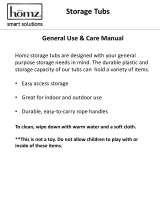
This pumps has two power source wiring options, 115V or 230V. The pump comes already wired for 230V from the factory.
To switch the pump to accept 115V power source , simply pull the connector plug that has the single blue looped wire
(230V) and replace it with the connector plug that has the three looped brown wires (115V).
Use single blue loop wire connector for 230V Use three looped brown wire connector for 115V
Connect either 230V or 115V power source with “Faston” connectors or unsheathed wires. Connect L1 wire to location
marked “V” and connect L2 wire to location marked “W” as shown below.
For “Faston” connectors L1 L2
For unsheathed wires L1 L2
Voltage
Voltage at motor MUST NOT be more than 10% above or below motor name plate rated voltage, or motor may
overheat, causing overload tripping and reduced component life. If voltage is less than 90% or more than 110% of
rated voltage when motor is running at full load, consult Power Company.
Grounding And Bonding
Install, ground, bond, and wire motor in accordance with local or national electrical code requirements.
Permanently ground motor. Use green ground terminal provided under motor canopy or access place; use size and
type wire required by code. Connect motor ground terminal to electrical service ground.
Bond motor to pool structure. Bonding will connect all metal parts within and around the pool with a continuous
wire. Bonding reduces the risk of a current passing between bonded metal objects, which could potentially cause
electrical shock if grounded or shorted. Reference NEC codes for all wiring standards including, but not limited
to, grounding, bonding and general wiring procedures.
Use a solid copper conductor, size 8 or larger. Run wire from external bonding lug to reinforcing rod or mesh.
Connect a No. 8 AWG (8.4 mm
2
) solid copper bonding wire to the pressure wire connector provided on the motor
housing and to all metal parts of swimming pool, spa, or hot tub, and to all electrical equipment, metal piping
(except gas piping), and conduit within 5 ft. (1.5 m) of inside walls of swimming pool, spa, or hot tub.

USE ONLY HAYWARD GENUINE REPLACEMENT PARTS 7
Wiring
NOTICE – A licensed electrician must do all wiring.
Pump MUST be permanently connected to circuit. If other lights or appliances are also on the same circuit, be
sure to add their amp loads before calculating wire and circuit breaker sizes. Use the load circuit breaker as the
Master On-Off switch.
Install a Ground Fault Circuit Interrupter (GFCI) in circuit; it will sense a short-circuit to ground and disconnect power
before it becomes dangerous to pool users. For size of GFCI required and test procedures for GFCI, see
manufacturer’s instructions. Pump MUST be permanently connected to GFCI. In case of a power outage, check GFCI
for tripping, which will prevent normal pump operation. Reset if necessary.
Start-Up & Operation
WARNING – Separation Hazard – Failure to Open all suction and discharge valves could result in severe
personal injury. To avoid OPEN all suction and discharge valves, as well as filter air relief valve (if available) on
filter, when starting the circulating pump system.
Starting/Priming the Pump:
Pumps with single speed motors are self priming to 10 ft. and pumps with 2 speed motors are self priming to 10 ft. on
high speed only. Fill strainer housing with water to suction pipe level. If water leakage occurs from anywhere on the
pump or filter, DO NOT start the pump. If no leakage occurs, stand at least 10 feet from pump and/or filter and
proceed with starting the pump.
WARNING – Separation Hazard- Failure to do wait to close filter manual air relief valve until a steady stream of water (not air
or air and water) is discharged from valve could result in severe personal injury. To avoid wait for a steady stream of water.
NOTICE – NEVER OPERATE THE PUMP WITHOUT WATER. Water acts as a coolant and lubricant for the mechanical
shaft seal. NEVER
run pump dry. Running pump dry may damage seals, causing leakage, flooding, and voids
warranty. Fill strainer housing with water before starting motor.
NOTICE – Do NOT add chemicals to pool/spa system directly in front of pump suction. Adding undiluted
chemicals may damage pump and voids warranty.
NOTICE – Before removing strainer cover:
1. STOP PUMP before proceeding.
2. CLOSE VALVES in suction and outlet pipes.
3. RELEASE ALL PRESSURE from pump and piping system using filter manual air relief valve. See filter
owner’s manual for more details.
4. If water source is higher than the pump, pump will prime itself when suction and outlet valves are
opened. If water source is lower than the pump, unscrew and remove strainer cover; fill strainer
housing with water.
5. Clean and lubricate strainer cover O-ring with "Jack's 327" each time it is removed. Inspect O-ring and
re-install on strainer cover.
6. Replace strainer cover on strainer housing; turn strainer cover hand knobs clockwise to tighten cover.
NOTE - Tighten strainer cover knobs by hand only (no wrenches).
7. OPEN VALVES in suction and outlet pipes.
Before re-starting pump, see “Starting/Priming the Pump” instructions.
NOTICE – Wait five (5) seconds before re-starting pump. Failure to do so may cause reverse rotation of motor and
consequent serious pump damage.
Turn on power and wait for pump to prime, which may take up to five (5) minutes. Priming time will depend on
vertical length of suction lift and horizontal length of suction pipe. If pump does NOT prime within five minutes, stop
motor and determine cause. Be sure all suction and discharge valves are open when pump is running. See
Troubleshooting Guide.

USE ONLY HAYWARD GENUINE REPLACEMENT PARTS 8
Maintenance
Clean strainer basket regularly. Do NOT strike basket to clean. Inspect strainer cover gasket regularly and
replace as necessary.
Hayward pumps have self-lubricating motor bearings and shaft seals. No lubrication is necessary.
Keep motor clean. Insure air vents are free from obstruction to avoid damage. Do NOT use water to hose off
motor.
Occasionally, shaft seals must be replaced, due to wear or damage. Replace with genuine Hayward seal
assembly kit. See “Shaft Seal Change Instructions” in this manual.
Storage/Winterization
WARNING – Separation Hazard. Purging the system with compressed air can cause components to
explode, with risk of severe injury or death. To avoid, do not purge the system with compressed air. Use only a low
pressure (below 5 PSI), high volume blower when air purging the pump, filter, or piping.
NOTICE – Allowing the pump to freeze will void the warranty.
NOTICE
–Use ONLY propylene glycol as antifreeze in your pool/spa system. Propylene glycol is non-toxic and will
not damage plastic system components; other anti-freezes are highly toxic and may damage plastic components in
the system.
Drain all water from pump and piping when expecting freezing temperatures or when storing pump for a long time
(see instructions below).
Keep motor dry and covered during storage. To avoid condensation/corrosion problems, do NOT cover or wrap pump
with plastic film or bags.
Storing Pump for Winterization
WARNING – Electrical Hazard - Failure to disconnect power may result in serious personal injury or
death. To avoid, turn OFF power to motor before draining pump.
1. Drain water level below all inlets to the pool.
2. Remove drain plugs from bottom of strainer body, and remove strainer cover from strainer housing.
3. Disconnect pump from mounting pad, wiring system (after power has been turned OFF), and piping system.
4. Once the pump is drained of water, re-install the strainer cover and drain plugs. Store pump in a dry area.

USE ONLY HAYWARD GENUINE REPLACEMENT PARTS 9
Shaft Seal Change Instructions
IMPORTANT SAFETY INSTRUCTIONS
PLEASE READ AND FOLLOW ALL INSTRUCTIONS
WARNING – Electrical Hazard - Failure to disconnect power may result in serious personal injury or
death. To avoid, turn OFF power to motor before servicing pump.
NOTICE- Only qualified personnel should attempt rotary seal replacement. Contact your local authorized
Hayward Dealer or service center if you have any questions.
Exercise extreme care in handling both the rotating and the stationary sections of the two-part replacement seal. Foreign
matter or improper handling will easily scratch the graphite and ceramic sealing surfaces.
Removing the Motor Assembly (See Parts Diagram on page 9 of this manual for pump component locations.)
1. Remove the four (4) 3/8" x 2" housing cap screws which hold the motor assembly to the
pump/strainer housing.
2. Slide the motor assembly out of the pump/strainer housing, exposing the diffuser. Pull the diffuser
off of the seal plate, exposing the impeller. (The diffuser may remain in the pump/strainer housing.
To remove, pull it straight out of the pump/strainer housing.)
Removing the Impeller (See Parts Diagram on page 9 of this manual for pump component locations.)
3. Remove the motor end cover by removing the two (2) screws or pry off the cap covering the motor shaft.
Hex shaped caps must be twisted off.
4. To prevent motor shaft from turning, carefully slide a 7/16" open-end wrench between the capacitor and
the centrifugal switch (the wrench fits over the two (2) flats on the motor shaft). Some motors may
require a larger wrench be placed in slot at end of shaft to keep motor shaft from turning.
5. Rotate the impeller counterclockwise and remove. The spring portion of the seal assembly is now
exposed. Note carefully the position of the spring seal, and remove it. NOTE - Replace motor cover to
protect delicate motor parts.
Removing the Ceramic Seat (See Parts Diagram on page 9 of this manual for pump component locations.)
6. Remove the seal plate. Note the tabs on the sides of the plate and the mating grooves on the front of
the motor mounting plate.
7. Press the ceramic seat with rubber cup out of the seal plate. If tight, use a small screwdriver to tap seal
out.
STOP - Clean all recesses & parts to be reassembled. Inspect gaskets & replace if necessary.
Seal Installation (See Parts Diagram on page 9 of this manual for pump component locations.)
8. Clean and lightly lubricate the impeller hub and seal recess in the seal plate with a dilute solution of
non-granulated liquid-type soap.
9. Gently wipe the black, polished surface of the spring seal assembly with a clean, soft, cotton cloth.
Press the spring seal assembly onto the impeller hub – black polished surface facing away from the
impeller.
10. Gently wipe the polished surface of the ceramic seal with a clean, soft, cotton cloth. Lubricate the
rubber cup on the ceramic seat and press it firmly and evenly into the recess of the seal plate –
polished side facing out.
Replacing the Impeller and Diffuser (See Parts Diagram on page 9 of this manual for pump component locations.)
11. Place the seal plate onto the motor mounting plate, aligning the tabs on the seal plate with the
grooves on the motor mounting plate.
12. Screw the impeller onto the motor shaft in a clockwise direction. Tighten snugly by holding motor shaft
with wrench as noted in step #4.
13. Place the diffuser over the impeller onto the seal plate fitting positioning lug between the two (2) guides.
Replacing the Motor Assembly (See Parts Diagram on page 9 of this manual for pump component locations.)
14. Fasten motor end cover by using the two (2) hex shaped screws. Slide the motor assembly with the
diffuser in place, into pump/strainer housing, being careful not to disturb the diffuser gasket.
15. Fasten assembly to pump/strainer housing using the four (4) 3/8”" x 2" housing cap screws. (Be sure
housing gasket is in place, and replace if damaged). Tighten alternately and evenly.

USE ONLY HAYWARD GENUINE REPLACEMENT PARTS 10
Replacement Parts
Parts Diagram
Parts Listing
REFERENCE
NUMBER
DESCRIPTION
NUMBER
REQUIRED
PART NUMBER
MODEL
SP2670007X10
MODEL
SP2670010X15
1 HAND KNOB 2 SPX1600P SPX1600P
2 SWIVEL NUT 2 SPX1600N SPX1600N
3 STRAINER COVER 1 SPX1600D SPX1600D
4 STRAINER COVER GASKET 1 SPX1600S SPX1600S
5 BASKET 1 SPX1600M SPX1600M
6 DRAIN PLUG W/ GASKET 2 SPX4000FG SPX4000FG
7 PUMP/STRAINER HOUSING 1 SPX1600AA SPX1600AA
8 DIFFUSER GASKET 1 SPX1600R SPX1600R
9 DIFFUSER 1 SPX2600B SPX2600B
10 IMPELLER 1 SPX2607C SPX2610C
11 SEAL ASSEMBLY 1 SPX1600Z2VIT SPX1600Z2VIT
12 HOUSING GASKET 1 SPX1600T SPX1600T
13 SEAL PLATE 1 SPX2600E5 SPX2600E5
14 MOTOR MOUNTING PLATE 1 SPX1600F5 SPX1600F5
15 HOUSING CAP SCREW 4 SPX1600Z4 SPX1600Z4
16 MOTOR CAP SCREW 4 SPX125Z4 SPX125Z4
17
MOUNTING FOOT [WILL INCLUDE
SCREWS( ITEM #18)] 1 SPX2600G1 SPX2600G1
18 MOUNTING FOOT CAP SCREW 2 SPX1600J SPX1600J
19 SLINGER 1 SPX0125F SPX0125F
20
MOTOR- TEFC [WILL INCLUDE SLINGER
(ITEM #19)] 1 SPX2607Z1MTG SPX2610Z1MTG

USE ONLY HAYWARD GENUINE REPLACEMENT PARTS 11
Troubleshooting
Motor Will NOT Start – Check For:
Make sure the terminal board connections agree with the wiring diagram on motor data plate label. Be sure motor is
wired for available field supply voltage.
1. Improper or loose wiring connections; open switches or relays; tripped circuit breakers, GFCI’s, or blown fuses.
Solution: Check all connections, circuit breakers, and fuses. Reset tripped breakers or replace blown fuses.
2. Manually check rotation of motor shaft for free movement and lack of obstruction.
Solution: Refer to Steps 4 & 5 of “Shaft Seal Change Instructions” in this manual.
3. If you have a timer, be certain it is working properly. Bypass it if necessary.
Motor Shuts OFF – Check For:
1. Low voltage at motor or power drop (frequently caused by undersized wiring or extension cord use).
Solution: Contact qualified professional to check that the wiring gauge is heavy enough.
NOTE - Your Hayward pump motor is equipped with an “automatic thermal overload protector.” The motor will
automatically shut off if power supply drops before heat damage can build up causing windings to burn out. The
“thermal overload protector” will allow the motor to automatically restart once the motor has cooled. It will continue
to cut On/Off until the problem is corrected. Be sure to correct cause of overheating.
Motor Hums, But Does NOT Start – Check For:
1. Impeller jammed with debris.
Solution: Have a qualified repair professional open the pump and remove the debris.
Pump Won't Prime, Check For:
1. Empty pump/strainer housing.
Solution: Make sure pump/strainer housing is filled with water and cover o-ring is clean. Ensure o-ring is properly
seated in the cover o-ring groove. Ensure o-ring is lubricated with “Jack’s 327” and that strainer cover is locked
firmly in position. Lubricant will help to create a tighter seal.
2. Loose connections on suction side.
Solution: Tighten pipe/union connections.
NOTE - Any self-priming pump will not prime if there are suction air leaks. Leaks will result in bubbles emanating
from return fittings on pool wall.
3. Leaking O-ring or packing glands on valves.
Solution: Tighten, repair, or replace valves.
4. Strainer basket or skimmer basket loaded with debris.
Solution: Remove strainer housing cover or skimmer cover, clean basket, and refill strainer housing with water.
Tighten cover.
5. Suction side clogged.
Solution: Contact a qualified repair professional.
Block off to determine if pump will develop a vacuum. You should have 5”-6” of vacuum at the strainer cover (Only
your pool dealer can confirm this with a vacuum gauge). You may be able to check by removing the skimmer
basket and holding your hand over the bottom port with skimmer full and pump running. If no suction is felt, check
for line blockage.
a. If pump develops a vacuum, check for blocked suction line or dirty strainer basket. An air leak in the
suction piping may be the cause.
b. If pump does not develop a vacuum and pump has sufficient “priming water”:
i. Re-check strainer housing cover and all threaded connections for suction leaks. Check if all
system hose clamps are tight.
ii. Check voltage to ensure that the motor is rotating at full RPM’s.
iii. Open housing cover and check for clogging or obstruction in suction. Check impeller for debris.
iv. Remove and replace shaft seal only if it is leaking.

USE ONLY HAYWARD GENUINE REPLACEMENT PARTS 12
Low Flow – Generally, Check For:
1. Clogged or restricted strainer or suction line.
Solution: Contact a qualified repair professional.
2. Undersized pool piping.
Solution: Correct piping size.
3. Plugged or restricted discharge line of filter, valve partially closed (high gauge reading).
Solution: Sand filters – backwash as per manufacturer’s instructions; D.E. filters – backwash as per manufacturer’s
instructions; Cartridge filters – clean or replace cartridge.
4. Air leak in suction (bubbles issuing from return fittings).
Solution: Re-tighten using PTFE tape.
5. Plugged, restricted, or damaged impeller.
Solution: Replace including new seal assembly.
Noisy Pump – Check For:
1. Air leak in suction piping, cavitation caused by restricted or undersized suction line or leak at any joint, low
water level in pool, and unrestricted discharge return lines.
Solution: Correct suction condition or throttle return lines, if practical. Holding hand over return fitting will
sometimes prove this point or putting in a smaller eyeball fitting.
2. Vibration due to improper mounting, etc.
Solution: Mount the pump on a level surface and secure the pump to the equipment pad.
3. Foreign matter in pump housing. Loose stones/debris hitting impeller could be cause.
Solution: Clean the pump housing.
4. Motor bearings noisy from normal wear, rust, overheating, or concentration of chemicals causing seal damage
which will allow chlorinated water to seep into bearings wiping out the grease causing bearing to whine.
Solution: All seal leaks should be replaced at once.

USE ONLY HAYWARD GENUINE REPLACEMENT PARTS 13
HAYWARD
®
P
oo
l
P
ro
d
ucts
Li
m
i
te
d
W
arranty
To original purchasers of this equipment, Hayward Pool Products, Inc. warrants its products to be free from defects in materials and workmanship for
a period of TWO (2) year from the date of purchase, when used in single family residential applications.
The limited warranty excludes damage from freezing, negligence, improper installation, improper use or care or any Acts of God. Parts that fail or
become defective during the warranty period shall be repaired or replaced, at our option, within 90 days of the receipt of defective product, barring
unforeseen delays, without charge.
Proof of purchase is required for warranty service. In the event proof of purchase is not available, the manufacturing date of the product will be the
sole determination of the purchase date.
To obtain warranty service, please contact the place of purchase or the nearest Hayward Authorized Service Center. For assistance on your nearest
Hayward Authorized Service Center please visit us at www.hayward.com.
Hayward shall not be responsible for cartage, removal, repair or installation labor or any other such costs incurred in obtaining warranty
replacements or repair.
The Hayward Pool products warranty does not apply to components manufactured by others. For such products, the warranty established by the
respective manufacturer will apply.
The express limited warranty above constitutes the entire warranty of Hayward Pool Products with respect to its’ pool products and is in lieu of all
other warranties expressed or implied, including warranties of merchantability or fitness for a particular purpose. In no event shall Hayward Pool
products be responsible for any consequential, special or incidental damages of any nature.
Some states do not allow a limitation on how long an implied warranty lasts, or the exclusion of incidental or consequential damages, so the above
limitation may not apply to you. This warranty gives you specific legal rights, and you may also have other rights, which vary from state to state.
Hayward Pool Products
620 Division Street
*Supersedes all previous publications. Elizabeth,
NJ 07207

USE ONLY HAYWARD GENUINE REPLACEMENT PARTS 14
This page left blank intentionally

USE ONLY HAYWARD GENUINE REPLACEMENT PARTS 15

Ple
a
Firs
Str
e
Cit
y
Ph
o
E-M
Ser
i
Mo
d
Poo
If y
o
nec
e
Inst
e
seri
a
Ple
Mai
Att
n
Or
R
---
-
S
u
Hayward
© 2018
H
a
se Print Clea
r
t Name____
_
e
et Address_
_
y
__________
_
o
ne Number_
_
ail Address_
i
al Number
d
el Number_
_
l Capacity__
_
o
ur product co
n
e
ssary to com
p
e
ad, complete
a
l number tha
t
ase include me
o
l to: Haywar
d
n
: Warranty D
e
R
EGISTER YOU
DETACH
H
-
---------------
-
u
per Pu
m
and Super Pump are
aywa
r
d Industries, I
n
r
ly:
_
__________
_
_
_________
_
_
__________
_
_
_________
_
_
_________
_
_
___________
_
_
___________
_
n
tains compo
n
p
lete warranty
warranty regi
s
t
is located on
o
n all e-mail com
m
d
Pool Produc
t
e
pt
R WARRANTY
H
ERE:
Fill out bo
-
---------------
-
m
p
®
700
S
USE ONLY
H
registered trademar
k
n
c.
_
____ Last N
a
_
__________
_
_
_______ St
a
_
_________ P
_
__________
_
_
__________
_
_
(U.S. Gallon
s
n
ents that hav
e
registration f
o
s
tration only f
o
the outside o
f
m
unications reg
a
t
s, 620 Divisi
o
ON-LINE AT
W
ttom portion co
m
-
---------------
S
eries
R
H
AYWARD GE
N
k
s of Hayward Indus
t
a
me_______
_
_
__________
_
a
te________
_
urchase Dat
e
_
__________
_
__________
_
s
)
e
individual s
e
o
r those indivi
d
o
r the overall
p
f
the product
p
a
rding Hayward
o
n Street, Eliz
W
WW.HAYWA
R
m
pletely and mai
-
---------------
R
e
g
ister onli
n
N
UINE REPLA
C
t
ries, Inc.
_
__________
_
_________
_
_
__ Zip_____
_
e
__________
_
_
_________
_
_
__________
_
e
rial numbers,
d
ual compone
p
roduct, usin
g
p
ackaging.
Equipment or pr
o
a
beth, NJ 07
2
R
D.COM
l within 10 days
----------------
n
e at www.h
a
C
EMENT PAR
T
_
_______
_
______
_______
_
______
_
______
_
______
it is not
e
nts.
g
the
o
motions.
2
07
of purchase/in
s
-
---------------
-
W
a
ay
ward.com
Y
ea
r
<
1
Pur
c
B
u
Co
m
Add
City
_
Pho
Typ
e
C
o
O
N
Inst
a
I
n
T
S
s
tallation or re
g
-
---------------
-
a
rranty
C
r
s Pool has been
1
year 1-3
c
hased from___
_
u
ilder Retailer
m
pany Name___
_
ress__________
_
_
_____________
_
ne___________
_
e
of Pool:
oncrete/Gunite
ther__________
_
ew Installation
allation for:
n
Ground A
b
g
ister online.
-
---------------
-
C
ard Reg
in service
4-5 6-10
_
_____________
_
Pool Service
_
_____________
_
_
_____________
_
_
_____ State___
_
_
_____________
_
Vinyl Fi
b
_
_____________
_
Re
p
b
ove Ground
-
--------------
istratio
n
11-15 >15
_
___________
Internet/Catalo
g
_
_____________
_
_
_____________
_
_
_ Zip_________
_
_
_____________
_
b
erglass
_
____
p
lacement
Spa
16
n
g
_
_
_
_
/