H3C S6300 Series Evb Configuration Manual
- Category
- Software
- Type
- Evb Configuration Manual
This manual is also suitable for

H3C S6300 Switch Series
EVB Configuration Guide
Hangzhou H3C Technologies Co., Ltd.
http://www.h3c.com
Software version: Release 2418P01
Document version: 6W100-20150717

Copyright © 2015 Hangzhou H3C Technologies Co., Ltd. and its licensors
All rights reserved
No part of this manual may be reproduced or transmitted in any form or by any means without prior
written consent of Hangzhou H3C Technologies Co., Ltd.
Trademarks
H3C, , H3CS, H3CIE, H3CNE, Aolynk, , H
3
Care, , IRF, NetPilot, Netflow,
SecEngine, SecPath, SecCenter, SecBlade, Comware, ITCMM and HUASAN are trademarks of
Hangzhou H3C Technologies Co., Ltd.
All other trademarks that may be mentioned in this manual are the property of their respective owners
Notice
The information in this document is subject to change without notice. Every effort has been made in the
preparation of this document to ensure accuracy of the contents, but all statements, information, and
recommendations in this document do not constitute the warranty of any kind, express or implied.

Preface
This configuration guide describes the background, fundamentals, and configuration of EVB.
This preface includes the following topics about the documentation:
• Audience.
• Conventions.
• About the H3C S6300 documentation set.
• Obtaining documentation.
• Technical support.
• Documentation feedback.
Audience
This documentation is intended for:
• Network planners.
• Field technical support and servicing engineers.
• Network administrators working with the S6300 switch series.
Conventions
This section describes the conventions used in the documentation.
Command conventions
Convention Descri
p
tion
Boldface Bold text represents commands and keywords that you enter literally as shown.
Italic Italic text represents arguments that you replace with actual values.
[ ] Square brackets enclose syntax choices (keywords or arguments) that are optional.
{ x | y | ... }
Braces enclose a set of required syntax choices separated by vertical bars, from which
you select one.
[ x | y | ... ]
Square brackets enclose a set of optional syntax choices separated by vertical bars, from
which you select one or none.
{ x | y | ... } *
Asterisk marked braces enclose a set of required syntax choices separated by vertical
bars, from which you select at least one.
[ x | y | ... ] *
Asterisk marked square brackets enclose optional syntax choices separated by vertical
bars, from which you select one choice, multiple choices, or none.
&<1-n>
The argument or keyword and argument combination before the ampersand (&) sign can
be entered 1 to n times.
# A line that starts with a pound (#) sign is comments.

GUI conventions
Convention Descri
p
tion
Boldface
Window names, button names, field names, and menu items are in Boldface. For
example, the New User window appears; click OK.
> Multi-level menus are separated by angle brackets. For example, File > Create > Folder.
Symbols
Convention Descri
p
tion
WARNING
An alert that calls attention to important information that if not understood or followed can
result in personal injury.
CAUTION
An alert that calls attention to important information that if not understood or followed can
result in data loss, data corruption, or damage to hardware or software.
IMPORTANT
An alert that calls attention to essential information.
NOTE
An alert that contains additional or supplementary information.
TIP
An alert that provides helpful information.
Network topology icons
Represents a generic network device, such as a router, switch, or firewall.
Represents a routing-capable device, such as a router or Layer 3 switch.
Represents a generic switch, such as a Layer 2 or Layer 3 switch, or a router that supports
Layer 2 forwarding and other Layer 2 features.
Represents an access controller, a unified wired-WLAN module, or the access controller
engine on a unified wired-WLAN switch.
Represents an access point.
Represents a mesh access point.
Represents omnidirectional signals.
Represents directional signals.
Represents a security product, such as a firewall, UTM, multiservice security gateway, or
load-balancing device.
Represents a security card, such as a firewall, load-balancing, NetStream, SSL VPN, IPS,
or ACG card.
Port numbering in examples
The port numbers in this document are for illustration only and might be unavailable on your device.

About the H3C S6300 documentation set
The H3C S6300 documentation set includes the following categories of documents:
Cate
g
or
y
Documents
Pur
p
oses
Hardware
specifications and
installation
Compliance and safety manual
CE DOC
Provides regulatory information and the safety
instructions that must be followed during
installation.
Installation quick start Provides basic installation instructions.
Installation guide
Provides a complete guide to hardware installation
and hardware specifications.
Fan assemblies installation
manual
Describes the appearance, specifications, and
installation and removal of hot-swappable fan
assemblies.
Power modules user manual
Describes the appearance, specifications, and
installation and removal of hot-swappable power
modules.
Pluggable transceiver modules
installation guide
Guides you through installing SFP/SFP+/QSFP+
transceiver modules.
Pluggable modules manual
Describes the hot-swappable modules available for
the H3C switches, their external views, and
specifications.
Software
configuration
Configuration guides
Describe software features and configuration
procedures.
Command references
Provide a quick reference to all available
commands.
Operations and
maintenance
MIB Companion Describes the MIBs for the software release.
Release notes
Provide information about the product release,
including the version history, hardware and
software compatibility matrix, version upgrade
information, technical support information, and
software upgrading.
Obtaining documentation
Access the most up-to-date H3C product documentation on the World Wide Web
at http://www.h3c.com
.
Click the following links to obtain different categories of product documentation:
[Technical Documents]
—Provides hardware installation, software upgrading, and software feature
configuration and maintenance documentation.
[Products & Solutions]
—Provides information about products and technologies, as well as solutions.
[Software Download]
—Provides the documentation released with the software version.

Technical support
servic[email protected]
http://www.h3c.com
Documentation feedback
You can e-mail your comments about product documentation to info@h3c.com.
We appreciate your comments.

i
Contents
Configuring EVB ··························································································································································· 1
Overview ············································································································································································ 1
Basic concepts ·························································································································································· 2
EVB working mechanism ········································································································································· 2
Protocols and standards ·········································································································································· 3
EVB configuration task list ················································································································································ 3
Enabling EVB ····································································································································································· 3
Configuring LLDP ······························································································································································· 4
Specifying a default VSI manager ·································································································································· 5
Configuring VDP negotiation parameters ······················································································································· 5
Configuring an S-channel ················································································································································· 6
Creating an S-channel ············································································································································· 6
Configuring an S-channel interface or S-channel aggregate interface ······························································ 7
Configuring the RR mode for an S-channel ··········································································································· 7
Configuring MAC address learning for an S-channel ·························································································· 8
Configuring a VSI interface or VSI aggregate interface ······························································································· 8
Creating a VSI interface or VSI aggregate interface ···························································································· 8
Configuring VSI filters ·············································································································································· 9
Activating a VSI interface or VSI aggregate interface ······················································································ 10
Displaying and maintaining EVB ·································································································································· 11
EVB configuration example ··········································································································································· 12
Index ··········································································································································································· 16

1
Configuring EVB
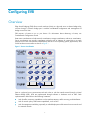
Overview
Edge Virtual Bridging (EVB) allows virtual machines (VMs) on a physical server to obtain bridge relay
services through a common bridge port. It enables coordinated configuration and management of
bridge services for VMs.
EVB requires a license to run on your device. For information about obtaining a license, see
Fundamentals Configuration Guide.
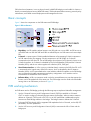
Data center virtualization includes network virtualization, storage virtualization, and server virtualization.
Server virtualization uses specific virtualization software such as VMware to create VMs on a single
physical server. Each VM operates independently and has its own operating system, applications, and
virtual hardware environments as shown in Figure 1.
Figure 1 Server virtualization
VMs on a physical server communicate with each other or with the outside network through a Virtual
Ethernet Bridge (VEB). VEBs are implemented through software or hardware such as NICs. Both
implementation methods have the following limitations:
• Lack of traffic monitoring capabilities such as packets statistics, traffic mirroring, and NetStream.
• Lack of network policy enforcement capabilities, such as QoS.
• Lack of management scalability, especially in unified deployment of the internal server network and
the external network.

2
EVB solves these limitations. It uses a physical switch (called EVB bridge) to switch traffic for VMs on a
directly connected physical server (called EVB station). EVB implements traffic monitoring, network policy
enforcement, and unified network deployment and management for VMs.
Basic concepts
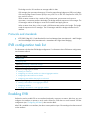
Figure 2 shows the components on the EVB station and EVB bridge.
Figure 2 EVB architecture
• Edge Relay—An ER transfers packets between one URP and one or more DRPs. An ER has one or
more DRPs and one URP. Both URP and DRPs are called ER ports. An EVB station can have multiple
ERs.
• S-channel—A point-to-point S-VLAN established between a Port-mapping S-VLAN component in
an EVB station and a Port-mapping S-VLAN component in an EVB bridge. An S-channel
corresponds to the URP of an ER. On an EVB bridge, the end point of an S-channel is known as an
S-channel interface. An S-channel is identified by the S-VLAN Identifier (SVID) and the S-channel
Identifier (SCID), and the two values together are called an (SCID, SVID) pair.
• Virtual Station Interface—A VSI is a port on a VM that directly connects to the DRP of an ER. A VSI
is associated with a logical entity called VSI instance, which is identified by the VSI Instance
Identifier (VSIID). A VSI is associated with a virtual interface called VSI interface on the EVB bridge
port to implement VM traffic management and policy configuration. A VSI interface can be
considered as a subinterface of an S-channel.
• Reflective Relay—A RR is an operation mode in which a received frame on a port that supports this
function can be forwarded out of the same port. The EVB bridge uses this mode to forward traffic
among VMs on an EVB station, as shown in Figure 2.
EVB working mechanism
An EVB station and an EVB bridge go through the following steps to implement VM traffic management:
1. Use the S-channel Discovery and Configuration Protocol (CDCP) to establish an S-channel.
CDCP is used to configure S-channels between stations and bridges. When a station creates or
deletes an S-channel, CDCP sends a CDCP TLV in an LLDP packet that is addressed using the
Nearest non-TPMR Bridge address to the bridge. The bridge creates or deletes the S-channel.
2. Exchange EVB TLVs through LLDP to negotiate EVB capabilities for the S-channel, such as RR, ECP
parameters, and VDP parameters.
3. Use the VSI Discovery and Configuration Protocol (VDP) to associate the VSIs of VMs with the
bridge port.

3
The bridge uses the VSI interfaces to manage traffic for VMs.
VDP manages the association between a VSI and a station-facing bridge port (SBP) on a bridge.
VDP uses the Edge Control Protocol (ECP) to carry VDP TLVs. A VDP TLV comprises the VSIID, VSI
type, and VSI version.
When a station creates a VM, it sends a VDP pre-associate, pre-associate with resource
reservation, or associate packet to the bridge. The bridge sends the request to a VSI manager. The
VSI manager notifies the bridge to create a VSI interface and apply policies.
When a station shuts down a VM, it sends a VDP de-associate packet to the bridge. The bridge
sends the request to the VSI manager. The VSI manager notifies the bridge to delete the VSI
interface.
Protocols and standards
• IEEE P802.1Qbg/D2.2, Draft Standard for Local and Metropolitan Area Networks—MAC Bridges
and Virtual Bridged Local Area Networks - Amendment XX: Edge Virtual Bridging
EVB configuration task list
This document only describes EVB bridge configuration. For information about EVB station configuration,
see the station manual.
Tasks at a
g
lance
Enabling EVB
Configuring LLDP
(Optional.) Specifying a default VSI manager
(Optional.) Configuring VDP negotiation parameters
(Optional.) Configuring an S-channel:
• Creating an S-channel
• Configuring an S-channel interface or S-channel aggregate interface
• Configuring the RR mode for an S-channel
• Configuring MAC address learning for an S-channel
(Optional.) Configuring a VSI interface or VSI aggregate interface:
• Creating a VSI interface or VSI aggregate interface
• Configuring VSI filters
• Activating a VSI interface or VSI aggregate interface
Enabling EVB
Perform this task to enable EVB on an interface that directly connects to a station. After that, you must
configure the interface to operate in trunk mode. Otherwise, EVB does not work because VSI filter
configuration (see "Configuring VSI filters") does not tak
e effect.
After EVB is enabled on an interface, the device cannot perform Layer 3 forwarding to the data received
on the interface.

4
A default S-channel is created on an interface after EVB is enabled on the interface. Both SCID and SVID
are 1. After an S-channel is created, an S-channel interface or S-channel aggregate interface is created
and operates in access mode.
Do not enable both EVB and VLAN mapping, both EVB and TRILL, or both EVB and QinQ on the same
interface.
Do not create a service instance for an interface enabled with EVB, and vice versa.
Do not assign interfaces enabled with EVB and not configured with the trill evb-support command to the
same VLAN as interfaces enabled with TRILL. For more information about TRILL, see TRILL Configuration
Guide. For more information about the trill evb-support command, see TRILL Command Reference.
To enable EVB:
Ste
p
Command
Remarks
1. Enter system view.
system-view
N/A
2. Enter Layer 2 Ethernet
interface view or Layer 2
aggregate interface view.
interface interface-type
interface-number
N/A
3. Enable EVB.
evb enable
By default, EVB is disabled on an
interface.
Configuring LLDP
EVB uses LLDP to transmit CDCP TLVs, and CDCP TLVs are carried by the LLDP packet that is addressed
using the Nearest non-TPMR Bridge address, so you must configure LLDP.
For detailed information about the lldp global enable, lldp enable and lldp agent nearest-nontpmr
admin-status commands, see Layer 2—LAN Switching Command Reference.
To configure LLDP:
Ste
p
Command
Remarks
1. Enter system view.
system-view
N/A
2. Enable LLDP globally.
lldp global enable
By default, LLDP is disabled
globally.
3. Enter Layer 2 Ethernet
interface view or Layer 2
aggregate interface view.
interface interface-type
interface-number
N/A
4. Enable LLDP on the interface
lldp enable
By default, LLDP is enabled on an
interface.
5. Configure the Nearest
non-TPMR Bridge agent for
LLDP to operate in TxRx mode.
lldp agent nearest-nontpmr
admin-status txrx
The default mode is disable.

5
Specifying a default VSI manager
When the bridge receives a VDP packet (except for a De-Associate packet) from a station, it contacts the
VSI manager specified in the VDP packet to get VSI interface resources and policies.
The VSI manager ID TLV in a VDP packet carries the VSI manager's IP address. If the value for the TLV is
0, the VDP packet does not contain a VSI manager's IP address, so the bridge communicates with the
specified default VSI manager.
To specify a default VSI manager:
Ste
p
Command
Remarks
1. Enter system view.
system-view
N/A
2. Specify a default VSI
manager.
evb default-manager { { ip
ip-address | ipv6 ipv6-address |
name name } [ port port-number ] |
local-server }
By default, no default VSI manager
is specified.
Configuring VDP negotiation parameters
After a station sends a VDP request other than a De-Associate request to the bridge, the bridge requests
the VSI interface resources and policies from the VSI manager. If the bridge receives no response from the
VSI manager before the VDP response-wait-delay time expires, the VDP negotiation fails. The VDP
response-wait-delay time on the EVB bridge is calculated as:
VDP response-wait-delay time (seconds) = 2
VDP
resource-wait-delay
× 10
—
5
.
The value of the VDP resource wait-delay exponent is the larger of the values proposed by the station and
bridge through EVB TLV.
When a Pre-Associate, Pre-Associate with Resource Reservation, or Associate request from a station is
successfully handled, the VSI manager notifies the bridge to create a VSI interface for the corresponding
VM. Then the bridge starts a "VDP keepalive timer" for the VSI interface. If the bridge receives no
keepalive from the station before the timer expires, it releases resources reserved for the association. The
VDP keepalive time is calculated as:
VDP keepalive time (seconds) = 1.5 × [ 2
VDP
keepalive
+ (2 × ECP maximum retransmission time + 1) × 2
ECP
retransmission
] × 10
—
5
.
The value assigned to the VDP keepalive exponent, the ECP maximum retransmission time, and the ECP
retransmission exponent are the larger of the values proposed for each by the station and bridge through
EVB TLV.
To configure VDP negotiation parameters:
Ste
p
Command
Remarks
1. Enter system view.
system-view
N/A
2. Enter Layer 2 Ethernet
interface view or Layer 2
aggregate interface view.
interface interface-type
interface-number
N/A

6
Ste
p
Command
Remarks
3. Configure the VDP
resource-wait-delay timer
exponent.
evb vdp timer resource-wait-delay
exponent value
The default is 20.
4. Configure the VDP keepalive
timer exponent.
evb vdp timer keepalive exponent
value
The default is 20.
Configuring an S-channel
Creating an S-channel
An S-channel is automatically created by CDCP, and the system automatically saves the configuration in
the configuration file on the bridge. You can also manually create an S-channel by performing this task.
If an (SCID, SVID) pair for an S-channel is created both automatically and manually, the one
automatically created takes precedence.
After an S-channel is created, an S-channel interface or S-channel aggregate interface is generated.
Removing an S-channel also removes the S-channel interface or S-channel aggregate interface. A
manually created S-channel interface or S-channel aggregate interface operates in access mode. An
S-channel interface or S-channel aggregate interface that is automatically created through CDCP
operates in trunk mode.
An S-channel interface is associated with the S-channel that is created on a Layer 2 Ethernet interface. An
S-channel aggregate interface is associated with the S-channel that is created on a Layer 2 aggregate
interface.
The device checks C-VLAN tagged frames (frames taking the original VLAN tags) entering an S-channel
for their C-VLAN tags. If the C-VLAN does not belong to the VLANs that the S-channel and the port where
the S-channel is created permit, the device cannot transmit the frames. Therefore, you must specify the
C-VLAN range for the frames that an S-channel can transmit before you assign the S-channel and the port
where the S-channel is created to these C-VLANs. For more information about assigning ports to a VLAN,
see Layer 2—LAN Switching Configuration Guide.
When you create an S-channel, follow these guidelines:
• Create an S-channel on an interface with EVB enabled. Otherwise, an error message appears.
• After EVB is enabled on an interface, a default S-channel (with both SCID and SVID as 1) is
automatically created.
• When you manually create an S-channel, do not use the SCID or SVID being used by any other
S-channel.
• To manually create or remove S-channel, disable CDCP that automatically performs these
operations.
To create an S-channel:
Ste
p
Command
Remarks
1. Enter system view.
system-view
N/A
2. Enter Layer 2 Ethernet
interface view or Layer 2
aggregate interface view.
interface interface-type
interface-number
N/A

7
Ste
p
Command
Remarks
3. Create an S-channel.
evb s-channel channel-id
service-vlan svlan-id
By default, only an automatically
created default S-channel (with
both SCID and SVID as 1) exists on
an interface with EVB enabled.
Configuring an S-channel interface or S-channel aggregate
interface
Ste
p
Command
Remarks
1. Enter system view.
system-view
N/A
2. Enter S-channel interface or
S-channel aggregate
interface view.
interface { s-channel |
schannel-aggregation }
interface-number:channel-id
N/A
3. (Optional.) Configure the
expected bandwidth of the
interface.
bandwidth bandwidth-value
By default, the expected
bandwidth of an S-channel
interface or S-channel aggregate
interface is the default maximum
bandwidth of the physical port to
which the interface belongs.
4. (Optional.) Restore the default
settings for the interface.
default N/A
5. (Optional.) Configure a
description for the interface.
description text
The default description information
is "interface name Interface."
6. Bring up the interface.
undo shutdown
By default, the S-channel interface
or S-channel aggregate interface is
up.
Configuring the RR mode for an S-channel
EVB TLVs exchanged through LLDP allow an EVB station and EVB bridge to negotiate the use of reflective
relay. When the EVB station requests the use of the RR mode and the EVB bridge supports the RR mode,
the bridge performs the following tasks:
• Automatically enables the RR mode for the S-channel.
• Saves the configuration in the configuration file on the bridge.
You can also manually enable the RR mode for an S-channel by performing this task.
To configure the RR mode for an S-channel:
Ste
p
Command
Remarks
1. Enter system view.
system-view
N/A
2. Enter S-channel interface
view or S-channel aggregate
interface view.
interface { s-channel |
schannel-aggregation }
interface-number:channel-id
N/A

8
Ste
p
Command
Remarks
3. Enable the RR mode for the
S-channel.
evb reflective-relay
By default, the RR mode is
disabled for an S-channel.
Configuring MAC address learning for an S-channel
You can manually disable the MAC address learning function for an S-channel by performing this task.
To disable MAC address learning for an S-channel:
Ste
p
Command
Remarks
1. Enter system view.
system-view
N/A
2. Enter S-channel interface
view or S-channel aggregate
interface view.
interface { s-channel |
schannel-aggregation }
interface-number:channel-id
N/A
3. Disable MAC address
learning for the S-channel.
evb mac-learning forbidden
By default, the MAC address
learning function is enabled for an
S-channel.
IMPORTANT:
• For an S-channel with the RR
mode disabled, do not disable
its MAC address learning
function. Otherwise, the
bridge might fail to forward
traffic for VMs on the EVB
station.
• After you disable the MAC
address learning function for
an S-channel, the bridge will
discard packets with an
unknown source MAC
address.
Configuring a VSI interface or VSI aggregate
interface
Creating a VSI interface or VSI aggregate interface
A VSI interface is created on an S-channel interface through this task, and it is a subinterface of the
S-channel interface. A VSI aggregate interface is created on an S-channel aggregate interface, and it is
a subinterface of the S-channel aggregate interface. Removing an S-channel also removes all its VSI
interfaces and VSI aggregate interfaces.

9
VSI interfaces or VSI aggregate interfaces are typically created by a VSI manager. You can create a VSI
interface or VSI aggregate interface, or modify its Pre-Associate and Associate properties through this
task.
To create a VSI interface or VSI aggregate interface:
Ste
p
Command
Remarks
1. Enter system view.
system-view
N/A
2. Enter S-channel interface
view or S-channel aggregate
interface view.
interface { s-channel |
schannel-aggregation }
interface-number:channel-id
N/A
3. Create a VSI interface or VSI
aggregate interface.
evb vsi vsi-local-id { association |
pre-association }
By default, no VSI interface or VSI
aggregate interface exists on an
S-channel.
Configuring VSI filters
The EVB bridge uses a VSI filter to identify VSI traffic for a VM. Filters are usually assigned by a VSI
manager. You can manually create or remove VSI filters through this task.
A VSI filter contains a set of VID values, MAC addresses, and group ID values. EVB supports the
following filter info formats:
• VLAN ID
• VLAN ID + MAC
• Group ID + VLAN ID
• Group ID + VLAN ID + MAC
When you configure VSI filters on a VSI interface, follow these guidelines:
• Before you configure a VSI filter on a VSI interface, make sure the S-channel interface to which the
VSI interface belongs operates in trunk mode. Otherwise, the VSI filter configuration fails.
• After you configure a VSI filter on a VSI interface, an S-channel interface automatically permits the
VLAN that is configured in the VSI filter for the subordinate VSI interface. The same rule takes effect
on Layer 2 interfaces associated with S-channels.
• When you delete a VSI filter that contains information about a VLAN on a VSI interface, the other
VSI filters on all VSI interfaces of an S-channel interface might not contain the VLAN. If they do not,
the S-channel interface automatically denies traffic from the VLAN that is configured on the VSI filter.
The same rule takes effect on Layer 2 interfaces associated with S-channels.
• When a filter configured on a VSI contains information about a VLAN, you must not configure the
filter on the same VSI interface again or on other VSI interfaces of the S-channel interface. If you do,
an error message appears.
• If the VSI filter is a set of VID values, and the MAC address learning function for the corresponding
S-channel is disabled, traffic for the VSI cannot be forwarded.
• Activate a VSI interface after configuring a VSI filter, and deactivate a VSI interface before removing
a VSI filter.
When you configure VSI filters on a VSI aggregate interface, follow these guidelines:

10
• Before you configure a VSI filter on a VSI aggregate interface, make sure the S-channel aggregate
interface to which the VSI aggregate interface belongs operates in trunk mode. Otherwise, the VSI
filter configuration fails.
• After you configure a VSI filter on a VSI aggregate interface, an S-channel aggregate interface
automatically permits the VLAN that is configured in the VSI filter for the subordinate VSI aggregate
interface. The same rule takes effect on Layer 2 aggregate interfaces associated with S-channels.
• When you delete a VSI filter that contains information about a VLAN on a VSI aggregate interface,
the other VSI filters on all VSI aggregate interfaces of an S-channel aggregate interface might not
contain the VLAN. If they do not, the S-channel aggregate interface automatically denies traffic
from the VLAN that is configured on the VSI filter. The same rule takes effect on Layer 2 aggregate
interfaces associated with S-channels.
• When a filter configured on a VSI aggregate interface contains information about a VLAN, you
must not configure the filter on the same VSI aggregate interface again or on other VSI aggregate
interfaces of the S-channel aggregate interface. If you do, an error message appears.
• Activate a VSI aggregate interface after configuring a VSI filter, and deactivate a VSI aggregate
interface before removing a VSI filter.
To configure a VSI filter:
Ste
p
Command
Remarks
1. Enter system view.
system-view
N/A
2. Enter VSI interface view or VSI
aggregate interface view.
interface { s-channel |
schannel-aggregation }
interface-number:channel-id.vsi-loc
al-id
N/A
3. Configure a VSI filter.
evb vsi filter [ group group-id ] vlan
vlan-id [ mac mac-address ]
By default, no VSI filter is
configured.
Activating a VSI interface or VSI aggregate interface
Configurations such as traffic monitoring (see ACL and QoS Configuration Guide) on a VSI interface or
VSI aggregate interface take effect only after the VSI interface or VSI aggregate interface is activated.
When a VSI interface or VSI aggregate interface is not activated, only configure filters on the VSI
interface or VSI aggregate interface.
Activate a VSI interface or VSI aggregate interface after configuring a VSI filter, and deactivate a VSI
interface or VSI aggregate interface before removing a VSI filter.
To activate a VSI interface or VSI aggregate interface:
Ste
p
Command
Remarks
1. Enter system view.
system-view
N/A
2. Enter VSI interface view
or VSI aggregate
interface view.
interface { s-channel |
schannel-aggregation }
interface-number:channel-id.vsi-lo
cal-id
N/A

11
Ste
p
Command
Remarks
3. (Optional.) Configure
the expected bandwidth
of the VSI interface or
VSI aggregate interface.
bandwidth bandwidth-value
By default, the expected bandwidth of a
VSI interface or VSI aggregate interface
is the default maximum bandwidth of the
physical port to which the VSI interface
or VSI aggregate interface belongs.
4. (Optional.) Restore the
default settings for the
VSI interface or VSI
aggregate interface.
default N/A
5. (Optional.) Configure a
description for the VSI
interface or VSI
aggregate interface.
description text
The default description information is
"interface name Interface."
6. Activate the VSI interface
or VSI aggregate
interface.
evb vsi active
By default, no VSI interface or VSI
aggregate interface is activated.
Displaying and maintaining EVB
Execute display commands in any view and the reset command in user view.
Task Command
Display CDCP negotiation
information.
display evb cdcp [ interface interface-type interface-number ]
Display S-channel EVB TLV
negotiation information.
display evb evb-tlv [ interface interface-type { interface-number |
interface-number:channel-id } ]
Display S-channel information. display evb s-channel [ interface interface-type interface-number ]
Display EVB summary. display evb summary
Display VSI interface information.
display evb vsi [ verbose ] [ interface interface-type { interface-number
| interface-number:channel-id |
interface-number:channel-id.vsi-local-id } ]
Display information about an
S-channel interface, S-channel
aggregate interface, VSI interface, or
a VSI aggregate interface.
• display interface [ s-channel | schannel-aggregation ] [ brief
[ down ] ]
• display interface [ { s-channel | schannel-aggregation }
[ interface-number:channel-id |
interface-number:channel-id.vsi-local-id ] ] [ brief [ description ] ]
Clear statistics for an S-channel
interface, S-channel aggregate
interface, VSI interface, or a VSI
aggregate interface.
reset counters interface [ { s-channel | schannel-aggregation }
[ interface-number:channel-id |
interface-number:channel-id.vsi-local-id ] ]

12
EVB configuration example
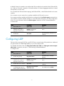
Network requirements
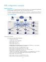
As shown in Figure 3, the Layer 2 network of a data center comprises two switches that form an IRF fabric,
four EVB bridges, and four EVB stations. They communicate within VLAN 100.
Create VM 1 with a MAC address of 0050-5684-21C7 on EVB station 1, and set VM1 as the FTP server
with a CIR of 2048 kbps and a PIR of 4096 kbps. Only the R&D center is allowed to access the network.
Figure 3 Network diagram
Configuration procedure
This section only contains EVB configurations.
1. Configure the EVB bridge:
# Create VLAN 100 on EVB bridge 1.
<EVB_bridge1> system-view
[EVB_bridge1] vlan 100
[EVB_bridge1-vlan100] quit
# Enable EVB on Ten-GigabitEthernet 1/0/1 that connects to EVB station 1, and configure
Ten-GigabitEthernet 1/0/1 to operate in trunk mode.
[EVB_bridge1] interface ten-gigabitethernet 1/0/1
[EVB_bridge1-Ten-GigabitEthernet1/0/1] evb enable
[EVB_bridge1-Ten-GigabitEthernet1/0/1] port link-type trunk
[EVB_bridge1-Ten-GigabitEthernet1/0/1] quit
# Enable LLDP on EVB bridge 1 globally. Enable LLDP on Ten-GigabitEthernet 1/0/1, and
configure the Nearest non-TPMR Bridge agent for LLDP to operate in TxRx mode.
[EVB_bridge1] lldp global enable
[EVB_bridge1] interface ten-gigabitethernet 1/0/1
[EVB_bridge1-Ten-GigabitEthernet1/0/1] lldp enable

13
[EVB_bridge1-Ten-GigabitEthernet1/0/1] lldp agent nearest-nontpmr admin-status txrx
[EVB_bridge1-Ten-GigabitEthernet1/0/1] quit
# Specify the IP address and port number for the default VSI manager on EVB bridge 1.
[EVB_bridge1] evb default-manager ip 192.168.1.1 port 8080
Configure other EVB bridges in the same way. (Details not shown.)
2. Configure the EVB station:
Configure the EVB station on the VMM. For more information about configuring VMs through the
VMM, see the VMM manual. (Details are not shown.)
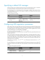
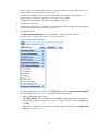
3. Configure the NMS:
Use VAN Connection Manager of IMC on the NMS to configure network resources.
The IMC VCM 5.2 (E0401L01) version is used in this section.
Figure 4 VAN Connection Manager
To configure the NMS, log in to IMC, click the Resource tab, and select VAN Connection Manager
from the navigation tree (see Figure 4), and perform the following steps:
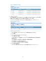
a. Add an EVB
bridge (Edge Switch):
Select Edge Switch from the navigation tree, click Add on the page that appears, select the four
devices in the IP address range of 192.168.1.11 through 192.168.1.14 from IP View, and
click OK.
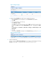
EVB bridge 1, EVB bridge 2, EVB bridge 3, and EVB bridge 4 are displayed in the Edge Switch
List page, as shown in Figure 5.
Page is loading ...
Page is loading ...
Page is loading ...
Page is loading ...
Page is loading ...
-
 1
1
-
 2
2
-
 3
3
-
 4
4
-
 5
5
-
 6
6
-
 7
7
-
 8
8
-
 9
9
-
 10
10
-
 11
11
-
 12
12
-
 13
13
-
 14
14
-
 15
15
-
 16
16
-
 17
17
-
 18
18
-
 19
19
-
 20
20
-
 21
21
-
 22
22
-
 23
23
-
 24
24
-
 25
25


H3C S6300 Series Evb Configuration Manual
- Category
- Software
- Type
- Evb Configuration Manual
- This manual is also suitable for
Ask a question and I''ll find the answer in the document
Finding information in a document is now easier with AI
Related papers
-
H3C S10500 Series Configuration manual
-
-
-
-
-
-
H3C S3100 Series Installation guide
-
H3C SR6600 SPE-FWM Configuration manual
-
H3C H3C S7500E-X Configuration manual
-
Other documents
-
Aruba JH395A Configuration Guide
-
Aruba JH691A Reference guide
-
AVE Parallel Device with DB-25 Connectors P-2-RS User manual
-
Aruba JH691A Configuration Guide
-
Lenovo Flex System Fabric CN4093 Application Manual
-
-
-
Lenovo RackSwitch G8264 Command Reference Manual
-
-