Milwaukee 48-22-8558 Operating instructions

Type
Operating instructions

This manual is also suitable for

Cat. No. / No de cat.
48-22-8556, 48-22-8557, 48-22-8558
OPERATOR'S MANUAL
MANUEL de L'UTILISATEUR
MANUAL del OPERADOR
WARNING To reduce the risk of injury, user must read and understand operator's manual.
AVERTISSEMENT An de réduire le risque de blessures, l'utilisateur doit lire et bien
comprendre le manuel.
ADVERTENCIA Para reducir el riesgo de lesiones, el usuario debe leer y entender el manual.
Este manual se aplica a los modelos anteriores (puede venderse por separado)
56" HIGH CAPACITY STEEL STORAGE CHEST &
56" HIGH CAPACITY STEEL STORAGE CABINET
COFFRE DE RANGEMENT EN ACIER GRANDE CAPACITÉ DE
1,42 M (56") ET CABINET DE RANGEMENT EN ACIER GRANDE
CAPACITÉ DE 1,42 M (56")
CAJA DE ALMACENAMIENTO DE ACERO DE GRAN CAPACIDAD
DE 1,42 M (56") Y GABINETE DE ALMACENAMIENTO DE ACERO
DE GRAN CAPACIDAD DE 1,42 M (56")
2
3
IMPORTANT SAFETY INSRUCTIONS
WARNING
READ ALL SAFETY WARNINGS
AND ALL INSTRUCTIONS. Failure
to follow the warnings and instructions may re-
sult in serious injury. Save all warnings and in-
structions for future reference.
WORK AREA SAFETY
Use the chest/cabinet and accessories in ac-
cordance with these instructions and in the
manner intended, taking into account the working
conditions. Use of the chest/cabinet for operations
different from those intended could result in a haz-
ardous situation.
Keep work area clean and well lit. Cluttered or
dark areas invite accidents.
Fully assemble the chest/cabinet according to the
assembly instructions. Do not leave off any pieces.
Chest must be fastened by screws through
connectors after it has been placed on top of
cabinet.
Do not modify the chest/cabinet in any way. Use
only specically recommended accessories. Drilling
holes or modifying the chest/cabinet will lower the
load capacity, which can cause the chest/cabinet to
collapse, resulting in injury.
Lock wheels when chest/cabinet is not being
moved. Unlocked wheels can allow the chest/
cabinet to move unexpectedly.
•Keep the chest/cabinet on a level surface. Do not
load, unload, or park chest/cabinet on an incline.
The chest/cabinet may become unbalanced and tip,
resulting in injury.
Always balance the chest/cabinet load to avoid
tipping. Unbalanced chests/cabinets are more likely
to tip when being moved or when using the chest/
cabinet work surfaces. Evenly distribute the weight
front to back and side to side. Place more than half
the total load weight on the bottom cabinet when pos-
sible. To help prevent the chest/cabinet from tipping,
load the product starting with the bottom drawers.
Do not exceed the maximum product weight,
including contents. Do not exceed the maximum
weight for each drawer. Overloaded chests/
cabinets can tip, collapse, or damage drawer slides.
Do not open more than one drawer at a time.
Chest/cabinet may tip, causing injury.
Keep children and bystanders away while
loading, unloading, and moving chest/cabinet.
Distractions can cause you to lose control.
Only lift the chest/cabinet according to the in-
structions in this manual. Other methods may be
dangerous, resulting in injury.
Only transport the chest/cabinet when empty.
Properly secure when transporting.
Do not mount the chest/cabinet on a truck bed
or any other moving object.
Lock both the lid and all drawers before rolling
the chest/cabinet. The drawers could come open
and make the chest/cabinet unstable and tip.
Only roll the chest/cabinet short distances by
using the handle provided.
Secure all items before rolling the chest/cabinet.
Loose items could shift, causing the chest/cabinet
to become unstable.
Do not use drawers as steps. Do not stand on the
chest/cabinet. Chest/cabinet will tip, causing injury.
Be careful when closing the chest top cover.
Remove hands before closing the top cover.
Do not use chest/cabinet in explosive atmo-
spheres, such as in the presence of ammable
liquids, gases or dust. This equipment has internal
arcing or sparking parts. Chest/cabinet should not
be located in a recessed area or below oor level.
Chest/cabinet plugs must match the outlet.
Never modify the plug in any way. Do not use
any adapter plugs with earth (grounded) chest/
cabinet power strips. Unmodied plugs and match-
ing outlets will reduce risk of electric shock.
Avoid body contact with earthed or grounded
surfaces such as pipes, radiators, ranges and
refrigerators. There is an increased risk of electric
shock if your body is earthed or grounded.
Maintain chest/cabinet. Check for misalignment
or binding wheels, breakage or bending of drawer
slides or other parts and any other condition that
may affect the chest/cabinet's operation. Do not use
damaged chest/cabinet.
Maintain labels and nameplates. These carry
important information. If unreadable or missing,
contact a MILWAUKEE service facility for a free
replacement.
Have your chest/cabinet serviced by a qualied
repair person using only identical replacement
parts. Visit a local authorized service center for
repairs. Components, such as the power strip, are
not user replaceable. This will ensure that the safety
of the chest/cabinet is maintained.
WARNING
Chemical Burn Hazard.
This device contains a
lithium button/coin cell battery. A new
or used battery can cause severe
internal burns and lead to death in as
little as 2 hours if swallowed or enters the body.
Always secure the battery cover. If it does not
close securely, stop using the device, remove
the batteries, and keep it away from children. If
you think batteries may have been swallowed
or entered the body, seek immediate medical
attention.
SYMBOLOGY
Warning
Read Operator's Manual
Electrical Shock Hazard
Do not open more than one drawer at a
time. Chest/cabinet may tip, causing injury.
Be careful when closing the chest top
cover. Remove hands before closing
the cover.
Chest must be fastened by screws
through connectors after it has been
placed on top of cabinet.
Lock wheels when chest/cabinet is not
being moved. Unlocked wheels can
allow the chest/cabinet to move
unexpectedly.
Do not use drawers as steps. Chest/
cabinet may tip, causing injury.
FPO
Lock both the lid and all drawers before
moving the chest/cabinet.
SPECIFICATIONS
Two-slide drawer capacity ...........150 lbs. (68.0 kg)
Four-slide drawer capacity ........300 lbs. (136.0 kg)
Total capacity ......................... 3000 lbs. (1360.8 kg)
AC input volts ....................................................120
Hertz ....................................................................60
Watts ...............................................................1875
Max operating temperature .............221
°F
(105
°C)
FUNCTIONAL DESCRIPTION
1
15
4
14
9
6
1. Top chest
2. Utility hook
3. Chest mat
4. Tool hanger
5. Cabinet mat
6. Bottle opener
7. Cabinet corner
extrusion
8. Digital lock*
9. Front bumper
10. Rigid caster
11. Rolling cabinet
12. Tool organizer
13. Drawer slide
14. Swivel caster
with brake
15. Shelf hinge bracket
16. Storage shelf
2
3
20
5
23
8
27
17. Rear bumper
18. Charger mounts
19. Power strip
(14 AWG, 1.8 m)
20. Cord storage
bracket
21. Side handle
22.Grommet
23. Bracket
24. Paper towel holder
bracket
25. Paper towel holder
rod
26. Chest corner
extrusion
27. Gas lift strut
10
18
16
13
19
21
24
25
17
7
26
12
*See digital lock user manual for assembly and
operation instructions.
22
11
4
5
Hardware Included
NOTE: Items not shown in actual size. Hardware
lengths are approximate.
Hardware Item Description Quantity
AA
Bolt M6 x 16L 10
BB
Steel washer
19 x 8.5 x 2
16
CC
Bolt M8 x 12L 16
DD
Screw M4 x 12L 20
EE
Screw M6 x 12L 8
FF
Screw M4 x 16L 20
GG
Nut M6 2
HH
Shoulder bolt
M6 x 8L
2
II
Nylon washer
19 x 8.5 x 1.5
2
JJ Screw M6 x 16L 2
Item Description Quantity
Side handle 1
Tool hanger 1
6" Swivel caster
with brake
2
6" Rigid caster 2
Bracket 2
Shelf hinge bracket 2
Front bumper 8
Rear bumper 2
Chest corner extrusion 2
Cabinet corner extrusion 2
Cord storage bracket 4
Utility hook 2
Paper towel
holder bracket
2
Paper towel holder rod 1
Bottle opener 1
NOTE:
intended location of your chest/cabinet. This product
Attaching the Side Handle
Attach the side handle to the rolling cabinet using
four bolts (AA). The side handle can be attached to
either side of the rolling cabinet.
NOTE: The holes in the cabinet are tapped and do
not require nuts.
AA
Installing the Casters
CAUTION
Two people may be required to
complete installation.
Do not overtighten the screws.
1. Ensure all cabinet drawers are securely locked into
place using the key lock on the rolling cabinet.
2. Lay the rolling cabinet on its back. Use the packag-
3. Mount the two swivel casters with brake to the
rolling cabinet using four bolts (CC) and washers
ekarb htiw sretsac leviws ehT .retsac rep )BB(
should be installed on the end of the cabinet with
the side handle.
4. Mount the two rigid casters to the opposite end
of the rolling cabinet using four bolts (CC) and
washers (BB) per caster.
5. Tighten all bolts securely with a wrench.
GROUNDING
WARNING
Improperly connecting the ground-
ing wire can result in the risk of
if you are in doubt as to whether the outlet is
properly grounded. Do not modify the plug pro-
vided with the chest/cabinet. Never remove the
grounding prong from the plug. Do not use the
chest/cabinet if the cord or plug is damaged. If
damaged, have it repaired before use. If the plug
Chests/Cabinets with Three Prong Plugs
Chests/cabinets marked Grounding Required
have a power strip with a three wire cord and three
prong grounding plug. The plug must be connected
to a properly grounded outlet (See Figure A). If the
power strip should electrically malfunction or break
down, grounding provides a low resistance path to
carry electricity away from the user, reducing the risk
of electric shock.
The grounding prong in the plug is connected through
the green wire inside the cord to the grounding sys-
tem in the power strip. The green wire in the cord
must be the only wire connected to the power strip's
grounding system and must never be attached to an
electrically “live” terminal.
Your power strip must be plugged into
Fig. A
an appropriate outlet, properly in-
stalled and grounded in accordance
with all codes and ordinances. The
plug and outlet should look like those
in Figure A.
ASSEMBLY
CAUTION
Be sure to follow the assembly in-
structions for the appropriate
chest/cabinet. Do not use power tools to as-
semble chest/cabinet. Tighten bolts with hand
wrenches.
Tools Required (Not Included)
Phillips
screwdriver
Safety
goggles
10 mm
Wrench
13 mm
Wrench
6. Return the rolling cabinet to its upright position.
BB
CC
Installing the Chest onto the Cabinet
CAUTION
Two people may be required to
complete installation.
1. Place the top chest on top of the rolling cabinet.
NOTE: The holes in the cabinet are tapped and do
not require nuts.
2. Attach the two brackets to the back of the product
to secure the top chest to the rolling cabinet. Place
the brackets over the holes and secure with four
screws (DD) per bracket.
3. Tighten all screws securely with a Phillips screw-
driver.
DD
Installing the Drawer Liners and Mat
Place the drawer liners in appropriately sized draw-
ers and the mat in the chest lid area to protect the
surface.
6
7
Installing the Corner Extrusions
and Bumpers
Place the front bumpers on both ends of the extrusion
by sliding the extrusion into the cavity of the bumpers.
Attach the front bumpers with extrusions using two
screws (FF) per bumper.
Attach the two rear bumpers to the back of the lower
cabinet using two screws (FF) per bumper.
FF
Installing the Cord Storage Brackets
Attach the brackets to the back of the chest and
cabinet with two screws (DD) per bracket. Orient the
brackets with one pointed up and one pointed down
so that the power outlet cord can be wrapped around
the brackets for storage.
Installing the Storage Shelf
Attach the shelf hinge brackets to the right cabinet
using two bolts (AA) for each bracket. Attach the
storage shelf to the brackets using one washer (II),
nut (GG) and bolt (HH) on each end.
GG
AA
HH
II
Installing the Tool Hanger
Attach the tool hanger to the left end of the chest
using two bolts (AA).
Installing the Utility Hooks and
Paper Towel Holder
Attach the utility hooks and paper towel holder to
either end of the chest using two screws (EE) for
each hook and bracket.
Installing the Bottle Opener
Attach the bottle opener to the left side of the cabinet
using two screws (JJ).
Installing the Power Cord
Locate the power cord inside one of the right-hand
drawers. Untie the power cord and gently pull the
cord plug through the grommet.
OPERATION
WARNING
To avoid injury or property damage,
do not exceed maximum shelf ca-
pacity. Use care when moving chest/cabinet on
incline or rough surface. Chest/cabinet may tip
if weight is not evenly distributed front to back
and side to side. Place more than half the total
load weight on the bottom cabinet when possible.
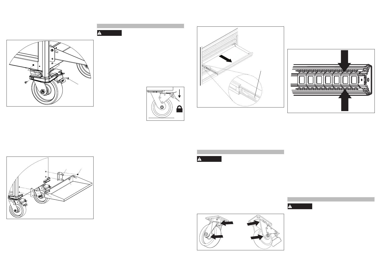
Locking and Unlocking the Chest/Cabinet
NOTE: The drawers must be fully closed before
locking/unlocking the unit.
Insert the key. Turn it fully left to lock, or fully right
to unlock. Always remove the key after locking and
unlocking.
Using the Caster Brakes
To lock the swivel casters, step
down on the levers marked
ON. Be sure to lock both
casters to prevent chest/
cabinet from rolling or swiv-
eling. To unlock casters,
push down on the levers
marked OFF.
Moving the Chest/Cabinet on
an Incline or Rough Surface
Take care that the chest/cabinet does not tip or
become unbalanced when moving it on an incline
or rough surface. Do not exceed an incline of 10
degrees. Lock the chest/cabinet and secure all items
before moving.
Rolling the Chest/Cabinet
The chest/cabinet is only intended for rolling short
distances. Only roll the chest/cabinet using the han-
dle. Do not push or pull chest/cabinet by the frame
or product may tip. Do not modify the chest/cabinet
in any way. Drilling holes or modifying the chest/
cabinet will lower the load capacity, which can cause
the chest/cabinet to collapse, resulting in injury. Lock
the chest/cabinet and secure all items before rolling.
Lifting the Chest/Cabinet
The cabinet and chest/cabinet combo are not
intended to be lifted. However, if you need to lift,
empty the chest/cabinet and then place straps or
forks inside and next to casters. Do not lift loaded
chests/cabinets. Be sure all bystanders are moved
away before lifting chest/cabinet.
Mounting Chargers
The rolling cabinet comes equipped with four pre-
installed charger mounting bosses, located below the
power strip. The charger mounts are suitable for hold-
ing MILWAUKEE M18™ & M12™ Multi Voltage char-
gers as well as M18™ chargers. To mount a charger,
install a screw (DD) into each boss, then slide the
charger's key-hole slots over the screws. Slide the
charger toward the oor to lock it onto the screws.
Removing the Drawers
1. Fully extend and empty the drawer.
2. Depending on the side, either lift or lower the
release lever on both sides so the slides can ride
over the stops. Pull out to remove.
Release Lever
Installing the Drawers
1. Pull the slides and slide carrier out until fully ex-
tended.
2. Hold the slide on the cabinet while aligning it with
the slide on the drawer.
3. Slightly insert one side and repeat for the other
side.
4. Slowly push the drawer until it is fully closed to
engage the slide.
5. Open and close the drawer to verify proper operation.
MAINTENANCE
WARNING
To reduce the risk of injury, contact
MILWAUKEE Corporate After Sales
Service Technical Support for ALL repairs and
replacement parts.
Maintaining the Chest/Cabinet
Keep your chest/cabinet in good repair by adopting a
regular maintenance program. Before use, examine
the general condition of your chest/cabinet. Check for
loose screws, misalignment, binding of wheels, bro-
ken parts and any other condition that may affect its
safe operation. Do not use a damaged chest/cabinet.
Maintaining the Casters
Grease the casters annually using high quality bear-
ing grease.
Grease
Points
Maintaining the Drawers
1. Periodically clean the drawers with a mild deter-
gent and water.
2. Remove grease and oil in drawer with a standard,
nonammable cleaning uid.
3. The use of drawer liners is recommended to
protect the nish inside the drawers and make
the drawers easier to clean. Drawer liners can be
cleaned with soap and water.
4. Lubricate the slides semi-annually with general
purpose grease or equivalent.
Grease
Points
Cleaning
This steel product has been coated with industrial
powder coating for a durable nish. To help protect
the powder coated nish, do not allow harsh chemi-
cals (oil, grease or other chemical) to remain on the
powder coating surface. Use a glass cleaner to
clean and maintain all surfaces of powder coating.
Keep the chest/cabinet handles and wheels clean,
dry and free of oil or grease. Use only mild soap
and a damp cloth to clean your chest/cabinet since
certain cleaning agents and solvents are harm-
ful to plastics. Some of these include: gasoline,
turpentine, lacquer thinner, chlorinated cleaning
solvents, ammonia and household detergents
containing ammonia. Never use flammable or
combustible solvents around chests/cabinets.
Service
For service and repair information, including the or-
dering of service parts, call our Corporate After Sales
Service Technical Support line at 1-800-SAWDUST,
or visit our website at www.milwaukeetool.com.
ACCESSORIES
WARNING
Modifying the chest/cabinet to ac-
cept other accessories may be
hazardous, resulting in injury or property dam-
age. Use only specically recommended acces-
sories according to the manufacturer's instruc-
tions.
For a complete listing of accessories, go online to
www.milwaukeetool.com or contact a distributor.
  • Page 1 1
  • Page 2 2
  • Page 3 3
  • Page 4 4
  • Page 5 5
  • Page 6 6
  • Page 7 7
  • Page 8 8
  • Page 9 9
  • Page 10 10
  • Page 11 11

Milwaukee 48-22-8558 Operating instructions

Type
Operating instructions
This manual is also suitable for

Ask a question and I''ll find the answer in the document

Finding information in a document is now easier with AI