IMPORTANT SAFETY INSTRUCTIONS
LIGHTED BULB IS HOT!
WARNING: To reduce the risk of FIRE or INJURY TO PERSON:
• Turn off and allow to cool before replacing bulb.
• Bulb gets HOT QUICKLY! Contact switch only when turning off.
• DO NOT remain in light if skin feels warm. (Light is intense, may cause "sunburn")
• DO NOT look directly at lighted bulb.
• Keep materials away from bulb that may burn.
• Use ONLY with wattage specified or lower.
• DO NOT touch bulb at any time, use a soft cloth. Oil from skin may damage bulb.
• DO NOT operate fixture with missing or damaged glass.
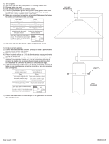
1) Thread cable through one hole in support rod. Cable should be flush with bottom
of hole in support rod.
2) Secure cable in place using provided allen wrench.
3) Pull cable towards top of center column and lay in channel of the appropriate disc.
4) Pull cable down towards support rod on opposite side of fixture from support rod
in step one.
5) Thread cable through hole in support rod and pull until cable is taunt. Secure in
place with allen wrench.
6) Repeat steps 1-5 for remaining cables.
7) Cut off excess cable flush with bottom of hole in support rod.
8) Turn off power.
9) Determine the height from ceiling you would like your fixture to hang. Fixture is provided
with (3) 11-1/2” long tubes that can be used or omitted to achieve desired height.
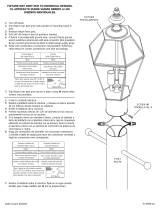
10) Assemble stem to fixture - First read and understand directions on Loctite®
marked on illustration.
NOTE: Loctite® must be applied to all stem threads as noted to prevent accidental
rotation of fixture during cleaning, relamping, etc. ...
11) Install canopy mounting screws, finger tight.
12) Loctite® threaded pipe from parts bag approximately 1/2” into stem.
13) Slip canopy then mounting strap over stem(s) assembled to fixture.
14) Loctite® ball swivel in place by threading a hexnut onto threaded pipe inside ball.
15) Lift mounting strap up against ball swivel, aligning slot in ball with tab in strap. Snap
ball retainer into place. Placing one side of ball retainer in place and then snapping
the other in is suggested.
16) Attach assembled fixture/mounting strap to outlet box. If ceiling is sloped assemble
mounting strap to ceiling with ball slot and tab towards lower portion of slope in
ceiling.
17) Attach ground wire from outlet box between cupped washer and green ground
screw and thread ground screw into mounting strap. If fixture is provided with ground
wire, connect fixture ground wire to outlet box ground wire with wire connectors
(not provided). Never connect ground wire to black or white power supply wire.
18) Make wire connections (connectors not provided.) Reference chart below for correct
connections and wire accordingly.
19) Carefully slip canopy up stem and secure to ceiling using lockwashers and ball
knobs.
20) Slip trim ring over socket cup and screw thumbscrews into holes in socket cup.
21) Insert recommended bulb. CAUTION: DO NOT touch bulb with bare hands. If this
happens, clean bulb with denatured alcohol and a lint free cloth.
22) Carefully slip glass over bulb and secure in place with thumbscrews. (DO NOT
over tighten.)
INSTRUCCIONES IMPORTANTES DE SEGURIDAD
LA BOMBILLA ENCENDIDA ES CALIENTE
ADVERTENCIA: Para disminuir el riesgo de INCENDIO o LESIONES ALAS PERSONAS:
• Apague y deje que se enfríe antes de cambiar la bombilla.
• La bombilla SE CALIENTA RÁPIDAMENTE. Use el interruptor sólo para apagar.
• NO permanezca en la luz si siente la piel caliente. (La luz es intensa y puede causar
"quemaduras").
• NO mire directamente a la bombilla.
• Mantenga alejados de la bombilla los artículos que puedan quemarse.
• Use SOLAMENTE con el vatiaje especificado o mas bajo.
• NO toque la bombilla en ningún momento, use una tela suave. La grasa de la piel
puede dañar la bombilla.
• NO haga funcionar el artefacto con la pantalla dañada o faltante.
1) Haga pasar el cable a través de un agujero en la varilla de apoyo. El cable debe
estar a ras con la parte inferior del agujero en la varilla de apoyo.
2) Asegure el cable en el lugar utilizando la llave Allen que se provee.
3) Estire el cable hacia la parte superior de la columna central y ponga en el canal
del disco correcto.
4) Estire el cable hacia abajo, hacia la varilla de apoyo en el lado opuesto del artefacto
de la varilla de apoyo del paso 1.
5) Haga pasar el cable a través del agujero en la varilla de apoyo y estire hasta que
el cable esté tensado. Asegure en el lugar con la llave Allen.
6) Repita los pasos 1 al 5 para los cables restantes.
7) Corte el exceso de cable a ras con la parte inferior del agujero en la varilla de
apoyo.
8) Apague la alimentación de potencia.
9) Determine la altura del cielorraso a la que le gustaria colgar el artefacto. Se proveen
tres (3) tubos de 11-1/2” de largo con el artefacto, los que se pueden usar u omitir
para alcanzar la altura deseada.
10) Monte el vástago al artefacto - lea primero y entienda las direcciones en la cápsula
de Loctite
®
. Siga las instrucciones cuidadosamente. (Cuando termine de usar la \
cápsula, deséchela de manera segura.) Las área que necesitan Loctite
®
están \
marcadas en la ilustracion.
11) Instalar los tornillos de montaje del escudete, apretando con los dedos.
12) Aplicar Loctite® al tubo roscado de la bolsa de piezas, aproximadamente 1/2” en el
vástago.
13) Deslizar el escudete y luego la abrazadera de montaje sobre el (los) vástago(s)
Connect Black or
Red Supply Wire to:
Connect
White Supply Wire to:
Black White
*Parallel cord (round & smooth) *Parallel cord (square & ridged)
Clear, Brown, Gold or Black
without tracer
Clear, Brown, Gold or Black
with tracer
Insulated wire (other than green)
with copper conductor
Insulated wire (other than green)
with silver conductor
*Note: When parallel wires (SPT I & SPT II)
are used. The neutral wire is square shaped
or ridged and the other wire will be round in
shape or smooth (see illus.)
Neutral Wire
CUPPED
WASHER
WIRE CONNECTOR
(NOT PROVIDED)
OUTLET BOX
GROUND
FIXTURE
GROUND
GREEN GROUND
SCREW
Date Issued: 12/14/01
CABLE
CABLE
SUPPORT ROD
VARILLA DE APOYO
ALLEN WRENCH
LLAVE ALLEN
HEXNUT
TUERCA HEXAGONAL
OUTLET BOX
CAJA DE SALIDA
SCREW
(NOT PROVIDED)
TORNILLO NO SE PROVEEN
CANOPY MOUNTING
SCREW
TORNILLO DE MONTAJE DEL
ESCUDETE
CANOPY
ESCUDETE
STEM
VÁSTAGO
BALL SWIVEL
PIVOTE A ROTULA
BALL RETAINER
RETENEDOR REDONDO
SLOT
MUESCA
MOUNTING STRAP
TORNILLO DE MONTAJE
GREEN GROUND SCREW
TORNILLO VERDE DE
TIERRA
THREADED PIPE
TUBO ROSCADO
BALL KNOB
PERILLA REDONDA
LOCKWASHER
ARANDELA DE SEGURIDAD
DISC
DISCO
CABLE
CABLE
CENTER
COLUMN
COLUMNA
CENTRAL
SUPPORT ROD
VARILLA DE
APOYO
montados al artefacto.
14) Aplicar Loctite
®
al pivote a rótula roscando a la tuerca hexagonal en el tubo roscado,
adentro de la rótula.
15) Levantar la abrazadera de montaje contra el pivote a rótula, alineando la muesca
en la rótula con la orejeta en la abrazadera. UInstalar rápido el retenedor redondo
en su lugar. Se sugiere colocar un lado del retenedor redondo en el lugar y luego
enganchar el otro.
16) Acoplar la abrazadera de montaje/artefacto ensamblados a la caja de salida.
Montar la abrazadera de montaje al cielorraso con la muesca y orejeta hacia la
porción más baja de la inclinación del cielorraso. (Ref: Ilustración A)
17) Acoplar el alambre de tierra de la caja de salida entre la arandela cóncava y el tornillo
de tierra verde, y roscar el tornillo de tierra en la abrazadera de montaje. Si el artefacto
está provisto con un alambre de tierra, conectar el alambre de tierra del artefacto
al alambre de tierra de la caja de salida, con los conectores de alambre (no se
proveen). Nunca se debe conectar el alambre de tierra al alambre de alimentación
negro o blanco.
18) Hacer las conexiones de los alambres (conectores no incluidos.) Ver el cuadro más
abajo para las conexiones correctas y alambrar de acuerdo a esto.
19) Cuidadosamente deslizar el escudete arriba en el vástago y asegurar al cielorra
so usando las arandelas de seguridad (Sólo en instalaciones canadienses) y las
perillas redondas.
20) Deslice el anillo de guarnición sobre el casquillo del portalámparas y atornille los
tornillos de mariposa en los agujeros en el casquillo del portalámparas.
21) Inserte la bombilla recomendada. PRECAUCIÓN: NO toque la bombilla con las
manos sin guantes. Si esto sucede, limpie la bombilla con alcohol desnaturalizado
y una tela sin pelusas.
22) Cuidadosamente deslice la pantalla sobre la bombilla y sujete en su lugar con tornillos
de mariposa. (NO apriete excesivamente)
CONECTOR DE ALAMBRE
(NO SE PROVEE)
TIERRA DE LA
CAJA DE SALIDA
TIERRA
ARTEFACTO
TORNILLO DE TIERRA,
VERDE
ARANDELA
CONCAVA
Conectar el alambre de
suministro negro o rojo al
Conectar el alambre de
suministro blanco al
Negro Blanco
*Cordon paralelo (redondo y liso)
*Cordon paralelo (cuadrado y estriado)
Claro, marrón, amarillio o negro
sin hebra identificadora
Claro, marrón, amarillio o negro
con hebra identificadora
Alambre aislado (diferente del verde)
con conductor de cobre
Alambre aislado (diferente del
verde) con conductor de plata
*Nota: Cuando se utiliza alambre paralelo
(SPT I y SPT II). El alambre neutro es de forma
cuadrada o estriada y el otro alambre será de
forma redonda o lisa. (Vea la ilustracíón).
Hilo Neutral
IS-2955-US
/


