Page is loading ...


©2021 Hunter Fan Co.
PG3984 r032221
Contents
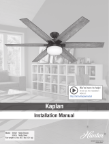
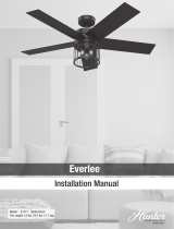
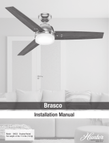
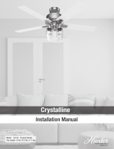
1 Indio
1.1 Installation Manual
1.2 Here are the tools you’ll need to complete your
installation:
1.3 Here is what comes in your box:
1.4 Choosing the Right Installation Location
1.5 Check the room dimensions: Check the outlet box:
1.6 Checking the Ceiling Angle:
1.7 Angled Mounting
1.7.1 A little more information on Angled Mounting:
1.7.2 Hunter Pro Tip:
1.8 Installing the Ceiling Bracket
1.9 Installing the Downrod
1.10 Hanging the Fan
1.10.1 Progress Check:
1.11 Wiring the Fan
1.11.1 Hunter Pro Tip:
1.12 Installing the Canopy
1.13 Installing the Blades:
1.14 Assembling the Light Kit
1.15 Installing the Glass
1.16 Preparing the Remote
1.16.1 Remote Function Guide
1.17 Installing the Remote Control Cradle
1.18 Controlling Your Fan
1.19 Troubleshooting
1.19.1 Fan Doesn’t Work
1.19.2 Excessive Wobbling
1.19.3 Noisy Operation
1.19.4 Remote Control of Fan is Erratic
1.19.5 Multiple Remote Issues
1.20 Downrod
1.21 Limited Lifetime Warranty
1.21.1 How Can Warranty Service Be Obtained?
1.21.2 What Does This Warranty Cover?
1.21.3 What Does This Warranty NOT Cover?
1.21.4 How Does State Law Affect Warranty Coverage?
2 Documents / Resources
2.1 References
3 Related Posts
Indio
Installation Manual
Model: 51420 Matte Nickel
Fan weight ±2 lbs: 21.2 lbs (9.6 kg)
Congratulations on purchasing your new Hunter® ceiling fan!
The ceiling fan you purchased will provide comfort and performance in your home or office for many years. This
instruction manual contains complete instructions for installing and operating your fan. We are proud of our work

and appreciate the opportunity to supply you with the best ceiling fan available anywhere in the world.
We are here to help!
This Instruction Manual is designed to make installation as simple as possible. While working through this
Instruction Manual, keep your smartphone or tablet nearby. We have added video links to help you through the
more technical sections. If you are unfamiliar or uncomfortable with wiring, contact a qualified electrician. We also
provide telephone support at 1.888.830.1326 or visit us at HunterFan.com.
READ and SAVE These Instructions
Warning
w.1 – To reduce the risk of fire, electrical shock, or personal injury, mount fan directly from building structure
and/or an outlet box marked acceptable for fan support of 70 lbs (31.8 kg) and use the mounting screws provided
with the outlet box.
w.2 – To avoid possible electrical shock, before installing or servicing your fan, disconnect the power by turning off
the circuit breakers to the outlet box and associated wall switch location. If you cannot lock the circuit breakers in
the off position, securely fasten a prominent warning device, such as a tag, to the service panel.
w.3 – To reduce the risk of electric shock, this fan must be installed with an isolating wall control/switch.
w.4 – To reduce the risk of personal injury, do not bend the blade brackets when installing the blade brackets,
balancing the blades, or cleaning the fan. Do not insert foreign objects in between rotating fan blades.
w.5 – Chemical burn hazard. Keep batteries away from children. This remote contains a lithium button cell battery.
If a new or used lithium button/coin cell battery is swallowed or enters the body, it can cause severe internal burns
and can lead to death in as little as 2 hours. Always completely secure the battery compartment. If the battery
compartment does not close securely, stop using the product, remove the batteries, and keep it away from
children. If you think batteries might have been swallowed or placed inside any part of the body, seek immediate
medical attention. Dispose of cells properly and keep away from children. Even used cells may cause injury.
w.6 – Non-rechargeable batteries are not to be recharged. Exhausted batteries are to be removed from the
product.
Caution
c.1 – All wiring must be in accordance with national and local electrical codes ANSI/NFPA 70. If you are unfamiliar
with wiring, use a qualified electrician.
c.2 – Use only Hunter replacement parts.
This equipment has been tested and found to comply with the limits for a Class B digital device, pursuant to part
15 of the FCC Rules. These limits are designed to provide reasonable protection against harmful interference in a
residential installation. This equipment generates, uses and can radiate radio frequency energy and if not installed
and used in accordance with the instructions may cause harmful interference to radio communications.
However, there is no guarantee that interference will not occur in a particular installation. If this equipment does
cause harmful interference to radio or television reception, which can be determined by turning the equipment off
and on, the user is encouraged to try to correct the interference by one or more of the following measures:
Reorient or relocate the receiving antenna.
Increase the separation between the equipment and receiver.

Connect the equipment into an outlet on a circuit different from that to which the receiver is connected.
Consult the dealer or an experienced radio/TV technician for help.
Caution: modifications not approved by the party responsible for compliance could void user’s authority to operate
the equipment.
This device complies with Part 15 of the FCC Rules. Operation is subject to the following two conditions: (1) This
device may not cause harmful interference, and (2) this device must accept any interference received, including
interference that may cause undesired operation.
This product conforms to UL Standard 507.
Here are the tools you’ll need to complete your installation:
Ladder Screwdriver
Pliers Wire Strippers
OPTIONAL
If mounting to a support structure, you will also need these tools.

Drill 9/64” Drill Bit
© 2021 Hunter Fan Company
7130 Goodlett Farms Pkwy, Suite 400
Memphis TN 38016
Here is what comes in your box:
We recommend that you pull everything out of the box and lay it out. We have grouped the drawn components
below with the hardware you’ll need for those parts. The screws below are drawn to scale to make it easier to
identify what piece of hardware is needed to install each component.
Hunter Pro Tip:
Do not discard the hardware bags or mix parts from different bags. Make note of the symbol printed
on each hardware bag. The symbols can be used to identify the appropriate hardware for each
step.
x2
BAG Wood Screw
Washer x2 Wire Nut x4
For installing the hanger bracket and wiring the fan

Ceiling Bracket
Canopy Screw x2
For installing the canopy
Downrod
Blade x5
For installing the blades
Motor
Upper Switch Housing

Light Kit
Bulb x2
Glass
x3 x2
BAG Light Kit Screw Short Light Kit Screw
For installing the light kit
Remote Control Remote Cradle Remote Receiver
Remote Components
Extra downrod

BAG Spare Parts
For your convenience, you may receive extra fasteners.
Note:
Fan style may vary.
Find a part that is missing or damaged?
Don’t take it back to the store. Let us make it right. Visit us at HunterFan.com or call us at
1.888.830.1326.
M3879-01 r032221
Choosing the Right Installation Location
You probably bought this fan with a location in mind. Let’s check below to make sure it is a good fit.
Check the room dimensions: Check the outlet box:
You must be able to secure the fan to building
structure or fan-rated outlet box.
Checking the Ceiling Angle:
Standard Mounting

If you have a flat ceiling:
Hang your fan by a standard downrod. Some fans come with a shorter downrod for a Low Profile installation.
If you have an angled or vaulted ceiling:
1. You will need a longer downrod. (sold separately at HunterFan.com)
2. If your ceiling angle is greater than 34°, you will also need an Angled Mounting Kit. (Sold separately at
HunterFan.com)
Angled Mounting
A little more information on Angled Mounting:
For optimum performance and appearance, a longer downrod should be used with your Hunter ceiling fan when
installing on high or angled ceiling. If your ceiling is angled greater than 34° you will also need an Angled Mounting
Kit. Longer downrods and the Angled Mounting Kit are sold separately at HunterFan.com.
Hunter Pro Tip:
Determining if you need an Angled Mounting Kit:
Fold on the dotted line. Place against edge against the wall. Slide towards the ceiling.
If the guide touches the wall but not the ceiling, you need an angled mounting kit.
Installing the Ceiling Bracket

You have two options for installation. Pick which one works best for your location. Remove any existing bracket
prior to installation. Only use the provided Hunter ceiling bracket that came in your fan’s box.
Do this first!
To avoid possible electrical shock, before installing your fan, disconnect the power by turning
off the circuit breakers to the outlet box associated with the wall switch location.
Option 1:
Machine Screws
Use machine screws (provided with outlet box) and washers when securing to existing ceiling fan-rated outlet
box. Make sure it is securely installed and is acceptable for fan support of 31.8 kg (70 lbs) or less.
ANGLED MOUNTING TIP
For angled ceilings, point opening toward peak.
Option 2:
Wood Screws
Use wood screws and washers (included) when securing to support structure with approved electrical outlet box.
Drill 9/64″ pilot holes in support structure to aid in securing ceiling bracket with hardware found in the
hardware bag.
Hunter Pro Tip:
The machine screws are the ones that came with your outlet box.

Installing the Downrod
Follow below if you are using the downrod that came pre-assembled in your box. Need to install a longer or
shorter downrod? Check out the guide at the end of this manual.
Remove the pre-installed setscrew so that the downrod can be inserted.
Hunter Pro Tip:
The ground wire attached to the downrod is approximately 8 inches.
Pass all wires to one side of horizontal bar in downrod assembly. Hand tighten the downrod (at least 4–5 full
turns) until it stops. Trim the wires coming from the fan so that 8-inches remain coming from the top of the
downrod.

Tighten the setscrew with pliers. DO NOT HAND TIGHTEN.
FAN FALL HAZARD
To prevent SERIOUS INJURY or DEATH:
ALWAYS tighten setscrew with pliers.
DO NOT hand tighten setscrew.
CHECK the setscrew is tight using pliers each time you change fan direction.
Hanging the Fan
NOTICE
To prevent damage to fan, ALWAYS lift holding either the fan housing or the downrod.
Place the downrod ball into the slot in the ceiling bracket.
Progress Check:
Your fan should look like this.

Note:
Fan style may vary.
Wiring the Fan
We know wiring is hard. Let’s make it easier.
Follow these steps to get your fan wired quickly and safely. Follow the route below that best matches your wall
switch setup. If you are unfamiliar with wiring or uncomfortable doing it yourself, please contact a qualified
electrician.
Hunter Pro Tip:
Here is how to connect the wires:
Push the bare metal ends of the wires together and slide a wire nut over them. Then, twist the wire nut clockwise
until tight.
Give it a gentle pull to make sure none of the wires are loose.
Slide the remote receiver onto the top of the bracket.
The ceiling fan must be grounded. If the ground wire for the installation site is not present, immediately STOP
installation and consult a qualified electrician.

All wiring must be in accordance with national and local electrical codes ANSI/NFPA 70. If you are unfamiliar with
wiring or in doubt, consult a qualified electrician.
Hunter Pro Tip:
Have extra wiring?
Turn the wires upward and push them carefully back through the hanger bracket into the outlet box. Spread the
wires apart, with the grounded wires on one side of the outlet box and the ungrounded wires on the other side of
the outlet box. Make sure that the wires are still attached to the wire nuts.
1. Connect the yellow wire from the receiver to the black wire from the fan.
2. Connect the three grounding wires (green, green/yellow stripe, or bare copper) coming from the ceiling,
downrod, and hanging bracket.
3. Connect the blue wire from the receiver to the blue wire from the fan.
4. Connect the white (grounded) wire from the ceiling to both the white wire from the receiver and the white wire
from the fan.
5. Connect the black (ungrounded) wire from the ceiling to the black wire from the receiver.
Note:
Fan style may vary.
DR19-01 r091420
Installing the Canopy

Lift the canopy into place so that the screw holes are aligned.
Insert the two canopy screws found in the hardware bag.
Installing the Blades:

Attach each blade to a blade iron
using three blade washers, found in
the hardware bag, and three blade
assembly screws, found in the
hardware bag.
Repeat x5
Note:
Fan style may vary.
NOTE: Follow the instructions on the blade. Installing it incorrectly could result in your fan not functioning.
Assembling the Light Kit
Partially install two light kit assembly screws, found in the hardware bag, halfway into the motor housing as
shown. It does not matter which two screw holes you choose.

Feed the wire plugs through the center hole of the upper switch housing, then wrap keyhole slots around the
screws and twist counterclockwise.
Insert the third screw, found in the hardware bag, into place and then tighten all three screws.
Partially install two of the light kit screws found in the bag. It does not matter which two screw holes you
choose. Connect the single-pin connectors from the LED assembly to the connectors from the fan. Connect the
white wires together. Connect the blue and black wires together.

Align the keyhole slots in the light kit housing with the two screws. Make sure all the wires from the fan and the
light kit are snug inside the center of the light kit, not pinched in between the upper switch housing and the light kit
or hanging out of the sides.
Turn the light kit counterclockwise until the light kit screws are firmly situated in the narrow end of the keyhole
slots. Install the third screw and tighten all three screws securely.
Note:
Fan style may vary.

FAN FALL HAZARD
Make sure all screws are tight to secure the light fixture.
Installing the Glass
1. Install the included bulbs into the sockets. When necessary, replace with bulbs of same wattage.
2. Lift the globe and align the notches in the globe with the tabs in the light kit.
3. Attach the globe by lifting and turning clockwise one third of a full turn of the glass until it stops.
NOTE: Check to ensure proper engagement.
Note:
Fan style may vary.
GLASS FALL HAZARD
To prevent SERIOUS INJURY or DEATH, make sure that glass is properly secured.
Preparing the Remote
The remote control is already paired for use. For your convenience, a remote function card is packed in
with your remote.
NOTICE
Always purchase the correct size and grade of battery most suitable for the intended use.
Replace all batteries of a set at the same time.
Clean the battery contacts and also those of the device prior to battery installation.
Ensure the batteries are installed correctly with regard to polarity (+ and -).
Remove batteries from equipment which is not to be used for an extended period of time.
Remove used batteries promptly.

1. To access the battery compartment, remove the small Phillips head screw that secures
the battery door to the transmitter assembly. The battery should be installed with the
positive (+) side up. Replace with a CR2032 battery when necessary.
Remote Function Guide
Key Press Function
+ Quick Press Light On/Off
+ Long Press Light Dimming
+ Quick Press Fan On/Off
+ Quick Press Raise Fan Speed
+ Quick Press Lower Fan Speed
Long Press Fan High
Long Press Fan Low
Long Press + Dimming Mode On/Off
Installing the Remote Control Cradle
You have two options for installing the remote cradle.
Choose which path works best for you.
/