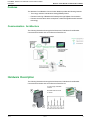
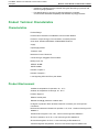
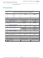
Schneider Electric BCMWV1 is a wireless circuit breaker communication module that provides advanced monitoring and control capabilities for your electrical system. With Bluetooth Low Energy and ZigBee connectivity, you can easily pair it with the EcoStruxure Power Commission mobile app for remote monitoring and firmware updates. The BCMWV1 offers real-time metering, alarm notifications, and energy reduction maintenance settings to optimize your energy usage and improve electrical safety.
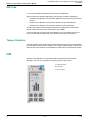
Schneider Electric BCMWV1 is a wireless circuit breaker communication module that provides advanced monitoring and control capabilities for your electrical system. With Bluetooth Low Energy and ZigBee connectivity, you can easily pair it with the EcoStruxure Power Commission mobile app for remote monitoring and firmware updates. The BCMWV1 offers real-time metering, alarm notifications, and energy reduction maintenance settings to optimize your energy usage and improve electrical safety.


-
 1
1
-
 2
2
-
 3
3
-
 4
4
-
 5
5
-
 6
6
-
 7
7
-
 8
8
-
 9
9
-
 10
10
-
 11
11
-
 12
12
-
 13
13
-
 14
14
-
 15
15
-
 16
16
-
 17
17
-
 18
18
-
 19
19
-
 20
20
-
 21
21
-
 22
22
-
 23
23
-
 24
24
-
 25
25
-
 26
26
-
 27
27
-
 28
28
-
 29
29
-
 30
30
-
 31
31


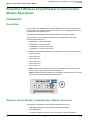
Schneider Electric BCMWV1 is a wireless circuit breaker communication module that provides advanced monitoring and control capabilities for your electrical system. With Bluetooth Low Energy and ZigBee connectivity, you can easily pair it with the EcoStruxure Power Commission mobile app for remote monitoring and firmware updates. The BCMWV1 offers real-time metering, alarm notifications, and energy reduction maintenance settings to optimize your energy usage and improve electrical safety.
Ask a question and I''ll find the answer in the document
Finding information in a document is now easier with AI
Related papers
-
Schneider Electric MasterPact, ComPacT, PowerPacT - Cybersecurity User guide
-
-
Schneider Electric PacT Series User guide
-
Schneider Electric 2.0A User manual
-
Schneider Electric PowerPact User manual
-
-
Schneider Electric Galaxy VL User guide
-
-
-
