www.abhmfg.com
Architectural Builders Hardware Mfg., Inc.
1222 Ardmore Ave., Itasca, IL 60143
630.875.9900; FAX 800.9FAXABH (932.9224)
O
R
c 2021 ABH Mfg., Inc.
printed in USA REVISED 10-25-21
PAGE 2 OF 2
ABH is a minority
owned and operated
manufacturing company.
2100-2-04.DWG
2100
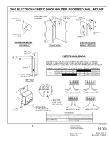
2100 ELECTROMAGNETIC DOOR HOLDER, RECESSED, WALL MOUNT
1" Extension
*
*
Lock Edge
of Door
Approx.
2-5/8"
2-5/8"
1"
WALL PORTION INSTALLATION:
1. Measure distance from pivot centerline to wall (Dim. "A").
2. Determine door width (Dim. "B").
3. Use table below to locate magnet box on wall (Dim. "C").
a. Example : Dim. "A" = 10" Dim. "B" = 42" Result Dim. "C" = 38-7/8".
b. If Dim. "A" or Dim. "B" falls between dimensions listed in the table
below, allow for difference.
Example : Dim. "A"= 7" Dim. "B" = 36" Then Dim."C" = 33-1/8".
c. If Dim. "A" and Dim. "B" intersect in the shaded area, DO NOT INSTALL magnet box.
The degree of door opening will not allow for proper alignment between armature and
wall magnet.
4. Suggested vertical location is on top rail approximately 5" from top of the door.
5. Check degree of door opening shown in table and coordinate with door closer and
other door hardware.
6. Total projection of door hardware must not be more than 3-5/8" on the pull side of door.
If greater, you will need to use additional extensions, sold separately.
7. From corner of wall, measure the appropriate Dim. "C" determined in step 3.
8. Proper electrical wire routing must be done before installing magnet box.
9. The 4" x 2-1/8" x 2" outlet box (not provided with unit) should be installed with
reinforcement to withstand a minimum 50 lb. pull.
IMPORTANT : Check that power voltage equals voltage labeled on back of magnet.
Consult " ELECTRICAL DATA" on page 1.
DOOR ARMATURE INSTALLATION:
1. Place and center the door armature on the surface of the magnet with the two
holes of the base aligned horizontally.
2. Gently close the door and adjust the angle of the door armature so the base
lays flat against the door.
3. While keeping slight pressure on the door, mark location of door armature
through the two base holes.
4. Drill through the door where the two marks are located with 5/16" drill.
Fasten with the (2)10-32 machine screws & sex bolts provided.
For 2-5/8" Door Projection,
use 1" Extension provided
complimentry
C
A
B
Pivot
Centerline
Magnet Box
Centerline
2-3/4"
4-5/8"
1"
NOTE: 1. All dimensions are provided in inches, unless noted otherwise.
2. Additional extensions can be ordered separately to increase the
door armature projection : 3/8", 1/2", 3/4", 1", 2", 4" or 6".
1-3/4"
1-5/8"
41-3/8 88°
41-3/8 91°
41-1/4 93°
41-1/8 96°
41 99°
40-1/2 102°
40 105°
39-1/2 107°
38-3/4 110°
38 113°
37 116°
36 120°
Dim"C" Deg
25-5/8 119°
26-5/8 115°
27-1/2 111°
28-1/8 107°
28-5/8 103°
29 99°
29-5/8 95°
29-3/8 91°
29-3/8 87°
Dim "C" Deg
27-1/8 87°25-3/8 86°
22-1/8 119°
23-1/8 114°
24 109°
24-1/2 105°
25 100°
25-1/4 95°
25-3/8 91°
24-3/8 112°
24-1/4 122°
24-3/8 117°
26 108°
26-5/8 103°
27 99°
27-1/4 95°
27-3/8 91°
Dim"C" Deg
28
Dim"C" Deg
30
30-3/8 121°
31-3/8 118°
32-3/8 114°
33-1/8 110°
33-7/8 107°
34-3/8 104°
34-3/4 100°
35-1/8 97°
35-1/4 94°
35-3/8 91°
35-3/8 87°
Dim "C" Deg
33-3/8 87°31-3/8 87°
26-3/4 123°
27-7/8 117°
28-7/8 113°
29-5/8 109°
30-1/4 105°
30-3/4 102°
31 98°
31-1/4 94°
31-3/8 91°
31-3/4 108°
27-7/8 123°
29 119°
30-1/8 116°
31 112°
32-3/8 105°
33 101°
33 98°
33-1/4 94°
33-3/8 91°
Dim "C" Deg
32 34
Dim "C" Deg
36
39-3/8 88°37-3/8 88°
31-3/8 123°
37-1/8 97°
36-7/8 100°
36-3/8 103°
35-7/8 106°
35-1/4 109°
34-1/2 113°
33-5/8 116°
32-1/2 119°
37-1/4 94°
37-3/8 91°
38 105°
37-3/8 108°
36-3/4 111°
35-3/4 115°
34-7/8 118°
33-3/4 121°
39-3/8 91°
39-1/8 96°
38-7/8 99°
38-1/2 102°
39-1/4 93°
Dim"C" Deg
38 40
Dim"C" Deg
42
45-3/8 88°43-3/8 88°
43-3/8 90°
43-1/8 96°
43 98°
42-1/8 104°
41-5/8 107°
41 109°
42-1/2 101°
40-1/8 112°
39-1/4 115°
38-1/4 118°
43-1/4 93°
44-1/8 103°
43-5/8 106°
43 108°
42-3/8 111°
41-1/2 114°
40-1/2 117°
45-3/8 90°
45-1/8 96°
45 98°
44-5/8 101°
45-1/4 93°
Dim "C" Deg
44 46
Dim "C" Deg
48
DIM. "B" (DOOR WIDTH)
2
4
6
8
10
12
14
16
18
20
22
24
Dim.
"A"