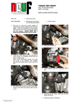
MS100143

APR MS100143 Installation guide

  • Hello! I've reviewed the installation manual for the APR MQB High Pressure Fuel Pump (HPFP), specifically models MS100143 and MS100144. This document provides detailed instructions for replacing your car's original fuel pump with the new one, including torque specifications and connection guidance. I'm ready to answer any questions you have about the installation process.
  • What should I use to organize fasteners during disassembly?
    What should I do before pulling the fuel feed line off the pump?
    What torque is required for the two 10mm triple square screws holding the HPFP?
#TL100147
MS100143,144
APR MQB High Pressure Fuel Pump (HPFP)
TL100147
WWW.GOAPR.COM
4800 US HWY 280 West Opelika Alabama 36801
Notes:
These instructions were written for a North American specication VW Mk7 GLI, but
other models, like the A3, S3, GTI and Golf R are similar.
When disassembling the car, be sure to keep all fasteners so they can be reused. It is
recommend that you get some kind of compartmented tray to organize the fasteners,
such as a shing tackle box or several large ice cube trays. Fasteners that are not
reused for reinstallation are noted in the instructions. All directions used in this manual
(right, left, front, etc.) are based on if you were sitting in the drivers seat of the car.
These instructions assume that you have basic mechanical skills and several varieties
of basic hand tools in order to install the kit. If you have any questions about the install,
feel free to contact your APR representative.
1) Raise the hood and remove the
engine cover. Remove the intake
from the turbo inlet as well as remove
the airbox from the car. Use a rag to
prevent anything from falling into the
turbocharger.
TL100147
2) Remove the two T30 screws from
the coolant pipe that runs along the
left side of the engine.
3) Remove the spring clamp from
the end of the fuel feed line. Wrap
the hose and connection with a rag
before pulling the hose o of the
pump, as gas will drain and can
spray from the port in the HPFP.
TL100147
4) Disconnect the electrical connec-
tor from the top of the HPFP.
5) Remove the T30 screw from the
side of the turbo outlet pipe.
TL100147
6) Move the turbo outlet pipe out of
the way to access the T30 screw that
holds the HPFP outlet pipe.
7) Loosen the 17mm nut from the
HPFP outlet pipe. Some fuel will
drain from here was well.
TL100147
8) Remove the two 10mm triple
square screws holding the HPFP to
the cylinder head.
9) Pull the HPFP away from the
engine just enough to pull the o-ring
out of the housing in the cylinder
head. Then, rotate the HPFP coun-
ter-clockwise to separate the pump
from the outlet pipe. Remove the
pump from the car. It is not neces-
sary to remove the roller tappet from
inside the cylinder head.
TL100147
10) Lubricate the o-ring on the APR
pump with engine oil, and then place
the APR HPFP into the housing on
the cylinder head with the pump
slighly rotated counter-clockwise.
Do not push the pump into the head.
Ensure the tting on the bottom of
the APR HPFP aligns with the outlet
pipe, then rotate the pump clockwise
until the bolt holes line up.
11) Ensure the outlet pipe sits cor-
rectly into the connection on the
bottom of the APR HPFP. Install the
two 10mm triple square screws and
tighten to 20Nm (177in-lbs).
TL100147
12) Install the 17mm nut holding the
bottom of the outlet pipe to the APR
HPFP. Tighten the tting to 27Nm
(20ft-lbs).
13) Reconnect the electrical con-
nector to the solenoid on the top of
the APR HPFP. Reinstall the fuel
feed line to the front of the APR
HPFP, and secure with the original
spring clamp.
TL100147
14) Reinstall the T30 screw holding
the HPFP outlet pipe to the intake
manifold, and tighten the screw to
9Nm (80in-lbs).
15) Reinstall the T30 screw hold-
ing the charge pipe to the intake
manifold. Tighten this screw to 7Nm
(62in-lbs).
TL100147
16) Reinstall the two T30 screws
holding the coolant pipe to the side
of the engine. Torque both screws to
9Nm (80in-lbs).
17) Place the intake back in the car,
reconnecting the vacuum line to the
bottom of it. Be sure all three mount-
ing grommets are in place. Tighten
the clamp holding the back of the
intake to the turbocharger inlet.
Finally, reinstall the engine cover.
/