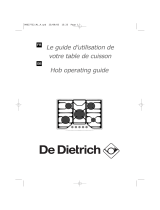
De Dietrich DTG1138X Owner's manual

Category
Hobs
Type
Owner's manual
FR GUIDE D'INSTALLATION ET D’UTILISATION
EN GUIDE TO INSTALLATION AND USE
ES MANUAL DE INSTALACIÓN Y UTILIZACIÓN
PT GUIDE D'INSTALLATION ET D’UTILISATION
DE EINBAU- UND GEBRAUCHSANWEISUNG
Table de cuisson
Cooking Hob
Placa de cocción
Placa de cozinha
Kochfeld
CHOIX DE L’EMPLACEMENT
La table de cuisson doit être encastrée dans
le plateau d'un meuble support de 3 cm d'é-
paisseur minimum, fait en matière qui résiste
à la chaleur, ou bien revêtu d'une telle matière.
Pour ne pas gêner la manoeuvre des ustensi-
les de cuisson, il ne doit y avoir à droite, ou à
gauche, ni meuble ni paroi à moins de 30 cm
de la table de cuisson.
Si une cloison horizontale est positionnée
sous la table, celle-ci doit être située impérati-
vement entre 100 et 150 mm par rapport au-
dessus du plan de travail. Dans tous les cas,
ne rangez pas d’atomiseur ou de récipient
sous pression dans le compartiment qui pour-
rait exister sous la table
AVANT L’INSTALLATION
de votre appareil, et pour assurer l'étanchéité
entre le caisson et le plan de travail, collez le
joint mousse sur le pourtour extérieur du ca-
dre
(Fig. 02).
1- Retirez les grilles support casserole, les
chapeaux de brûleur et les têtes de brûleurs
en repérant leur position.
2- Retournez la table et posez-la avec précau-
tion au-dessus de l’ouverture du meuble pour
ne pas endommager les bougies d’allumage.
3- Collez le joint mousse, livré avec l'appareil,
sur le pourtour extérieur du cadre. Ce joint
assure l'étanchéité entre le verre et le plan de
travail.
4- Replacez les têtes de brûleurs, les cha-
peaux de brûleurs et les grilles.
FR2 / INSTALLATION DE VOTRE APPAREIL
49 cm
3 cm mini
10 cm mini
10 cm mini
34 cm
7,5 cm mini
70 cm mini
Joint
Fig. 01
Fig. 02
7
APPAREIL
M
ODÈLE
L
ARGEUR
P
ROFONDEUR
E
PAISSEUR
Découpe
meuble
34 cm 49 cm suivant
meuble
Dimensions
hors tout au-
dessus
du plan de
travail
38 cm 52cm 5 cm
Dimensions
hors tout au-
dessous
du plan de
travail
34 cm 48 cm 5,1 cm
14
FR
2 / INSTALLATION DE VOTRE APPAREIL
CHANGEMENT DE GAZ (SUITE)
Changez les injecteurs en procédant
comme suit :
— Retirez les grilles, les chapeaux, et les têtes
de tous les brûleurs.
— Dévissez à l’aide de la clé fournie les
injecteurs situés dans le fond de chaque pot
et ôtez-les
(Fig. 01).
— Montez à la place les injecteurs du gaz
correspondants, conformément au repérage
des injecteurs et au tableau des
caractéristiques gaz en fin de chapitre ; pour
cela :
— Vissez-les d’abord manuellement jusqu’au
blocage de l’injecteur.
— Engagez la clé correspondante sur
l’injecteur.
— Tracez une ligne sur la plaque d’âtre à l’aide
d’un crayon à l’endroit indiqué
(Fig. 02).
— Tournez la clé dans le sens des aiguilles
d’une montre jusqu’à ce que la ligne
apparaisse de l’autre côté
(Fig. 03).
Attention
Ne pas dépasser cette limite sous
peine de détérioration du produit.
— Remontez une la tête di brûleur, le chapeau
et la grille.
Branchez le cordon électrique de la table
sur votr réseau (220-240 V
˜
) monophasé. Re-
portez-vous au paragraphe “Raccordement
électrique”.
Attention
Vissez l’injecteur avec un couple de
serrage ne dépassant pas 4 N.m.
Ne pas dépasser cette limite sous peine de
détérioration du produit..
Pour la table 2 feux
Fig. 02
Fig. 03
Ligne
Ligne
Clé
Clé
Fig. 01
Clé
Injecteur
Pot
19
•Caractéristiques gaz
FR2 / INSTALLATION DE VOTRE APPAREIL
Table 2 feux
DTG1138X*
Table 1 feu forte puissance
DTG1138X*
FR-CH
ES-IT
PT
FR-CH
ES-IT
PT
FR-CH
ES-IT
PT-CY
EE - PL
LT
FR
Appareil destiné à être installé en : Butane Propane Gaz Gaz
naturel naturel
FR ..............................cat : II2E+3+
CH - ES - IT - PT........cat : II2H3+ G30 G31 G20 G25
CY - EE - PL...............cat : II2H3B/P
LT ...............................cat : I2H
Débit horaire ci-dessous : 28-30 mbar 37mbar 20 mbar 25 mbar
à 15°C sous 1013 mbar
B
RÛLEUR TRIPLE COURONNE
Repère marqué sur l'injecteur 90A 90A 45A 45A
Débit calorifique nominal (kW) 3,20 3,20 3,50 3,50
Débit calorifique réduit (kW) 1,650 1,450 1,450
Débit horaire (g/h) 233 229
Débit horaire (l/h) 333 388
B
RÛLEUR AUXILIAIRE
Repère marqué sur l'injecteur 45 45 63 63
Débit calorifique nominal (kW) 0,70 0,70 0,85 0,85
Débit calorifique réduit (avec sécurité) (kW) 0,350 0,470 0,470
Débit horaire (g/h) 51 50
Débit horaire (l/h) 81 94
BOTAL TABLE 2 FEUX GAZ 38 CM
AVEC BRÛLEURS TRIPLE COURONNE ET AUXILIAIRE
Débit calorifique total (kW) 3,90 3,90 4,35 4,35
Débit maximum (g/h) 284 279
(l/h) 414 482
B
RÛLEUR FORTE PUISSANCE :
BRÛLEUR CENTRAL
Repère marqué sur l'injecteur 49B 49B 74B 74B
Débit calorifique nominal (kW) 1,05 1,05 1,05 1,05
Débit calorifique réduit (avec sécurité) (kW) 0,680 0,800 0,800
Débit horaire (g/h) 76 75
Débit horaire (l/h) 100 116
BRÛLEUR FORTE PUISSANCE :
BRÛLEUR TOTAL
Repère marqué sur l'injecteur 49B / 63B 74B / 97B
Débit calorifique nominal (kW) 5,60 5,60 5,95 5,95
Débit calorifique réduit (avec sécurité) (kW) 2,700 2,850 2,850
Débit horaire (g/h) 407 400
Débit horaire (l/h) 567 659
20
FR
2 / INSTALLATION DE VOTRE APPAREIL
Le tableau ci-dessous indique les
implantations des injecteurs sur votre
appareil en fonction du gaz utilisé.
Chaque numéro est marqué sur l’injecteur.
REPERAGE DES INJECTEURS
Table 38 cm avec foyers
auxiliaire + triple couronne
63
Gaz Naturel
45A
63
90A
45
Gaz butane/
Propane
Exemple :
repère injecteur 63
Table 38 cm avec foyer
forte puissance
Gaz Naturel
97B
74B
97B
97B
Gaz Butane/Propane
63B
49B
63B
63B
21
DESCRIPTION DE VOTRE DESSUS
Modèle 2 feux gaz à commandes électroniques
(DTG 1138*)
Modèle 1 feu gaz forte puissance à commandes électroniques
(DTG 1008*)
FR3 / UTILISATION DE VOTRE APPAREIL
B
A
C
A
B
Foyer auxiliaire 0,85 kW (
*
)
Brûleur triple couronne 3,6 kW (
*
)
Brûleur forte puissance 6,1 kW (
*
)
C
(
*
) Puissances obtenues en gaz naturel G20.
33
Les éventuelles interventions sur votre
appareil doivent être effectuées par un profes-
sionnel qualifié dépositaire de la marque. Lors
de votre appel, mentionnez la référence
complète de votre appareil (modèle, type,
numéro de série). Ces renseignements
figurent sur la plaque signalétique
(Fig. 01).
PIÈCES D’ORIGINE
Lors d’une intervention d’entretien, demandez
l'utilisation exclusive de
pièces détachées
certifiées d’origine.
•INTERVENTIONS
C
E
DTI702
Fig. 01
Pour préserver votre appareil, nous vous recommandons d'utiliser les produits d'entretien
Clearit.
Clearit vous propose des produits professionnels et des solutions adaptées pour l'entretien
quotidien de vos appareils électroménagers et de vos cuisines.
Vous les trouverez en vente chez votre revendeur habituel, ainsi que toute une ligne de
produits accessoires et consommables.
L'expertise des professionnels au service des particuliers
FR7 / SERVICE APRES-VENTE ET RELATIONS CONSOMMATEURS
•Pour en savoir plus sur tous les produits
de la marque :
informations, conseils, les points de vente,
les spécialistes après-vente.
•Pour communiquer :
nous sommes à l'écoute de toutes vos
remarques, suggestions, propositions
auxquelles nous vous répondrons
personnellement.
> Vous pouvez nous écrire :
Service Consommateurs
DE DIETRICH
BP 9526
95069 CERGY PONTOISE CEDEX
> ou nous téléphoner au :
*Tarif minimum selon opérateur
•RELATIONS CONSOMMATEURS
*Service fourni par FagorBrandt SAS, locataire-gérant, Etablissement de Cergy, 5/7 avenue des Béthunes,
95310 Saint Ouen L’Aumône SAS au capital social de 20 000 000 euros RCS Nanterre 440 303 196.
FagorBrandt SAS, locataire-gérant – SAS au capital social de 20 000 000 euros RCS Nanterre 440 303 196.
35
1 / USER NOTICES
• Safety instructions . . . . . . . . . . . . . . . . . . . . . . . . . . . . . . . . . . . . . . . . . . . . . . . 36
• Caring for the environment . . . . . . . . . . . . . . . . . . . . . . . . . . . . . . . . . . . . . . . . 37
• Description of your Hob . . . . . . . . . . . . . . . . . . . . . . . . . . . . . . . . . . . . . . . . . . 38
2 / INSTALLING YOUR APPLIANCE
• Correct positioning . . . . . . . . . . . . . . . . . . . . . . . . . . . . . . . . . . . . . . . . . . . . . . 39
• Before installing . . . . . . . . . . . . . . . . . . . . . . . . . . . . . . . . . . . . . . . . . . . . . . . . . 39
• Tips for flush mounting . . . . . . . . . . . . . . . . . . . . . . . . . . . . . . . . . . . . . . . . . . . 40
• Flush fitting above a unit with door or drawer . . . . . . . . . . . . . . . . . . . . . . . . 40
• Electrical connection . . . . . . . . . . . . . . . . . . . . . . . . . . . . . . . . . . . . . . . . . . . . . 41
• Gas connection . . . . . . . . . . . . . . . . . . . . . . . . . . . . . . . . . . . . . . . . . . . . . . . . . 42
• Changing the gas supply . . . . . . . . . . . . . . . . . . . . . . . . . . . . . . . . . . . . . . . . . 45
3 / USING YOUR APPLIANCE
• Description of your hob
(2-gas burner model with electronic controls) . . . . . . . . . . . . . . . . . . . . . . . 53
(1 high-power gas burner model with electronic controls) . . . . . . . . . . . . . . 53
• Lighting the gas burners . . . . . . . . . . . . . . . . . . . . . . . . . . . . . . . . . . . . . . . . . 54
• Turning off . . . . . . . . . . . . . . . . . . . . . . . . . . . . . . . . . . . . . . . . . . . . . . . . . . . . . 54
• Adjusting the power level . . . . . . . . . . . . . . . . . . . . . . . . . . . . . . . . . . . . . . . . . 54
• Description of the controls (1 high-power burner model) . . . . . . . . . . . . . . 55
• Lighting the gas burners . . . . . . . . . . . . . . . . . . . . . . . . . . . . . . . . . . . . . . . . . 55
• Turning off . . . . . . . . . . . . . . . . . . . . . . . . . . . . . . . . . . . . . . . . . . . . . . . . . . . . . 55
• Adjusting the power level . . . . . . . . . . . . . . . . . . . . . . . . . . . . . . . . . . . . . . . . . 55
• Turning on the cooking zones and adjusting the power . . . . . . . . . . . . . . . 56
• Using the timer (1 high-power burner model) . . . . . . . . . . . . . . . . . . . . . . . . 57
• Using the timer (2-gas burner model) . . . . . . . . . . . . . . . . . . . . . . . . . . . . . . . 58
• Cookware suitable for gas burners . . . . . . . . . . . . . . . . . . . . . . . . . . . . . . . . . 59
4 / DAILY CARE OF YOUR APPLIANCE
• Maintaining your appliance . . . . . . . . . . . . . . . . . . . . . . . . . . . . . . . . . . . . . . . . 60
5 / SMALL FAULTS AND PROBLEMS . . . . . . . . . . . . . . . . . . . . . . . . . . . . . . . . . . . 61
6 / COOKING GUIDE
• Guide to cooking with the 2-burner hob . . . . . . . . . . . . . . . . . . . . . . . . . . . . . 64
• Guide to cooking with the 1 high-power burner hob . . . . . . . . . . . . . . . . . . 64
7 / AFTER-SALES SERVICE AND CUSTOMER RELATIONS
• Service calls . . . . . . . . . . . . . . . . . . . . . . . . . . . . . . . . . . . . . . . . . . . . . . . . . . . . 65
ENCONTENTS
36
SAFETY INSTRUCTIONS
We have designed this cooking hob for use
by private individuals in their homes.
As part of our commitment to constantly
improving our products, we reserve the right
to make changes to them based on
technological advances to their technical,
functional and/or aesthetic properties.
This hob must be installed in accordance
with current regulations and used only in a
well-ventilated area. Consult this guide before
installing and using your appliance.
Never leave the appliance unattended when
in use.
These cooking hobs are intended
exclusively for cooking beverages and
foodstuffs and do not contain any asbestos-
based materials.
This appliance is not connected to a
combustion by-product disposal system. It
must be installed and connected in
accordance with current regulations. Special
attention should be given to regulations
regarding the proper levels of ventilation.
Do not store
CLEANING or INFLAMMABLE
PRODUCTS (aerosol cans, pressurised
containers, papers, cookbooks, etc.) in the
area underneath your hob.
— If the hob has been installed over a drawer,
we recommend that you avoid using it to
store flammable items (plastics, papers,
aerosol cans, etc.).
Your hob must be disconnected from the
power supply (electricity and gas) before
undertaking any repair work.
If you plug electrical appliances into a
socket close to the hob, ensure that no cable
comes into contact with the hotplates and
burners.
As a safety measure, remember to shut off
the mains gas supply or the butane/propane
gas cylinder when not in use.
The CE compliance designation is affixed
to these hobs.
Installation should only be undertaken by
qualified fitters and technicians.
Before installation, ensure that the
conditions of local distribution (gas type and
pressure) and the settings of the appliance
are compatible.
This appliance is not intended for use by
persons (including children) with impaired
physical, sensory or mental capacities, or by
inexperienced or untrained persons, unless
they have received prior instruction or
supervision in its operation by a person
responsible for their safety.
Children must be supervised to prevent
them from playing with the appliance.
This hob complies with the EN 60335-2-6
standard with regard to the heating of
cabinets and the Class 3 standard with regard
to installation (according to the EN 30-1-1
standard).
Note
- The setting conditions for this hob are
printed on a sticker inside the instruction
guide pouch and on the packaging.
- So that you can easily locate any
reference numbers for your appliance, we
recommend that you make a note of them
on the “After-Sales Service and Customer
Relations” page (this page also explains
where this information may be found on
your appliance).
If a crack appears in the surface of the
glass, disconnect your appliance from the
power supply to avoid electric shock.
Contact the After-Sales Service department.
EN
1 / USER NOTICES
Important
Keep this user guide with your
appliance. If the appliance is ever sold or
transferred to another person, ensure that
the new owner receives this user guide.
Please become familiar with these
recommendations before installing and
using your oven. They were written for your
safety and the safety of others.
YOUR HOB IS NOW READY TO BE USED WITH NATURAL GAS
37
— This appliance’s packing materials are
recyclable. Recycle them and help to protect
the environment by disposing of them in the
council receptacles provided for this
purpose.
Your appliance also contains
various recyclable materials. It is
therefore marked with this logo to
indicate that, in European Union
countries, used appliances must
not be mixed with other waste.
Appliance recycling organised by
your manufacturer will thus be carried out in
optimum conditions, in accordance with
European directive 2002/96/EC on waste
electrical and electronic equipment. Consult
your local authority or your retailer to find the
drop-off points for used appliances nearest
to your home.
We thank you for your help in protecting the
environment.
CARING FOR THE ENVIRONMENT
EN1 / USER NOTICES
38
DESCRIPTION OF THE HOB
Tip
This Guide to Installation and Use is valid for several models. There may be minor
differences between the details and fittings on your appliance and the description provided.
EN
1 / USER NOTICES
Burner
A
B
C
D
E
Burner covers
Burner head
Injector
Spark igniter
Thermocouple
Keypad
Hob model: 2 gas burners
with touch-sensitive controls
Grid
support pan
Hob with 1 high-power gas burner
and touch-sensitive controls
F
F
Grid
support pan
D
C
B
A
E
A
B
C
D
E
F
Burner
CORRECT POSITIONING
Your hob should be built into the top of a sup-
porting cabinet. The worktop should be at
least 3 cm thick, and made of a heat-resistant
material or a material with a heat-resistant
coating.
To ensure that cooking utensils can be han-
dled safely, a minimum of 30 cm either side of
the hob should be kept free from any obstruc-
tions (cabinets or walls).
If a horizontal partition is positioned under the
hob, it must be located between 100 and
150 mm from the top of the work surface. In
any event, do not store aerosol cans or con-
tainers under pressure in any compartment
that may exist under the hob
BEFORE INSTALLING
your appliance and to ensure leaktightness
between the frame and the worktop, stick the
foam seal around the edge of the frame
(Fig. 02).
1- Remove the pan supports, the burner cov-
ers and burner heads, noting their positions.
2- Turn the hob over and carefully place it on
top of the opening in the cabinet so as not to
damage the knobs and spark plugs.
3- Stick the foam seal supplied with the appli-
ance in place around the outside of the
frame. This seal ensures leaktightness be-
tween the glass and the worktop.
4- Replace the burner heads, burner covers
and the pan supports.
EN2 / INSTALLING YOUR APPLIANCE
Seal
Fig. 02
39
APPLIANCE
M
ODEL
W
IDTH
D
EPTH
T
HICKNESS
Cabinet cut-
out
34 cm 49 cm depending
on cabinet
Overall
dimensions
above
the worktop
38 cm 52cm 5 cm
Overall
dimensions
below
the worktop
34 cm 48 cm 5.1 cm
49 cm
3 cm mini
10 cm mini
10 cm mini
34 cm
7,5 cm mini
70 cm mini
Fig. 01
40
If you wish, you can immobilise the hob
using the four mounting brackets delivered
with a screw
(Fig. 02)
to attach them to the
four corners of the housing. You must use the
holes provided for this purpose, according
to the diagram above
(Fig. 01)
.
Tighten the screws until the fixing bracket
starts to pull out of shape.
Do not use a power screwdriver.
Place your hob in the opening of the
support cabinet, carefully pulling the table
towards you.
— Reposition the pan supports, burner covers
and burner heads.
Connect the hob’s power cable to your
kitchen’s electricity supply (see “Electric
connection” section).
FLUSH FITTING ABOVE A UNIT
WITH DOOR OR DRAWER
Fitting your hob above an oven requires the
oven to be low mounted.
It is recommended that the hob not be in-
stalled above an oven if the oven’s ventilation
is not frontwards.
Create an air vent in the partition to the right
or left of the oven, of at least 40 cm².
Note
The hob’s heat-safety features prevent
it being used while it is in pyrolysis mode.
Fig. 01
Mounting bracket
Screw
TIPS FOR FLUSH MOUNTING
Fixing holes
A
Unit
EN
2 / INSTALLING YOUR APPLIANCE
4 fixing holes
Min 4 mm
Min 40 cm
2
Fig. 03
A
A
A
A
Fig. 02
41
ELECTRICAL CONNECTION
Your hob must be connected to a 220-240 V~
single phase mains supply via a standard
IEC 60083 2 pole + earth electrical plug or
connected to an all-pole cut-off device, in
compliance with the current installation regu-
lations.
The electrical plug must remain accessible after
installation.
Note
The safety wire (green and yellow) is connected to the appliance’s earth terminal and
must be connected to the mains earth terminal .
If the power cable is damaged, it should be replaced by the manufacturer, its after-sales service
department or by a similarly qualified person in order to avoid danger.
CROSS-SECTION OF CABLE TO BE USED
220-240 V
~
- 50 Hz
H05V2v2f cable 3 conductors,
including 1 one
earth wire
Cross-section of
conductors in mm²
1
Fuse
10A
EN2 / INSTALLING YOUR APPLIANCE
42
The hob must be connected to the gas supply
in accordance with the regulations in the
country of installation.
GAS CONNECTION
Preliminary remarks
If your hob is installed above an oven or if there is a risk of the gas supply line overheating due
to the proximity of other heating elements, a rigid pipe should be used for the gas supply.
If a flexible hose or tube is used (as is the case with bottled butane), it must not come into
contact with any moving parts or be positioned where it might become snagged..
EN
2 / INSTALLING YOUR APPLIANCE
Note
The entire length of the connecting hose must remain accessible and the hose must be
replaced before its usage expiry date (marked on the hose).
Whatever type of connection is chosen, after installing the hob use soapy water to ensure that
the connection is airtight.
Note
When connecting your hob’s gas supply, if you have to change the direction of the
elbow fitted on the appliance:
Unscrew the bolt whilst supporting the elbow (Fig. 1).
Change the seal (supplied in the plastic bag).
Screw in the bolt holding the elbow in the intended position with a torque not
exceeding 17 N.m (Fig. 2).
Nut
Elbow
Fig. 01
Fig. 02
43
GAS CONNECTION
The hob must be connected to the gas supply
in accordance with the regulations in the
country of installation.
Gas distributed via a natural
gas network
For your safety, you must choose from the
three following connection options:
Use rigid copper pipe
with screw-on
mechanical connectors (G1/2 gas standard
mark). Connect directly to the elbow joint
fitted on the appliance.
Use a flexible metal corrugated hose
(stainless steel)
with screw-on mechanical
connectors
(compliant with standard NF D
36-121) with an unlimited guarantee
(Fig. A).
Use a reinforced rubber
hose
with screw-
on mechanical
connectors (compliant with
standard NF D 36-103) with a 10-year
guarantee
(Fig. B).
EN2 / INSTALLING YOUR APPLIANCE
Flexible metallic
corrugated hose with
mechanical connectors
Flexible hose
with mechanical
connectors
fig.A fig.B
Fig. 01
44
Gas supplied by tank or
cylinder (butane/propane)
For your safety, you must choose from the
three following connection options:
Use rigid copper pipe
with screw-on
mechanical connectors (G1/2 gas standard
mark). Connect directly to the elbow joint
fitted on the appliance.
Use a flexible metal hose
(stainless steel)
with screw-on mechanical
connectors
(compliant with the NF D 36-125 standard)
with an unlimited guarantee
(Fig. 01).
Use a reinforced rubber
hose
with screw-
on mechanical
connectors (compliant with
the NF D 36-112 standard) with a 10-year
guarantee
(Fig. 02).
In an existing system, a flexible pipe fitted
with hose clips (compliant with the
XP D 36-110 standard) with a 5-year guarantee
A
B
Sealing washer (not provided)
Adaptor (not provided)
Hose clip (not provided)
C
Note
Flexible pipes and hoses with a
limited guarantee should be no more than
2 metres long and must be accessible along
their entire length. They must be replaced
before the end of their guarantee (indicated
on the pipe). Whatever type of connection is
chosen, after installing the hob use soapy
water to ensure that the connection is
airtight.
In France, you must use a hose or a pipe
bearing the stamp NF Gaz.
may be used. In this case an adaptor must be
used and a sealing washer must be inserted
between the adaptor and the elbow joint
(Fig. 03).
Tip
You can obtain the adaptor and the sealing
washer from your After-Sales Service
Department.
Note
Screw on the adaptor with a torque
not exceeding 25 N.m.
Fig. 01
Fig. 02
Fig. 03
A
B
C
EN
2 / INSTALLING YOUR APPLIANCE
45
CHANGING THE GAS SUPPLY
Note
The default settings on your hob are
for natural gas.
The injectors required for adapting the hob
to a butane/propane supply can be found in
the same plastic pocket as this guide.
Switching from natural gas to
butane/propane
During this operation, BEFORE ANY CONNECTION IS
MADE
, you must complete the following steps:
Turn the gas changing switch.
Adapt the gas connection.
Change the injectors.
Connect to the electricity supply.
Turn the gas changing switch.
Your appliance is supplied by butane/propane.
You must flip the gas changing switch on the
right front of your hob to the butane position
(Fig. 01).
Adapt the gas connector on the hob to
the new gas setting. Refer to the “Connecting
to the gas supply” section.
Switch
Natural gas
Butane/Propane
Gas
Fig. 01
EN2 / INSTALLING YOUR APPLIANCE
Fig. 02
Burner cover
Grid
Head
Crucib
46
EN
2 / INSTALLING YOUR APPLIANCE
CHANGING THE GAS SUPPLY
(CONTINUED)
Change the injectors, proceeding as
follows:
— Remove the pan supports, heads and
covers from all burners.
— Unscrew and remove the injectors located
under each crucible using the tool provided
(Fig. 01).
— Replace with the new gas injectors; refer to
the injector positioning markers and the gas
settings table at the end of this chapter. The
new injectors should be fitted as follows:
— First, manually screw the injector in until
hand tight.
— Place the wrench on the injector.
—Draw a line on the burner plate using a
pencil, as shown
(Fig. 02).
—Turn the wrench clockwise until the line
appears on the opposite side
(Fig. 03).
Note
Exceeding this limit may damage the
product.
— Replace the head of the burner, the cap
and the grill.
Connect the power cable from your hob to
your single-phase mains supply (220-240 V
~
).
Refer to the section “Connecting to the elec-
tricity supply”.
Note
Screw on the injector with a torque not
exceeding 4 N.m.
Exceeding this limit may damage the
product.
For the 2-burner hob
Fig. 02
Fig. 03
Line
Line
Wrench
Wrench
Fig. 01
Wrench
Injector
Crucible
47
CHANGING THE GAS SUPPLY
(CONTINUED)
Switching from natural gas to
butane/propane
CHANGE THE INJECTORS, proceeding as follows:
Take off the grill, the cap, and the head of
the burner.
— Unscrew the central injector located at the
base of the burner unit Using a No.10 spanner,
(see ) and using a No. 7 spanner, unscrew
the 3 injectors located around the central
injector (see ) (
Fig.02).
— Replace with the new gas injectors; refer to
the injector positioning markers and the gas
settings table at the end of this chapter. The
new injectors should be fitted as follows:
—First, screw them in manually until hand
tight.
— Place the wrench on the injector.
—Turnthe spanner clockwise.
— Replace the head of the burner, the cap and
the grill.
— Connect the power cable from your hob to
your single-phase mains supply (220-240 V
~
).
Refer to the section “Connecting to the
electricity supply”.
B
A
For the 1-burner hob
(high-power burner)
Note
Screw on the injector with a torque not
exceeding 4 N.m.
Exceeding this limit may damage the
product..
Tip
Each time you change the gas supply,
tick the box corresponding to the gas level
on the label found in the plastic bag.
See “Connecting to gas the supply”
Fig. 02
B
A
EN2 / INSTALLING YOUR APPLIANCE
YOUR HOB IS NOW READY TO BE USED WITH BUTANE/PROPANE.
  • Page 1 1
  • Page 2 2
  • Page 3 3
  • Page 4 4
  • Page 5 5
  • Page 6 6
  • Page 7 7
  • Page 8 8
  • Page 9 9
  • Page 10 10
  • Page 11 11
  • Page 12 12
  • Page 13 13
  • Page 14 14
  • Page 15 15
  • Page 16 16
  • Page 17 17
  • Page 18 18
  • Page 19 19
  • Page 20 20
  • Page 21 21
  • Page 22 22
  • Page 23 23
  • Page 24 24
  • Page 25 25
  • Page 26 26
  • Page 27 27
  • Page 28 28
  • Page 29 29
  • Page 30 30
  • Page 31 31
  • Page 32 32
  • Page 33 33
  • Page 34 34
  • Page 35 35
  • Page 36 36
  • Page 37 37
  • Page 38 38
  • Page 39 39
  • Page 40 40
  • Page 41 41
  • Page 42 42
  • Page 43 43
  • Page 44 44
  • Page 45 45
  • Page 46 46
  • Page 47 47
  • Page 48 48
  • Page 49 49
  • Page 50 50
  • Page 51 51
  • Page 52 52
  • Page 53 53
  • Page 54 54
  • Page 55 55
  • Page 56 56
  • Page 57 57
  • Page 58 58
  • Page 59 59
  • Page 60 60
  • Page 61 61
  • Page 62 62
  • Page 63 63
  • Page 64 64
  • Page 65 65
  • Page 66 66
  • Page 67 67
  • Page 68 68
  • Page 69 69
  • Page 70 70
  • Page 71 71
  • Page 72 72
  • Page 73 73
  • Page 74 74
  • Page 75 75
  • Page 76 76
  • Page 77 77
  • Page 78 78
  • Page 79 79
  • Page 80 80
  • Page 81 81
  • Page 82 82
  • Page 83 83
  • Page 84 84
  • Page 85 85
  • Page 86 86
  • Page 87 87
  • Page 88 88
  • Page 89 89
  • Page 90 90
  • Page 91 91
  • Page 92 92
  • Page 93 93
  • Page 94 94
  • Page 95 95
  • Page 96 96
  • Page 97 97
  • Page 98 98
  • Page 99 99
  • Page 100 100
  • Page 101 101
  • Page 102 102
  • Page 103 103
  • Page 104 104
  • Page 105 105
  • Page 106 106
  • Page 107 107
  • Page 108 108
  • Page 109 109
  • Page 110 110
  • Page 111 111
  • Page 112 112
  • Page 113 113
  • Page 114 114
  • Page 115 115
  • Page 116 116
  • Page 117 117
  • Page 118 118
  • Page 119 119
  • Page 120 120
  • Page 121 121
  • Page 122 122
  • Page 123 123
  • Page 124 124
  • Page 125 125
  • Page 126 126
  • Page 127 127
  • Page 128 128
  • Page 129 129
  • Page 130 130
  • Page 131 131
  • Page 132 132
  • Page 133 133
  • Page 134 134
  • Page 135 135
  • Page 136 136
  • Page 137 137
  • Page 138 138
  • Page 139 139
  • Page 140 140
  • Page 141 141
  • Page 142 142
  • Page 143 143
  • Page 144 144
  • Page 145 145
  • Page 146 146
  • Page 147 147
  • Page 148 148
  • Page 149 149
  • Page 150 150
  • Page 151 151
  • Page 152 152
  • Page 153 153
  • Page 154 154
  • Page 155 155
  • Page 156 156
  • Page 157 157
  • Page 158 158
  • Page 159 159
  • Page 160 160
  • Page 161 161
  • Page 162 162
  • Page 163 163
  • Page 164 164
  • Page 165 165
  • Page 166 166
  • Page 167 167
  • Page 168 168

De Dietrich DTG1138X Owner's manual

Category
Hobs
Type
Owner's manual

Ask a question and I''ll find the answer in the document

Finding information in a document is now easier with AI