Page is loading ...
Processes
Description
Resistance Spot
Welding
OM-716 199 981D
2006−04
MSW-41, MSW-41T, LMSW-52,
And LMSW-52T
Portable Resistance Spotwelders
Visit our website at
www.MillerWelds.com

Miller Electric manufactures a full line
of welders and welding related equipment.
For information on other quality Miller
products, contact your local Miller distributor to receive the latest full
line catalog or individual specification sheets. To locate your nearest
distributor or service agency call 1-800-4-A-Miller, or visit us at
www.MillerWelds.com on the web.
Thank you and congratulations on choosing Miller. Now you can get
the job done and get it done right. We know you don’t have time to do
it any other way.
That’s why when Niels Miller first started building arc welders in 1929,
he made sure his products offered long-lasting value and superior
quality. Like you, his customers couldn’t afford anything less. Miller
products had to be more than the best they could be. They had to be the
best you could buy.
Today, the people that build and sell Miller products continue the
tradition. They’re just as committed to providing equipment and service
that meets the high standards of quality and value established in 1929.
This Owner’s Manual is designed to help you get the most out of your
Miller products. Please take time to read the Safety precautions. They
will help you protect yourself against potential hazards on the worksite.
We’ve made installation and operation quick
and easy. With Miller you can count on years
of reliable service with proper maintenance.
And if for some reason the unit needs repair,
there’s a Troubleshooting section that will
help you figure out what the problem is. The
parts list will then help you to decide the
exact part you may need to fix the problem.
Warranty and service information for your
particular model are also provided.
Miller is the first welding
equipment manufacturer in
the U.S.A. to be registered to
the ISO 9001:2000 Quality
System Standard.
Working as hard as you do
− every power source from
Miller is backed by the most
hassle-free warranty in the
business.
From Miller to You
Mil_Thank 4/05

TABLE OF CONTENTS
SECTION 1 − SAFETY PRECAUTIONS - READ BEFORE USING 1 . . . . . . . . . . . . . . . . . . . . . . . . . . . . . . . . . .
1-1. Symbol Usage 1 . . . . . . . . . . . . . . . . . . . . . . . . . . . . . . . . . . . . . . . . . . . . . . . . . . . . . . . . . . . . . . . . . . . . . . . .
1-2. Resistance Spot Welding Hazards 1 . . . . . . . . . . . . . . . . . . . . . . . . . . . . . . . . . . . . . . . . . . . . . . . . . . . . . . .
1-3. Additional Symbols For Installation, Operation, And Maintenance 2 . . . . . . . . . . . . . . . . . . . . . . . . . . . . .
1-4. California Proposition 65 Warnings 2 . . . . . . . . . . . . . . . . . . . . . . . . . . . . . . . . . . . . . . . . . . . . . . . . . . . . . . .
1-5. Principal Safety Standards 2 . . . . . . . . . . . . . . . . . . . . . . . . . . . . . . . . . . . . . . . . . . . . . . . . . . . . . . . . . . . . .
1-6. EMF Information 2 . . . . . . . . . . . . . . . . . . . . . . . . . . . . . . . . . . . . . . . . . . . . . . . . . . . . . . . . . . . . . . . . . . . . . .
SECTION 2 − CONSIGNES DE SÉCURITÉ − LIRE AVANT UTILISATION 3 . . . . . . . . . . . . . . . . . . . . . . . . . . . .
2-1. Signification des symboles 3 . . . . . . . . . . . . . . . . . . . . . . . . . . . . . . . . . . . . . . . . . . . . . . . . . . . . . . . . . . . . .
2-2. Dangers liés au soudage par points 3 . . . . . . . . . . . . . . . . . . . . . . . . . . . . . . . . . . . . . . . . . . . . . . . . . . . . . .
2-3. Dangers supplémentaires en relation avec l’installation, le fonctionnement et la maintenance 4 . . . . . .
2-4. Principales normes de sécurité 4 . . . . . . . . . . . . . . . . . . . . . . . . . . . . . . . . . . . . . . . . . . . . . . . . . . . . . . . . . .
2-5. Information sur les champs électromagnétiques 4 . . . . . . . . . . . . . . . . . . . . . . . . . . . . . . . . . . . . . . . . . . . .
SECTION 3 − INTRODUCTION 5 . . . . . . . . . . . . . . . . . . . . . . . . . . . . . . . . . . . . . . . . . . . . . . . . . . . . . . . . . . . . . . . . .
3-1. Specifications 5 . . . . . . . . . . . . . . . . . . . . . . . . . . . . . . . . . . . . . . . . . . . . . . . . . . . . . . . . . . . . . . . . . . . . . . . .
SECTION 4 − INSTALLATION 5 . . . . . . . . . . . . . . . . . . . . . . . . . . . . . . . . . . . . . . . . . . . . . . . . . . . . . . . . . . . . . . . . . .
4-1. Installing Or Dressing Tips 5 . . . . . . . . . . . . . . . . . . . . . . . . . . . . . . . . . . . . . . . . . . . . . . . . . . . . . . . . . . . . . .
4-2. Installing Or Cleaning Tongs 7 . . . . . . . . . . . . . . . . . . . . . . . . . . . . . . . . . . . . . . . . . . . . . . . . . . . . . . . . . . . .
4-3. Adjusting Tong And Hand Lever Pressure 8 . . . . . . . . . . . . . . . . . . . . . . . . . . . . . . . . . . . . . . . . . . . . . . . . .
4-4. Installing Handle 9 . . . . . . . . . . . . . . . . . . . . . . . . . . . . . . . . . . . . . . . . . . . . . . . . . . . . . . . . . . . . . . . . . . . . . .
4-5. Mounting Control Box 10 . . . . . . . . . . . . . . . . . . . . . . . . . . . . . . . . . . . . . . . . . . . . . . . . . . . . . . . . . . . . . . . . . .
4-6. Connecting Input Power (T Models) 10 . . . . . . . . . . . . . . . . . . . . . . . . . . . . . . . . . . . . . . . . . . . . . . . . . . . . . .
4-7. Connecting Input Power (Non-T Models) 11 . . . . . . . . . . . . . . . . . . . . . . . . . . . . . . . . . . . . . . . . . . . . . . . . . .
SECTION 5 − OPERATION 12 . . . . . . . . . . . . . . . . . . . . . . . . . . . . . . . . . . . . . . . . . . . . . . . . . . . . . . . . . . . . . . . . . . . .
5-1. Controls (T Models) 12 . . . . . . . . . . . . . . . . . . . . . . . . . . . . . . . . . . . . . . . . . . . . . . . . . . . . . . . . . . . . . . . . . . .
5-2. Controls (Non-T Models) 12 . . . . . . . . . . . . . . . . . . . . . . . . . . . . . . . . . . . . . . . . . . . . . . . . . . . . . . . . . . . . . . .
SECTION 6 − MAINTENANCE AND TROUBLESHOOTING 13 . . . . . . . . . . . . . . . . . . . . . . . . . . . . . . . . . . . . . . . .
6-1. Routine Maintenance 13 . . . . . . . . . . . . . . . . . . . . . . . . . . . . . . . . . . . . . . . . . . . . . . . . . . . . . . . . . . . . . . . . . .
6-2. Overload Protection For 220 Volts Model 13 . . . . . . . . . . . . . . . . . . . . . . . . . . . . . . . . . . . . . . . . . . . . . . . . . .
6-3. Troubleshooting 13 . . . . . . . . . . . . . . . . . . . . . . . . . . . . . . . . . . . . . . . . . . . . . . . . . . . . . . . . . . . . . . . . . . . . . .
SECTION 7 − ELECTRICAL DIAGRAMS 15 . . . . . . . . . . . . . . . . . . . . . . . . . . . . . . . . . . . . . . . . . . . . . . . . . . . . . . . .
SECTION 8 − PARTS LIST 18 . . . . . . . . . . . . . . . . . . . . . . . . . . . . . . . . . . . . . . . . . . . . . . . . . . . . . . . . . . . . . . . . . . . . .
WARRANTY

Notes
OM-716 Page 1
SECTION 1 − SAFETY PRECAUTIONS - READ BEFORE USING
spotom _7/05
Y Warning: Protect yourself and others from injury — read and follow these precautions.
1-1. Symbol Usage
Means Warning! Watch Out! There are possible hazards
with this procedure! The possible hazards are shown in
the adjoining symbols.
Y Marks a special safety message.
. Means “Note”; not safety related.
This group of symbols means Warning! Watch Out! possible
ELECTRIC SHOCK, MOVING PARTS, and HOT PARTS hazards.
Consult symbols and related instructions below for necessary actions
to avoid the hazards.
1-2. Resistance Spot Welding Hazards
Y The symbols shown below are used throughout this manual to
call attention to and identify possible hazards. When you see
the symbol, watch out, and follow the related instructions to
avoid the hazard. The safety information given below is only
a summary of the more complete safety information found in
the Safety Standards listed in Section 1-5. Read and follow all
Safety Standards.
Y Only qualified persons should install, operate, maintain, and
repair this unit.
Y During operation, keep everybody, especially children, away.
SPOT WELDING can cause fire or explosion.
Sparks can fly off from the welding arc. The flying
sparks, hot workpiece, and hot equipment can
cause fires and burns. Accidental contact of elec-
trode to metal objects can cause sparks, explosion,
overheating, or fire. Check and be sure the area is safe before doing
any welding.
D Remove all flammables within 35 ft (10.7 m) of the weld. If this is not
possible, tightly cover them with approved covers.
D Do not spot weld where flying sparks can strike flammable material.
D Protect yourself and others from flying sparks and hot metal.
D Be alert that welding sparks can easily go through small cracks and
openings to adjacent areas.
D Watch for fire, and keep a fire extinguisher nearby.
D Do not weld on closed containers such as tanks, drums, or pipes,
unless they are properly prepared according to AWS F4.1 (see
Safety Standards).
D Do not weld where the atmosphere may contain flammable dust,
gas, or liquid vapors (such as gasoline).
D Remove any combustibles, such as a butane lighter or matches,
from your person before doing any welding.
D After completion of work, inspect area to ensure it is free of sparks,
glowing embers, and flames.
D Do not exceed the equipment rated capacity.
D Use only correct fuses or circuit breakers. Do not oversize or
bypass them.
D Follow requirements in OSHA 1910.252 (a) (2) (iv) and NFPA 51B
for hot work and have a fire watcher and extinguisher nearby.
Touching live electrical parts can cause fatal shocks
or severe burns. The input power circuit and
machine internal circuits are also live when power is
on. Incorrectly installed or improperly grounded
equipment is a hazard.
ELECTRIC SHOCK can kill.
D Do not touch live electrical parts.
D Wear dry, hole-free insulating gloves and body protection.
D Additional safety precautions are required when any of the following
electrically hazardous conditions are present: in damp locations or
while wearing wet clothing; on metal structures such as floors, grat-
ings, or scaffolds; when in cramped positions such as sitting,
kneeling, or lying; or when there is a high risk of unavoidable or acci-
dental contact with the workpiece or ground. For these conditions,
see ANSI Z49.1 listed in Safety Standards. And, do not work alone!
D Disconnect input power before installing or servicing this equip-
ment. Lockout/tagout input power according to OSHA 29 CFR
1910.147 (see Safety Standards).
D Properly install and ground this equipment according to this manual
and national, state, and local codes.
D Always verify the supply ground − check and be sure that input pow-
er cord ground wire is properly connected to ground terminal in
disconnect box or that cord plug is connected to a properly
grounded receptacle outlet.
D When making input connections, attach the grounding conductor
first − double-check connections.
D Keep cords dry, free of oil and grease, and protected from hot metal
and sparks.
D Frequently inspect input power cord and ground conductor for dam-
age or bare wiring − replace immediately if damaged − bare wiring
can kill. Check ground conductor for continuity.
D Turn off all equipment when not in use.
D For water-cooled equipment, check and repair or replace any leak-
ing hoses or fittings. Do not use any electrical equipment if you are
wet or in a wet area.
D Use only well-maintained equipment. Repair or replace damaged
parts at once.
D Wear a safety harness if working above floor level.
D Keep all panels, covers, and guards securely in place.
Very often sparks fly off from the joint area.
D Wear approved face shield or safety goggles
with side shields.
FLYING SPARKS can cause injury.
D Wear protective garments such as oil-free, flame-resistant leather
gloves, heavy shirt, cuffless trousers, high shoes, and a cap.
Synthetic material usually does not provide such protection.
D Protect others in nearby areas by using approved flame-resistant or
noncombustible fire curtains or shields. Have all nearby persons
wear safety glasses with side shields.

OM-716 Page 2
D Do not touch hot parts bare handed.
D Allow cooling period before working on tongs or
tips.
HOT PARTS can cause severe burns.
D To handle hot parts, use proper tools and/or wear heavy, insulated
welding gloves and clothing to prevent burns.
The tong tips, tongs, and linkages move during
operation.
MOVING PARTS can cause injury.
D Keep away from moving parts.
D Keep away from pinch points.
D Do not put hands between tips.
D Keep all guards and panels securely in place.
D OSHA and/or local codes may require additional guarding to suit
the application.
Welding produces fumes and gases. Breathing
these fumes and gases can be hazardous to your
health.
FUMES AND GASES can be hazardous.
D Keep your head out of the fumes. Do not breathe the fumes.
D If inside, ventilate the area and/or use local forced ventilation at the
arc to remove welding fumes and gases.
D If ventilation is poor, wear an approved air-supplied respirator.
D Read and understand the Material Safety Data Sheets (MSDSs)
and the manufacturer’s instructions for metals, consumables, coat-
ings, cleaners, and degreasers.
D Work in a confined space only if it is well ventilated, or while wearing
an air-supplied respirator. Always have a trained watchperson
nearby. Welding fumes and gases can displace air and lower the
oxygen level causing injury or death. Be sure the breathing air is
safe.
D Do not weld in locations near degreasing, cleaning, or spraying op-
erations. The heat and rays of the arc can react with vapors to form
highly toxic and irritating gases.
D Do not weld on coated metals, such as galvanized, lead, or
cadmium plated steel, unless the coating is removed from the weld
area, the area is well ventilated, and while wearing an air-supplied
respirator. The coatings and any metals containing these elements
can give off toxic fumes if welded.
1-3. Additional Symbols For Installation, Operation, And Maintenance
FIRE OR EXPLOSION hazard.
D Do not install or place unit on, over, or near
combustible surfaces.
D Do not install or operate unit near flammables.
D Do not overload building wiring − be sure power supply system is
properly sized, rated, and protected to handle this unit.
FALLING EQUIPMENT can cause injury.
D Use equipment of adequate capacity to lift the
unit.
D Have two people of adequate physical strength
lift portable units.
D Secure unit during transport so it cannot tip or fall.
READ INSTRUCTIONS.
D Read Owner’s Manual before using or servic-
ing unit.
D Use only genuine Miller/Hobart replacement
parts.
FLYING METAL or DIRT can injure eyes.
D Wear approved safety glasses with side
shields or wear face shield.
MAGNETIC FIELDS can affect pacemakers.
D Pacemaker wearers keep away.
D Wearers should consult their doctor before go-
ing near resistance spot welding operations.
OVERUSE can cause OVERHEATING.
D Allow cooling period; follow rated duty cycle.
D Reduce duty cycle before starting to weld
again.
1-4. California Proposition 65 Warnings
Y Welding or cutting equipment produces fumes or gases which
contain chemicals known to the State of California to cause
birth defects and, in some cases, cancer. (California Health &
Safety Code Section 25249.5 et seq.)
Y Battery posts, terminals and related accessories contain lead
and lead compounds, chemicals known to the State of
California to cause cancer and birth defects or other
reproductive harm. Wash hands after handling.
For Gasoline Engines:
Y Engine exhaust contains chemicals known to the State of
California to cause cancer, birth defects, or other reproductive
harm.
For Diesel Engines:
Y Diesel engine exhaust and some of its constituents are known
to the State of California to cause cancer, birth defects, and
other reproductive harm.

OM-716 Page 3
1-5. Principal Safety Standards
Safety in Welding, Cutting, and Allied Processes, ANSI Standard Z49.1,
from Global Engineering Documents (phone: 1-877-413-5184, website:
www.global.ihs.com).
OSHA, Occupational Safety and Health Standards for General Indus-
try, Title 29, Code of Federal Regulations (CFR), Part 1910, Subpart Q,
and Part 1926, Subpart J, from U.S. Government Printing Office, Super-
intendent of Documents, P.O. Box 371954, Pittsburgh, PA 15250 (there
are 10 Regional Offices−−phone for Region 5, Chicago, is
312−353−2220, website: www.osha.gov).
National Electrical Code, NFPA Standard 70, from National Fire Protec-
tion Association, P.O. Box 9101, 1 Battery March Park, Quincy, MA
02269−9101 (phone: 617−770−3000, website: www.nfpa.org).
Code for Safety in Welding and Cutting, CSA Standard W117.2, from
Canadian Standards Association, Standards Sales, 178 Rexdale
Boulevard, Rexdale, Ontario, Canada M9W 1R3 (phone:
800−463−6727 or in Toronto 416−747−4044, website: www.csa−in-
ternational.org).
Practice For Occupational And Educational Eye And Face Protection,
ANSI Standard Z87.1, from American National Standards Institute, 11
West 42nd Street, New York, NY 10036−8002 (phone: 212−642−4900,
website: www.ansi.org).
Standard for Fire Prevention During Welding, Cutting, and Other Hot
Work, NFPA Standard 51B, from National Fire Protection Association,
P.O. Box 9101, 1 Battery March Park, Quincy, MA 02269−9101 (phone:
617−770−3000, website: www.nfpa.org).
1-6. EMF Information
Considerations About Welding And The Effects Of Low Frequency
Electric And Magnetic Fields
Welding current, as it flows through welding cables, will cause electro-
magnetic fields. There has been and still is some concern about such
fields. However, after examining more than 500 studies spanning 17
years of research, a special blue ribbon committee of the National
Research Council concluded that: “The body of evidence, in the
committee’s judgment, has not demonstrated that exposure to power-
frequency electric and magnetic fields is a human-health hazard.”
However, studies are still going forth and evidence continues to be
examined.
About Pacemakers:
Pacemaker wearers consult your doctor before welding or going near
welding operations.
OM-716 Page 4
SECTION 2 − CONSIGNES DE SÉCURITÉ − LIRE AVANT
UTILISATION
spot_fre7/05
Y Avertissement : se protéger et protéger les autres contre le risque de blessure — lire et respecter ces consignes.
2-1. Signification des symboles
Signifie Mise en garde ! Soyez vigilant ! Cette procédure
présente des risques de danger ! Ceux-ci sont identifiés
par des symboles adjacents aux directives.
Y Identifie un message de sécurité particulier.
. Signifie NOTA ; n’est pas relatif à la sécurité.
Ce groupe de symboles signifie Mise en garde ! Soyez vigilant ! Il y
a des risques de danger reliés aux CHOCS ÉLECTRIQUES, aux
PIÈCES EN MOUVEMENT et aux PIÈCES CHAUDES. Reportez-
vous aux symboles et aux directives ci-dessous afin de connaître les
mesures à prendre pour éviter tout danger.
2-2. Dangers liés au soudage par points
Y Les symboles représentés ci-dessous sont utilisés dans ce
manuel pour attirer l’attention et identifier les dangers possi-
bles. Lorsque vous rencontrez un symbole, prenez garde et
suivez les instructions afférentes pour éviter tout risque. Les
instructions en matière de sécurité indiquées ci-dessous ne
constituent qu’un sommaire des instructions de sécurité plus
complètes fournies dans la normes de sécurité énumérées
dans la Section 2-5. Lisez et observez toutes les normes de sé-
curité.
Y Seul un personnel qualifié est autorisé à installer, faire fonc-
tionner, entretenir et réparer cet appareil.
Y Pendant le fonctionnement, maintenez à distance toutes les
personnes, notamment les enfants de l’appareil.
LE SOUDAGE PAR POINTS peut
provoquer un incendie ou une
explosion.
Des étincelles peuvent être projetées de la soudure.
La projection d’étincelles ainsi que les pièces et
équipements chauds peuvent provoquer des incendies, des brûlures
et des incendies. Le contact accidentel de l’électrode avec des objets
métalliques peut provoquer des étincelles, une explosion, un
surchauffement ou un incendie. Avant de commencer le soudage,
vérifier et s’assurer que l’endroit ne présente pas de danger.
D Déplacez toute matière inflammable se trouvant dans un périmètre
de 10 m de la pièce à souder. Si cela est impossible, couvrez-les de
housses approuvées et bien ajustées.
D Ne soudez pas par points dans un endroit où des étincelles peuvent
tomber sur des substances inflammables.
D Protégez-vous, ainsi que toute autre personne travaillant sur les
lieux, contre les étincelles et le métal chaud.
D Des étincelles du soudage peuvent facilement passer dans
d’autres zones en traversant de petites fissures et des ouvertures.
D Afin d’éliminer tout risque de feu, soyez vigilant et gardez toujours
un extincteur à portée de main.
D Ne soudez pas par points sur un récipient fermé tel un réservoir, un
bidon ou conduites, à moins qu’ils n’aient été préparés
correctement conformément à AWS F4.1 (voir les normes de
sécurité).
D Ne soudez pas si l’air ambiant est chargé de particules, gaz, ou
vapeurs inflammables (vapeur d’essence, par exemple).
D Avant de souder, retirez toute substance combustible de vos
poches telles qu’un briquet au butane ou des allumettes.
D Une fois le travail achevé, assurez-vous qu’il ne reste aucune trace
d’étincelles incandescentes ni de flammes.
D Ne dépassez pas la puissance permise de l’équipement.
D Utiliser exclusivement des fusibles ou coupe-circuits appropriés.
Ne pas augmenter leur puissance; ne pas les ponter.
D Suivre les consignes de OSHA 1910.252 (a) (2) (iv) et de NFPA
51B pour travaux de soudage et prévoir un détecteur d’incendie et
un extincteur à proximité.
Le fait de toucher à une pièce électrique sous
tension peut donner une décharge fatale ou entraî-
ner des brûlures graves. L’alimentation d’entrée et
les circuits internes de l’appareil sont également
actifs lorsque le poste est sous tension. Un poste
incorrectement installé ou inadéquatement mis à la terre constitue un
danger.
UNE DÉCHARGE ÉLECTRIQUE peut
entraîner la mort.
D Ne touchez pas aux pièces électriques sous tension.
D Portez des gants isolants et des vêtements de protection secs et
sans trous.
D D’autres consignes de sécurité sont nécessaires dans les
conditions suivantes : risques électriques dans un environnement
humide ou si ’on porte des vêtements mouillés ; sur des structures
métalliques telles que sols, grilles ou échafaudages ; en position
coincée comme assise, à genoux ou couchée ; ou s’il y a un risque
élevé de contact inévitable ou accidentel avec la pièce à souder ou
le sol. Dans ces conditions, voir ANSI Z49.1 énumérées dans les
normes de sécurité. En outre, ne pas travailler seul !
D Coupez l’alimentation d’entrée avant d’installer l’appareil ou
d’effectuer l’entretien. Verrouillez ou étiquetez la sortie d’alimenta-
tion selon la norme OSHA 29 CFR 1910.147(reportez-vous aux
Principales normes de sécurité).
D Installez le poste correctement et mettez-le à la terre
conformément aux consignes de ce manuel et aux normes
nationales, provinciales et locales.
D Toujours vérifier la terre du cordon d’alimentation - Vérifier et
s’assurer que le fil de terre du cordon d’alimentation est bien
raccordé à la borne de terre du sectionneur ou que la fiche du
cordon est raccordée à une prise correctement mise à la terre.
D Assurez-vous que le fil de terre du cordon d’alimentation est
correctement relié à la borne de terre du sectionneur ou que la fiche
du cordon est branchée à une prise correctement mise à la terre −
vous devez toujours vérifier la mise à la terre avant toute mise sous
tension.
D Avant d’effectuer les connexions d’alimentation, vous devez
connecter en premier lieu le fil de terre - contrôlez les connexions.
D Les câbles doivent être exempts d’humidité, d’huile et de graisse;
protégez-les contre les étincelles et les pièces métalliques
chaudes.
D Assurez-vous régulièrement que les câbles d’alimentation et de
masse ne sont pas endommagés ou dénudé par endroit. Rempla-
cez-les immédiatement si c’est le cas : un câble dénudé peut
provoquer la mort. Contrôlez la continuité de la mise à la terre.
D L’équipement doit être hors tension lorsqu’il n’est pas utilisé.
D Dans le cas d’équipements refroidis par eau, contrôlez les
conduites et raccords; remplacez-les s’ils présentent des fuites.
N’utilisez pas d’équipement électrique si vous êtes mouillé ou dans
une zone humide.
D Utilisez uniquement un équipement en bonne condition. Réparez
ou remplacez immédiatement toute pièce endommagée.
D Portez un harnais de sécurité si vous devez travailler au-dessus du
sol.
D Maintenez en place les panneaux, couvercles et protections de
sécurité.
OM-716 Page 5
Des étincelles peuvent jaillir de la soudure.
D Portez une visière ou des lunettes de sécurité
avec des écrans latéraux approuvées.
LES ÉTINCELLES VOLANTES
risquent de provoquer des blessures.
D Portez un équipement de protection: gants en cuir résistant au feu,
chemise épaisse, pantanlons sans revers, chaussures de sécurité
et casquette. Les matériaux synthétiques ne garantissent pas une
bonne protection.
D Protégez les autres occupants du local à l’aide d’un rideau ou d’un
écran ignifuge approprié. Assurez-vous que ces personnes portent
des lunettes de sécurité avec protections latérales.
DES PIÈCES CHAUDES peuvent
provoquer des brûlures graves.
D Ne pas toucher des parties chaudes à mains
nues.
D Prévoir une période de refroidissement avant
d’utiliser le pistolet ou la torche.
D Ne pas toucher aux pièces chaudes, utiliser les outils recom-
mandés et porter des gants de soudage et des vêtements épais
pour éviter les brûlures.
Le soudage génère des fumées et des gaz. Leur
inhalation peut être dangereuse pour la santé.
LES FUMÉES ET LES GAZ peuvent
être dangereux.
D Ne pas mettre sa tête au-dessus des vapeurs. Ne pas respirer ces
vapeurs.
D À l’intérieur, ventiler la zone et/ou utiliser une ventilation forcée au
niveau de l’arc pour l’évacuation des fumées et des gaz de
soudage.
D Si la ventilation est médiocre, porter un respirateur anti-vapeurs
approuvé.
D Lire et comprendre les spécifications de sécurité des matériaux
(MSDS) et les instructions du fabricant concernant les métaux, les
consommables, les revêtements, les nettoyants et les
dégraisseurs.
D Travailler dans un espace fermé seulement s’il est bien ventilé ou
en portant un respirateur à alimentation d’air. Demander toujours à
un surveillant dûment formé de se tenir à proximité. Des fumées et
des gaz de soudage peuvent déplacer l’air et abaisser le niveau
d’oxygène provoquant des blessures ou des accidents mortels.
S’assurer que l’air de respiration ne présente aucun danger.
D Ne pas souder dans des endroits situés à proximité d’opérations
de dégraissage, de nettoyage ou de pulvérisation. La chaleur et
les rayons de l’arc peuvent réagir en présence de vapeurs et
former des gaz hautement toxiques et irritants.
D Ne pas souder des métaux munis d’un revêtement, tels que l’acier
galvanisé, plaqué en plomb ou au cadmium à moins que le
revêtement n’ait été enlevé dans la zone de soudure, que l’endroit
soit bien ventilé et en portant un respirateur à alimentation d’air.
Les revêtements et tous les métaux renfermant ces éléments
peuvent dégager des fumées toxiques en cas de soudage.
DES ORGANES MOBILES peuvent
provoquer des blessures.
Pendant le soudage, les bras et électrodes se
déplacent.
D Ne pas s’approcher des organes mobiles.
D Ne pas s’approcher des points de coincement.
D Ne placez pas les mains entre les électrodes.
D Maintenez en place les panneaux et protections de sécurité.
D Les applications peuvent nécessiter des protections supplémen-
taires d’après les codes de sécurité locales.
2-3. Dangers supplémentaires en relation avec l’installation, le fonctionnement et la
maintenance
Risque D’INCENDIE OU
D’EXPLOSION.
D Ne pas placer l’appareil sur, au-dessus ou à
proximité de surfaces infllammables.
D Ne pas installer ni faire fonctionner l’appareil à
proximité de substances inflammables.
D Ne pas surcharger l’installation électrique − s’assurer que
l’alimentation est correctement dimensionnée et protégée avant
de mettre l’appareil en service.
LA CHUTE DE L’ÉQUIPEMENT peut
blesser.
D Utiliser un engin d’une capacité appropriée
pour soulever l’appareil.
D Faites déplacer les équipements portables par
deux personnes dotées d’une force suffisante.
D Durant le transport, immobilisez l’appareil pour éviter qu’il ne
bascule.
LIRE LES INSTRUCTIONS.
D Lire le manuel d’utilisation avant d’utiliser ou
d’intervenir sur l’appareil.
D Utiliser uniquement des pièces de rechange
Miller/Hobart.
DES PIÈCES DE MÉTAL ou DES
SALETÉS peuvent provoquer des
blessures aux yeux.
D Porter des lunettes de sécurité à coques latéra-
les ou un écran facial.
LES CHAMPS MAGNÉTIQUES peuvent
affecter les stimulateurs cardiaques.
D Porteurs de stimulateur cardiaque, restez à
distance.
D Les porteurs d’un stimulateur cardiaque doi-
vent d’abord consulter leur médecin avant de
s’approcher des opérations de soudage par
points.
L’EMPLOI EXCESSIF peut
SURCHAUFFER L’ÉQUIPEMENT.
D Prévoir une période de refroidissement;
respecter le cycle opératoire nominal.
D Réduire le facteur de marche avant de poursui-
vre le soudage.

OM-716 Page 6
2-4. Proposition californienne 65 Avertissements
Y Les équipements de soudage et de coupage produisent des
fumées et des gaz qui contiennent des produits chimiques dont
l’État de Californie reconnaît qu’ils provoquent des malforma-
tions congénitales et, dans certains cas, des cancers. (Code de
santé et de sécurité de Californie, chapitre 25249.5 et suivants)
Y Les batteries, les bornes et autres accessoires contiennent du
plomb et des composés à base de plomb, produits chimiques
dont l’État de Californie reconnaît qu’ils provoquent des can-
cers et des malformations congénitales ou autres problèmes
de procréation. Se laver les mains après manipulation.
Pour les moteurs à essence :
Y Les gaz d’échappement des moteurs contiennent des
produits chimiques dont l’État de Californie reconnaît qu’ils
provoquent des cancers et des malformations congénitales
ou autres problèmes de procréation.
Pour les moteurs diesel :
Y Les gaz d’échappement des moteurs diesel et certains de leurs
composants sont reconnus par l’État de Californie comme
provoquant des cancers et des malformations congénitales ou
autres problèmes de procréation.
2-5. Principales normes de sécurité
Safety in Welding, Cutting, and Allied Processes, ANSI Standard Z49.1,
de Global Engineering Documents (téléphone : 1-877-413-5184, site
Internet : www.global.ihs.com).
OSHA, Occupational Safety and Health Standards for General Indus-
try, Title 29, Code of Federal Regulations (CFR), Part 1910, Subpart Q,
and Part 1926, Subpart J, de U.S. Government Printing Office, Superin-
tendent of Documents, P.O. Box 371954, Pittsburgh, PA 15250 (il y a
10 bureaux régionaux−−le téléphone de la région 5, Chicago, est
312-353-2220, site Internet : www.osha.gov).
National Electrical Code, NFPA Standard 70, de National Fire Protec-
tion Association, P.O. Box 9101, 1 Battery March Park, Quincy, MA
02269-9101 (téléphone : 617-770-3000, site Internet : www.nfpa.org).
Code for Safety in Welding and Cutting, CSA Standard W117.2, de
Canadian Standards Association, Standards Sales, 178 Rexdale
Boulevard, Rexdale, Ontario, Canada M9W 1R3 (téléphone :
800-463-6727 ou à Toronto 416-747-4044, site Internet :
www.csa-international.org).
Practice For Occupational And Educational Eye And Face Protection,
ANSI Standard Z87.1, de American National Standards Institute, 11
West 42nd Street, New York, NY 10036-8002 (téléphone :
212-642-4900, site Internet : www.ansi.org).
Standard for Fire Prevention During Welding, Cutting, and Other Hot
Work, NFPA Standard 51B, de National Fire Protection Association,
P.O. Box 9101, 1 Battery March Park, Quincy, MA 02269-9101
(téléphone : 617-770-3000, site Internet : www.nfpa.org).
2-6. Information sur les champs électromagnétiques
Considérations sur le soudage et les effets de basse fréquence et des
champs magnétiques et électriques.
Le courant de soudage, pendant son passage dans les câbles de sou-
dage, causera des champs électromagnétiques. Il y a eu et il y a encore
un certain souci à propos de tels champs. Cependant, après avoir exa-
miné plus de 500 études qui ont été faites pendant une période de
recherche de 17 ans, un comité spécial ruban bleu du National
Research Council a conclu : « L’accumulation de preuves, suivant le
jugement du comité, n’a pas démontré que l’exposition aux champs
magnétiques et champs électriques à haute fréquence représente un
risque à la santé humaine ». Toutefois, des études sont toujours en
cours et les preuves continuent à être examinées. En attendant que les
conclusions finales de la recherche soient établies, il vous serait
souhaitable de réduire votre exposition aux champs électromagnéti-
ques pendant le soudage ou le coupage.
En ce qui concerne les stimulateurs cardiaques
Les porteurs de stimulateur cardiaque doivent consulter leur médecin
avant de souder ou d’approcher des opérations de soudage.

OM-716 Page 7
SECTION 3 − INTRODUCTION
3-1. Specifications
Model
AC Input
Voltage
Work Capacity
Combined
Rated
Output At
Welder Dimensions Weight
M
o
d
e
l
Voltage
50/60 Hz
1-Phase
Combined
Thickness
Mild Steel
Output At
50% Duty
Cycle*
Height Width Length Net Ship
MSW-41T 110
1/8 in
(3.2 mm)
1.5 kVA
6 in
(152 mm)
4-1/2 in
(114 mm)
13 in
(330 mm)
34 lb
(15.4 kg)
38 lb
(17.2 kg)
LMSW-52T 220
3/16 in
(4.7 mm)
2.5 kVA
6 in
(152 mm)
4-1/2 in
(114 mm)
16 in
(406 mm)
42 lb
(19.1 kg)
45 lb
(20.4 kg)
*Based on 10 second time period; means unit can weld for 5 seconds out of each 10 second time period.
Model
MSW-41, 41T LMSW-52, 52T
Tong Length
6 in
(152 mm)
12 in
(305 mm)
18 in
(457 mm)
6 in
(152 mm)
12 in
(305 mm)
18 in
(457 mm)
Input Volts
110 220
Output Amps ±10%
5500 4500 3600 6750 5800 4850
SECTION 4 − INSTALLATION
4-1. Installing Or Dressing Tips
Ref. ST-800 155-B / Ref. ST-800 154
1 Threaded Tip
2 Tip With Hexhead Screw
3 Tong
Coat threads with supplied heat
sink compound and install tip onto
tong. Do not overtighten.
Tools Needed:
A. Installing Tips
3
1
2
3
3/16 in
9/16 in
OR

OM-716 Page 8
B. Dressing The Tips
1 New Tip
2 Used Tip Requiring Dressing
3 Dressing Method − Keep top
diameter same as a new tip.
1
Tools Needed:
d = <1/8 in (3.2 mm)
diameter
for 1.5 kVA models;
5/32 in (4 mm)
for 2.5 kVA models
2
3d d
OR
OM-716 Page 9
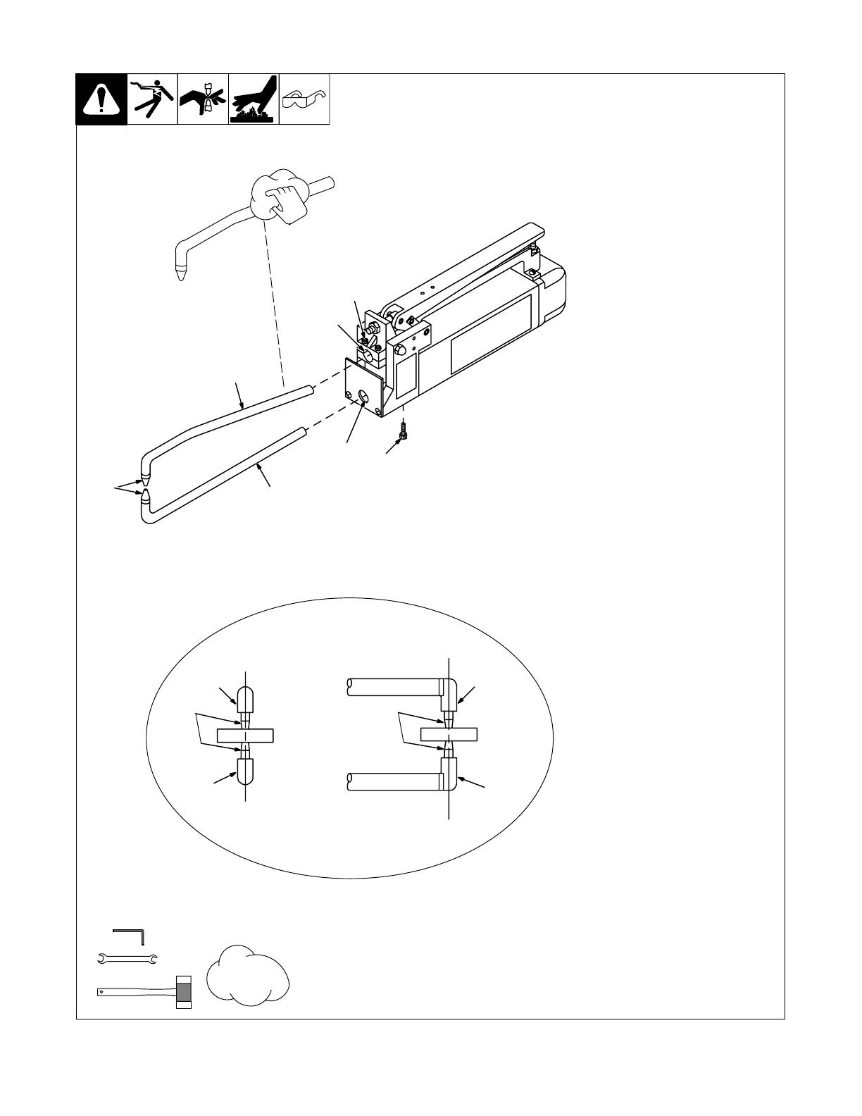
4-2. Installing Or Cleaning Tongs
ST-800 155-A / Ref. ST-800 154-A
Y Turn off and unplug welder.
. Be sure tong ends are clean
and not corroded before
installing. Clean tongs with fine
steel wool.
Bottom Tong:
1 Bottom Tong
2 Hole In Spatter Guard
3 Bottom Tong Securing Screws
(4)
Loosen the four screws. If needed,
use a rubber mallet to loosen tong.
Slide tong into bottom tong holder
as far as possible, and position so
that tip is pointing straight up.
Loosely tighten screws.
Top Tong:
4 Top Tong
5 Top Tong Holder/Pivot Casting
6 Top Tong Securing Screws (4)
Loosen the four screws. If needed
for removal, use a rubber mallet to
loosen tong.
Slide tong into pivot casting as far
as necessary, so that tip mates with
bottom tip when tongs are closed.
Loosely tighten screws.
7 Tips
Adjust tong positions to line up cen-
ters of tips as shown. Tighten
screws.
1
2
4
5
6
3
1
4
4
1
7
7
Tools Needed:
3/16 in
9/16 in
Front View Side View
Tong Alignment
7
Fine
Steel
Wool
Y OSHA and/or local codes may require addi-
tional guarding to suit the application.

OM-716 Page 10
4-3. Adjusting Tong And Hand Lever Pressure
Y Turn off and unplug welder.
Y Excessive tong pressure can dam-
age tips. Do not use tongs as a clamp
or vice to hold workpiece together. If
the two pieces of material to be
welded do not make good contact at
the point of the intended weld, clamp
material to provide good contact be-
tween surfaces.
. Tong pressure is adjustable, and must
be checked and/or set before operation.
Correct tong pressure is necessary to
create a quality weld and to prevent
damage to tips.
Too much tong pressure causes the
weld nugget to dimple and material to
splash out around the nugget area.
If tong pressure is too weak, parts are
loose when the tongs close, severe arc-
ing occurs between workpieces, and no
weld can be made.
1 Front Nut
2 Rear Nut
3 Pivot Casting
4 Hand Lever
5 Tongs
To increase tong pressure, loosen front nut.
The farther the front nut is turned out, the
greater the pressure on the tips when the
hand lever is closed. Turn the rear nut up to
the pivot casting to lock the position.
To decrease tong pressure, loosen the rear
nut and turn the front nut up to the pivot cast-
ing.
6 Machine Screw
The farther down the screw is turned, the far-
ther the hand lever will close. Adjustment of
this screw will determine if the tongs lock on
the material, or just pull up tight. Adjust screw
to allow lever to be raised easily after the
weld has been completed.
7 Hex Nut
To adjust pressure needed to push down
hand lever, turn the hex nuts located on each
side of the pivot casting.
Tools Needed:
1
2
3
4
5
6
7
Ref. ST-800 156
9/16, 11/16 in

OM-716 Page 11
4-4. Installing Handle
Y Turn off and unplug welder.
1 Wodden Handle
2 Handle Bolt
3 Brackets (41 And 41T Models Only)
Install handle onto the spot welder as shown
above. For 52, and 52T Models, install han-
dle onto either side as desired for either right-
hand or left-hand use.
Tools Needed:
Ref. ST-802 056-A
7/16, 3/8 in
MSW 52, And 52T Models
MSW 41 And 41T Models
2
1
3
1
2
1
2

OM-716 Page 12
4-5. Mounting Control Box
ST-800 233-A
Push-in slots are provided on rear
of box for wall mounting if desired.
The slots will fit over 1/4 inch hex-
head screws. To mount box, pro-
ceed as follows:
1 Control Box
2 Push-In Slots (Not Shown)
Use slots as template and install
screws at desired locations leaving
1/8 inch stickout.
Push rear slots firmly against screw
heads, and slide box down onto
screws.
1
2
OR
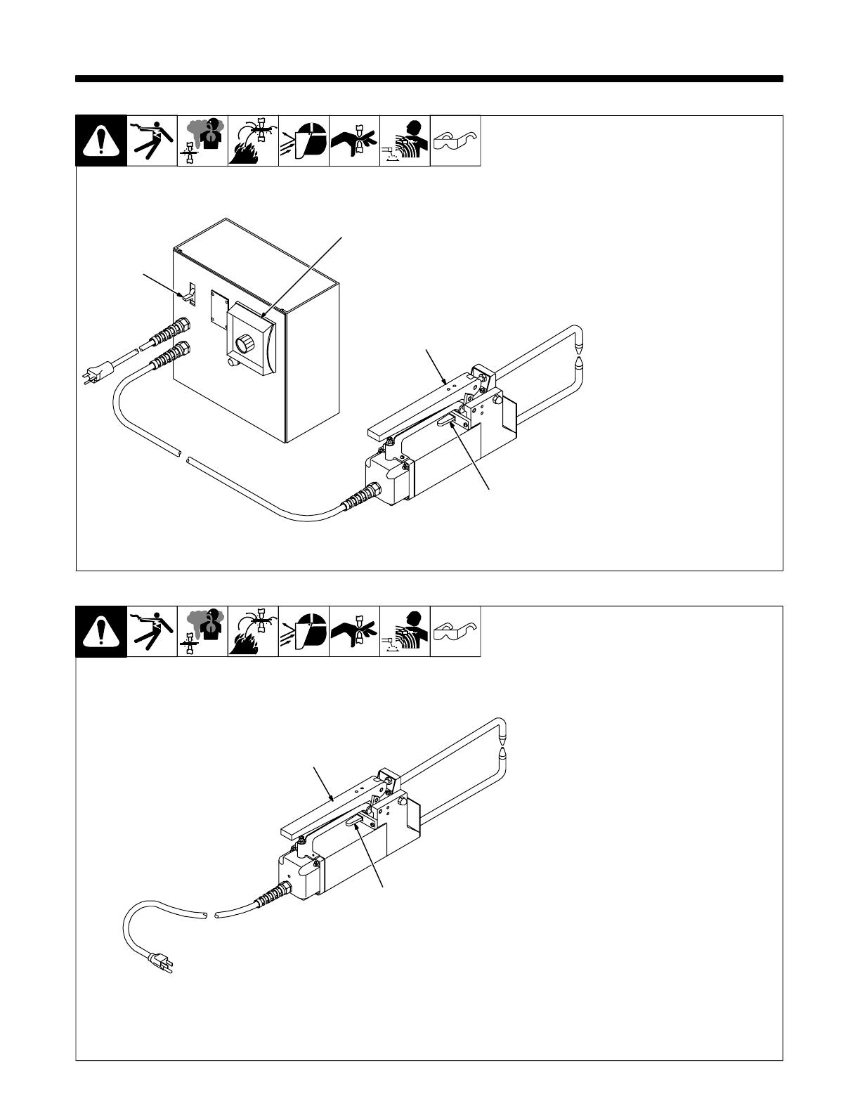
4-6. Connecting Input Power (T Models)
Ref. ST-800 233-A
Operate spot welder from a sepa-
rately fused or circuit breaker pro-
tected circuit, and use correct size
input conductors.
1 Rating Label (Not Visible As
Shown On Spot Welder)
2 Cord
3 Parallel Plug On 110 Volts AC
Models
4 Tandem Plug On 220 Volts
AC Models
Do not cut ground terminal off plug.
5 Grounded Receptacle
Connect plug to matching
grounded receptacle.
Model
Input Conductor
Size (AWG)
Fuse/Circuit Breaker
Size In Amperes
1.5 kVA 110 Volt
1.5 kVA 220 Volt
2.5 kVA 220 Volt
No. 10
No. 12
No. 10
30
15
30
2
3
4
5
1
OR
1

OM-716 Page 13
4-7. Connecting Input Power (Non-T Models)
Ref. ST-800 156
Y Input power supply wiring
and receptacle must meet
National Electrical Code and
all other code requirements.
Operate spot welder from a sepa-
rately fused or circuit breaker pro-
tected circuit, and use correct size
input conductors.
1 Rating Label
2 Cord
3 Parallel Plug On 110 Volts AC
Models
4 Tandem Plug On 220 Volts
AC Models
Do not cut ground terminal off plug.
5 Grounded Receptacle
Connect plug to matching
grounded receptacle.
12
3
Or
4
5
Model
Input Conductor
Size (AWG)
Fuse/Circuit Breaker
Size In Amperes
1.5 kVA 110 Volt
2.5 kVA 220 Volt
No. 10
No. 10
30
30
OM-716 Page 14
SECTION 5 − OPERATION
5-1. Controls (T Models)
ST-146 013-B
1 Spot Weld Timer And Pilot
Light
Weld time adjusts from 0 to 5
seconds. The pilot light turns on
when the weld cycle begins and off
when the cycle ends.
2 Hand Lever
Use lever to open and close tongs.
Close the hand lever during the
welding process to compress the
material between the tips. To adjust
tong pressure, see Section 4-3.
3 Start Switch
Move start switch sideways in ei-
ther direction to start weld cycle.
When weld cycle time ends, or the
start switch is released, weld output
stops, and the timer resets for
another weld cycle.
4 Power Switch
2
3
1
4
5-2. Controls (Non-T Models)
ST-145 104-A
1 Hand Lever
Use lever to open and close tongs.
Close the hand lever during the
welding process to compress the
material between the tips. To adjust
tong pressure, see Section 4-3.
2 Start Switch
Use switch to turn weld current On
and Off. Move switch sideways in
either direction to start weld current.
Release switch to stop weld cur-
rent.
1
2
OM-716 Page 15
SECTION 6 − MAINTENANCE AND TROUBLESHOOTING
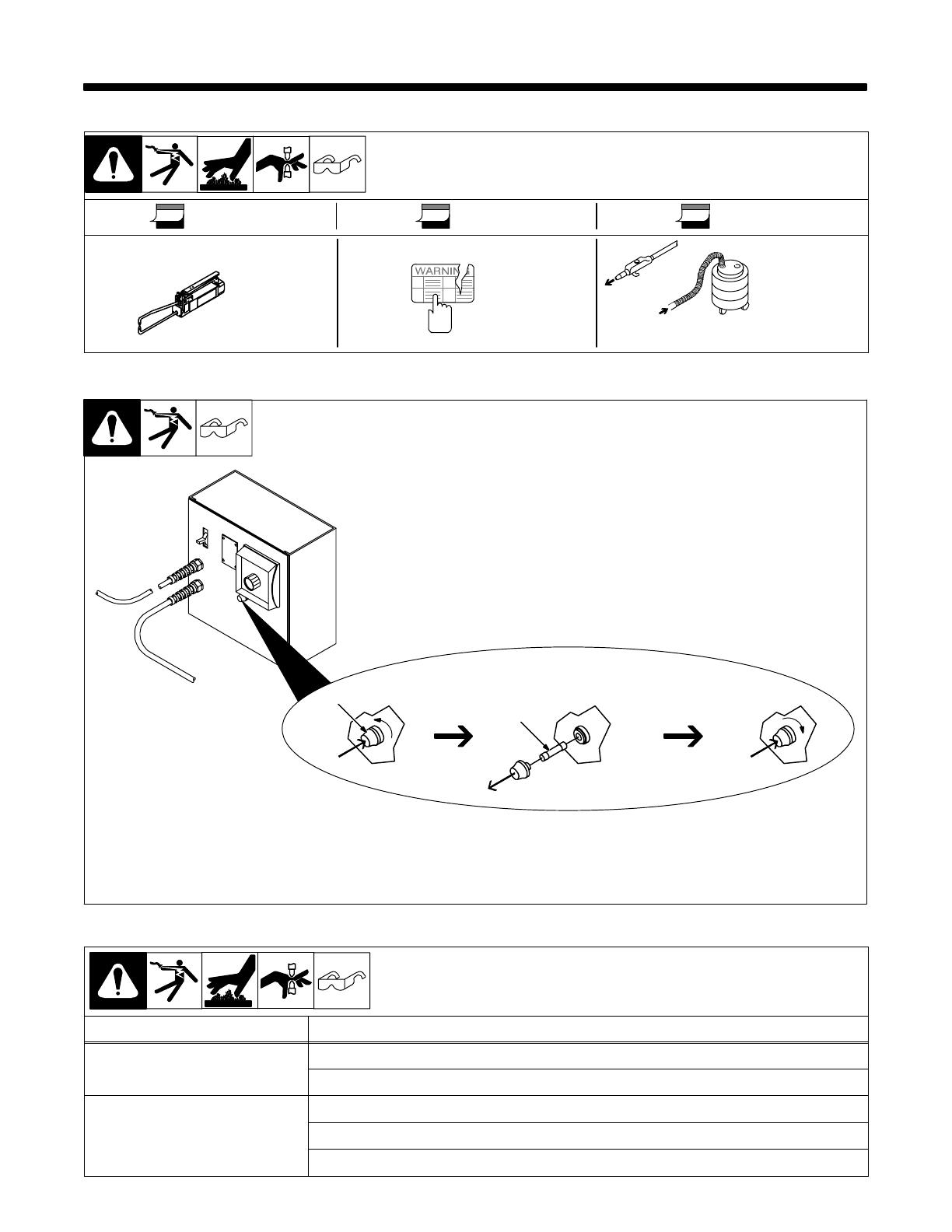
6-1. Routine Maintenance
Y Disconnect power before maintaining.
Every Use 3 Months 6 Months
Inspect
Tips
Replace
Unreadable
Labels
Blow Off
Or
Vacuum
Unit
During Heavy Service,
Clean Monthly
OR
6-2. Overload Protection For 220 Volts Model
Ref. ST-800 233-A / Ref. ST-800 185-A
Y Turn Off unit and disconnect
input power.
If fuse opens, unit shuts down. To
replace fuse, proceed as follows:
1 Fuse Holder Cover
2 Fuse F1 (See Parts List)
1
2
6-3. Troubleshooting
Trouble Remedy
No weld output. Check line fuses, and replace if necessary.
For 220 V models, check fuse F1, and replace if necessary (see Section 6-2).
Low weld output. Dress or replace tips (see Section 4-1).
Check tip threads. Replace tips if necessary (see Section 4-1).
Remove and clean tongs (see Section 4-2).
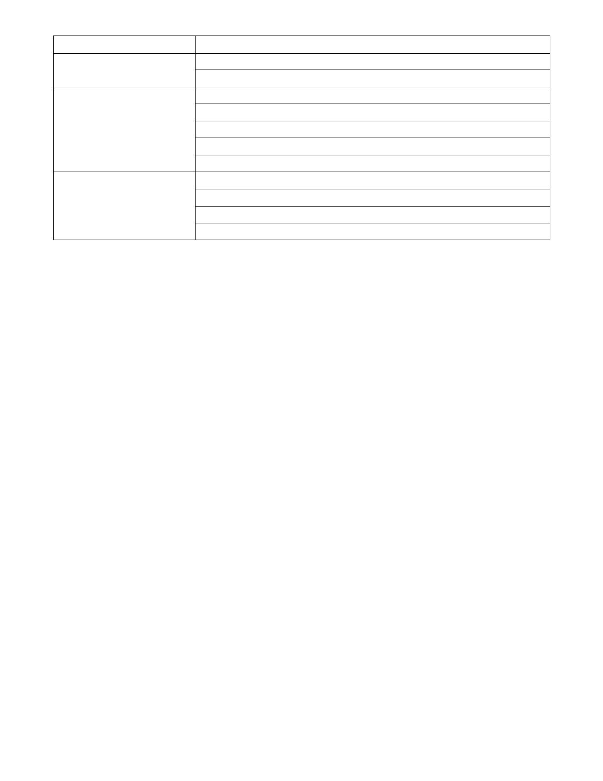
OM-716 Page 16
Trouble Remedy
Clean ends of tongs and tong holders (see Section 4-2).
Check power switch (T models only) and/or start switch. Replace if necessary.
Longer than normal weld time required. Dress or replace tips (see Section 4-1).
Clean workpieces.
Adjust tong pressure (see Section 4-3).
Clean ends of tongs and tong holders (see Section 4-2).
Check input line voltage.
Burn through at point of weld. Shorten weld time (see Section 5-1).
Adjust tong pressure (see Section 4-3).
Dress or replace tips (see Section 4-1).
Realign tips (see Section 4-2).
/