Peavey A-A-AC8 Owner's manual
- Category
- Audio amplifiers
- Type
- Owner's manual
This manual is also suitable for
Page is loading ...

2
Intended to alert the user to the presence of uninsulated "dangerous voltage" within the product's enclosure
that may be of sufficient magnitude to constitute a risk of electric shock to persons.
Intended to alert the user of the presence of important operating and maintenance (servicing) instructions in the
literature accompanying the product.
CAUTION: Risk of electrical shock – DO NOT OPEN!
CAUTION: To reduce the risk of electric shock, do not remove cover. No user serviceable parts inside. Refer servicing to
qualified service personnel.
WARNING: To prevent electrical shock or fire hazard, do not expose this appliance to rain or moisture. Before using this
appliance, read the operating guide for further warnings.
Este símbolo tiene el propósito de alertar al usuario de la presencia de "(voltaje) peligroso" que no tiene
aislamiento dentro de la caja del producto que puede tener una magnitud suficiente como para constituir riesgo de
corrientazo.
Este símbolo tiene el propósito de alertar al usario de la presencia de instruccones importantes sobre la operación
y mantenimiento en la literatura que viene con el producto.
PRECAUCION: Riesgo de corrientazo – No abra.
PRECAUCION: Para disminuír el riesgo de corrientazo, no abra la cubierta. No hay piezas adentro que el usario pueda
reparar. Deje todo mantenimiento a los técnicos calificados.
ADVERTENCIA: Para evitar corrientazos o peligro de incendio, no deje expuesto a la lluvia o humedad este aparato
Antes de usar este aparato, lea más advertencias en la guía de operación.
Ce symbole est utilisé pur indiquer à l'utilisateur la présence à l'intérieur de ce produit de tension non-isolée
dangereuse pouvant être d'intensité suffisante pour constituer un risque de choc électrique.
Ce symbole est utilisé pour indiquer à l'utilisateur qu'il ou qu'elle trouvera d'importantes instructions sur
l'utilisation et l'entretien (service) de l'appareil dans la littérature accompagnant le produit.
ATTENTION: Risques de choc électrique – NE PAS OUVRIR!
ATTENTION: Afin de réduire le risque de choc électrique, ne pas enlever le couvercle. Il ne se trouve à l'intérieur
aucune pièce pouvant être réparée par l'utilisateur. Confier l'entretien à un personnel qualifié.
AVERTISSEMENT: Afin de prévenir les risques de décharge électrique ou de feu, n'exposez pas cet appareil à la pluie
ou à l'humidité. Avant d'utiliser cet appareil, lisez les avertissements supplémentaires situés dans le guide.
Dieses Symbol soll den Anwender vor unisolierten gefährlichen Spannungen innerhalb des Gehäuses warnen, die
von Ausreichender Stärke sind, um einen elektrischen Schlag verursachen zu können.
Dieses Symbol soll den Benutzer auf wichtige Instruktionen in der Bedienungsanleitung aufmerksam machen, die
Handhabung und Wartung des Produkts betreffen.
VORSICHT: Risiko – Elektrischer Schlag! Nicht öffnen!
VORSICHT: Um das Risiko eines elektrischen Schlages zu vermeiden, nicht die Abdeckung enfernen. Es befinden sich
keine Teile darin, die vom Anwender repariert werden könnten. Reparaturen nur von qualifiziertem Fachpersonal
durchführen lassen.
ACHTUNG: Um einen elektrischen Schlag oder Feuergefahr zu vermeiden, sollte dieses Gerät nicht dem Regen oder
Feuchtigkeit ausgesetzt werden. Vor Inbetriebnahme unbedingt die Bedienungsanleitung lesen.

3
E N G L I S H
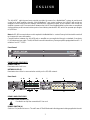
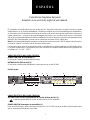
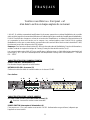
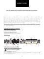
FRONT PANEL FEATURES
POWER LED (1)
Illuminates when unit is on.
NETWORK LED (2)
Illuminates when there is communication activity on the RS-485 network.
Rear Panel:
REAR PANEL FEATURES
AC LINE CORD SOCKET (3)
Provided to accept the removable AC line cord.
POWER SWITCH (4)
Switch to “On” position to turn on. The red Power LED will illuminate indicating power is being supplied to the unit.
4
3
5b
5c
5a 5e
5d
67
8
9
12
The A/A-AC8™ eight-channel amp controller provides the means for a MediaMatrix
®
system to monitor and
control up to eight amplifier channels. With MediaMatrix
®
amp control software, the A/A-AC8 will monitor an
amplifier’s load current and load voltage, determine the operational status of the amplifier, and control the
amplifier’s power on/off. Communications between the A/A-AC8 and the MediaMatrix system are accomplished
via a proprietary serial communications protocol over industry standard RS-485, which can operate up to lengths
of 4,000 feet.
Note: An RS-485 communications card is required in the MediaMatrix—contact Peavey Architectural Acoustics®
tech support for more information.
Communications between the A/A-AC8 and an amplifier are accomplished through a standard 8-conductor
RJ-45 telephone-type cable. The A/A-AC8 will communicate with any Peavey amplifier equipped with an ACI
™
-2
module or an IDC
™
150TII.
Front Panel:

4
2X16 PHOENIX-TYPE CONNECTOR (5)
a. RS-485 Network Communication Connections.
b. Monitor 1 and Monitor 2 Differential Audio inputs.
c. Monitor 1 and Monitor 2 Differential Audio outputs.
d. Parallel Command Interface (future use).
e. Analog amplifier Voltage, Current, and Status outputs (future use).
UNIT ID 8-PIN DIP (6)
Defines the unit location on the RS-485 network.
MONITOR 1 & MONITOR 2 INPUT TRIM POTS (7)
Determine the level of the Monitor Input signals that get mixed to the Monitor Outputs.
CHANNEL MONITOR TRIM POTS (8)
Determine the level of the amplifier signals that get mixed to the Monitor Outputs.
AMPLIFIER INPUTS (9)
RJ-45 connector inputs from an amplifier’s ACI-2 module.
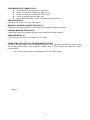
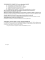
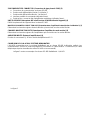
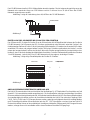
CONNECTING THE A/A-AC8 TO THE MEDIAMATRIX SYSTEM
The A/A-AC8 communicates with the MediaMatrix system via an RS-485 multi-drop network. Communications
are half-duplex and require a two-conductor, shielded cable (24 AWG twisted pair telephone cable is
recommended).
Figure 1 shows an example of a MediaMatrix-A/A-AC8 RS-485 network.
figure 1

5
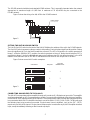
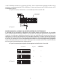
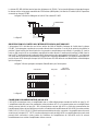
The RS-485 network should be terminated with 120Ω resistors. This is especially important when the network
approaches its maximum length of 4,000 feet. A maximum of 32 A/A-AC8s may be connected to the
RS-485 network.
Figure 2 shows the wiring of an A/A-AC8 to the RS-485 network.
(on back panel of AC8)
+
NET
_
NET
+
_
+
_
_
+
Phoenix Connector
V
_
I
_
M
_
V
_
I
_
M
_
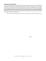
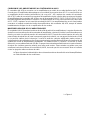
SETTING THE UNIT ID 8-PIN DIP SWITCH
The Unit ID 8-pin DIP switch on the back of the A/A-AC8 defines the address of the unit in the RS-485 network.
The 8-pin DIP switch represents a binary number, with position 1 being the least significant bit, position 5 being
the most significant bit. (Only the first five switches are used.) The UP or ON position of a switch represents a
binary 1, while the DOWN or OFF position of a switch represents a binary 0. Notice that all switches OFF is
equivalent to binary 0, but in the MediaMatrix amp control software view file, this defines location 1 in the AC8
Network. Note that each A/A-AC8 in the RS-485 Network must have its own unique unit ID location.
Figure 3 shows some Unit ID switch examples.
Amp Control
MediaMatrix Unit ID
1
2
3
Binary Value
0
1
2
Switch Position
12345678
12345678
12345678
O
N
O
N
O
N
CONNECTING AN AMPLIFIER TO THE A/A-AC8
The A/A-AC8 communicates with an amplifier through an 8-conductor RJ-45 telephone-type cable. The amplifier
must be equipped with an ACI-2 communications module. Communication with a dual channel (stereo) amplifier,
such as the IA
™
400, requires two A/A-AC8 channels. The communication cable from the dual channel amp must
be connected at the A/A-AC8’s Amplifier Interface to one of the DUAL CH1/2, CH3/4, CH5/6, CH7/8 inputs, and
the following input must remain unconnected. Single-channel (mono) amplifiers, such as the IDC
™
150TII,
require only one A/A-AC8 channel. Single-channel amps may be connected to any A/A-AC8 Amplifier Interface
input, except immediately following a dual channel amp input.
figure 2
figure 3

6
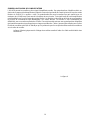
AMPLIFIER AUDIO MONITORING
The A/A-AC8 allows monitoring of an amplifier’s audio signal. There are trim pots above each amplifier input
which adjust the level of the amp’s audio signal that gets mixed to the A/A-AC8's Monitor Outputs. The channel
trim pot’s 12 o’clock position corresponds to unity gain, with a maximum of +14 dB gain when fully clockwise.
Any amp channel’s audio signal can be routed to either of the two Monitor Outputs. The routing is accomplished
within the MediaMatrix amp control software view. The Monitor 1 and Monitor 2 outputs are differentially driven,
with a maximum output of +22 dBu. External audio inputs with trim pots (maximum unity gain) are provided for
each Monitor channel. These may be used to chain A/A-AC8 monitor busses so that only one set of monitor audio
cables need be routed to the control room.
Figure 4 shows a typical Amp Control audio monitor wiring using two-conductor, shielded audio cable.
Note: Windows
®
is a registered trademark of the Microsoft Corporation.
figure 4
Page is loading ...
Page is loading ...
Page is loading ...
Page is loading ...
Page is loading ...
Page is loading ...
Page is loading ...
Page is loading ...
Page is loading ...
Page is loading ...
Page is loading ...
Page is loading ...

19
LIMITED WARRANTY
Peavey Electronics Corporation warrants to the original purchaser of this new Architectural Acoustics product that
it is free from defects in material and workmanship. If within one (1) year from date of purchase a properly installed
product proves to be defective and Peavey is notified, Peavey will repair or replace it at no charge. (Note: Batteries
and patch cords not covered.) “Original purchaser” means the customer for whom the product is originally installed.
Damage resulting from improper installation, interconnection of a unit or system of another manufacturer, accident
or unreasonable use, neglect or any other cause not arising from defects in material and workmanship is not covered
by this warranty. The warranty is valid only as to products purchased and installed in the United States and Canada.
THIS LIMITED WARRANTY IS IN LIEU OF ANY AND ALL WARRANTIES, EXPRESSED OR IMPLIED,
INCLUDING THE IMPLIED WARRANTIES OF MERCHANTABILITY AND FITNESS FOR A PARTICULAR USE.
UNDER NO CIRCUMSTANCES WILL PEAVEY BE LIABLE FOR ANY LOST PROFITS, LOST SAVINGS, INCIDEN-
TAL DAMAGES OR CONSEQUENTIAL DAMAGES ARISING OUT OF THE USE OR INABILITY TO USE THE
PRODUCT, EVEN IF PEAVEY HAS BEEN ADVISED OF THE POSSIBILITY OF SUCH DAMAGE. THIS LIMITED
WARRANTY IS THE ONLY EXPRESSED WARRANTY ON THIS PRODUCT, AND NO OTHER STATEMENT,
REPRESENTATION, WARRANTY, OR AGREEMENT BY ANY PERSON SHALL BE VALID OR BINDING UPON
PEAVEY.
Peavey’s liability to the original purchaser for damages for any cause whatsoever and regardless of the form of
action is limited to the actual damages up to the greater of Five Hundred Dollars ($500) or an amount equal to the
purchase price of the product that caused the damage or that is the subject of or is directly related to the cause of action.
This limitation of liability will not apply to claims for personal injury or damage to real property or tangible personal
property allegedly caused by Peavey’s negligence. For information on service under this warranty, call a Peavey
customer service representative at (601) 483-5376.
SPECIFICATIONS
Dimensions & Weight: Power Consumption:
1.75" H x 19" W x 11.25" D (excluding connectors) Domestic: 25 watts, 60 Hz, 120VAC
8.2 pounds Export: 25 watts, 50/60 Hz, 230VAC

20
TM
®
Features and specifications subject to change without notice.
A Division of Peavey Electronics Corporation
711 A Street / Meridian, MS 39301 / U.S.A. / (601) 483-5376 / Fax (601) 486-1154
©1996 #80300389 Printed in U.S.A. 8/96
®
ARCHITECTURAL ACOUSTICS
®
IMPORTANT SAFETY INSTRUCTIONS
WARNING: When using electric products, basic cautions should always be followed, including the following.
1. Read all safety and operating instructions before using this product.
2. All safety and operating instructions should be retained for future reference.
3. Obey all cautions in the operating instructions and on the back of the unit.
4. All operating instructions should be followed.
5. This product should not be used near water, i.e., a bathtub, sink, swimming pool, wet basement, etc.
6. This product should be located so that its position does not interfere with its proper ventilation. It should not be placed flat against a
wall or placed in a built-in enclosure that will impede the flow of cooling air.
7. This product should not be placed near a source of heat such as a stove, radiator, or another heat producing amplifier.
8. Connect only to a power supply of the type marked on the unit adjacent to the power supply cord.
9. Never break off the ground pin on the power supply cord. For more information on grounding, write for our free booklet “Shock
Hazard and Grounding.”
10. Power supply cords should always be handled carefully. Never walk or place equipment on power supply cords. Periodically check
cords for cuts or signs of stress, especially at the plug and the point where the cord exits the unit.
11. The power supply cord should be unplugged when the unit is to be unused for long periods of time.
12. If this product is to be mounted in an equipment rack, rear support should be provided.
13. Metal parts can be cleaned with a damp rag. The vinyl covering used on some units can be cleaned with a damp rag or an ammonia-
based household cleaner if necessary. Disconnect unit from power supply before cleaning.
14. Care should be taken so that objects do not fall and liquids are not spilled into the unit through the ventilation holes or any other
openings.
15. This unit should be checked by a qualified service technician if:
a. The power supply cord or plug has been damaged.
b. Anything has fallen or been spilled into the unit.
c. The unit does not operate correctly.
d. The unit has been dropped or the enclosure damaged.
16. The user should not attempt to service this equipment. All service work should be done by a qualified service technician.
17. This product should be used only with a cart or stand that is recommended by Peavey Electronics.
18. Exposure to extremely high noise levels may cause a permanent hearing loss. Individuals vary considerably in susceptibility to noise
induced hearing loss, but nearly everyone will lose some hearing if exposed to sufficiently intense noise for a sufficient time.
The U.S. Government’s Occupational Safety and Health Administration (OSHA) has specified the following permissible noise level
exposures.
Duration Per Day In Hours Sound Level dBA, Slow Response
890
692
495
397
2 100
1 1/2 102
1 105
1/2 110
1/4 or less 115
According to OSHA, any exposure in excess of the above permissible limits could result in some hearing loss. Ear plugs or protectors in
the ear canals or over the ears must be worn when operating this amplification system in order to prevent a permanent hearing loss if
exposure is in excess of the limits as set forth above. To ensure against potentially dangerous exposure to high sound pressure levels, it is
recommended that all persons exposed to equipment capable of producing high sound pressure levels such as this amplification system be
protected by hearing protectors while this unit is in operation.
SAVE THESE INSTRUCTIONS!
-
 1
1
-
 2
2
-
 3
3
-
 4
4
-
 5
5
-
 6
6
-
 7
7
-
 8
8
-
 9
9
-
 10
10
-
 11
11
-
 12
12
-
 13
13
-
 14
14
-
 15
15
-
 16
16
-
 17
17
-
 18
18
-
 19
19
-
 20
20


Peavey A-A-AC8 Owner's manual
- Category
- Audio amplifiers
- Type
- Owner's manual
- This manual is also suitable for
Ask a question and I''ll find the answer in the document
Finding information in a document is now easier with AI
in other languages
- français: Peavey A-A-AC8 Le manuel du propriétaire
- español: Peavey A-A-AC8 El manual del propietario
- Deutsch: Peavey A-A-AC8 Bedienungsanleitung
Related papers
-
Peavey IDC 150T II User manual
-
-
-
-
-
-
-
-
-
 Architectural Acoustics MMA81502 User manual

Other documents
-
Emerson AC8 User manual
-
MediaMatrix nControl User manual
-
Tristar MW-2905 Owner's manual
-
Panasonic DMW-DCC12 User manual
-
Yamaha RM2408 Owner's manual
-
Tenda AC8 User guide
-
EverFocus Indoor Pendent Dome Camera EPD200 User manual
-
Intermec AC8 User manual
-
Intermec IP30 Instructions Manual
-