
Defi nitions: Safety Guidelines
The definitions below describe the level of severity for each signal word. Please read the
manual and pay attention to these symbols.
DANGER: Indicates an imminently hazardous situation which, if not avoided, will
result in death or serious injury.
WARNING: Indicates a potentially hazardous situation which, if not avoided, could
result in death or serious injury.
CAUTION: Indicates a potentially hazardous situation which, if not avoided, may result
in minor or moderate injury.
NOTICE: Indicates a practice not related to personal injury which, if not avoided, may
result in property damage.
IF YOU HAVE ANY QUESTIONS OR COMMENTS ABOUT THIS OR ANY DEWALT TOOL, CALL
US TOLL FREE AT: 1-800-4-D
EWALT (1-800-433-9258).
WARNING: To reduce the risk of injury, read the instruction manual.
General Power Tool Safety Warnings
WARNING! Read all safety warnings and all instructions. Failure to follow the
warnings and instructions may result in electric shock, fire and/or serious injury.
SAVE ALL WARNINGS AND INSTRUCTIONS
FOR FUTURE REFERENCE
The term “power tool” in the warnings refers to your mains-operated (corded) power tool or
battery-operated (cordless) power tool.
1) WORK AREA SAFETY
a) Keep work area clean and well lit. Cluttered or dark areas invite accidents.
b) Do not operate power tools in explosive atmospheres, such as in the presence
of flammable liquids, gases or dust. Power tools create sparks which may ignite the
dust or fumes.
c) Keep children and bystanders away while operating a power tool. Distractions can
cause you to lose control.
2) ELECTRICAL SAFETY
a) Power tool plugs must match the outlet. Never modify the plug in any way. Do
not use any adapter plugs with earthed (grounded) power tools. Unmodified plugs
and matching outlets will reduce risk of electric shock.
b) Avoid body contact with earthed or grounded surfaces such as pipes, radiators,
ranges and refrigerators. There is an increased risk of electric shock if your body is
earthed or grounded.
c) Do not expose power tools to rain or wet conditions. Water entering a power tool
will increase the risk of electric shock.
d) Do not abuse the cord. Never use the cord for carrying, pulling or unplugging
the power tool. Keep cord away from heat, oil, sharp edges or moving parts.
Damaged or entangled cords increase the risk of electric shock.
e) When operating a power tool outdoors, use an extension cord suitable for
outdoor use. Use of a cord suitable for outdoor use reduces the risk of electric shock.
f) If operating a power tool in a damp location is unavoidable, use a ground fault
circuit interrupter (GFCI) protected supply. Use of a GFCI reduces the risk of electric
shock.
3) PERSONAL SAFETY
a) Stay alert, watch what you are doing and use common sense when operating a
power tool. Do not use a power tool while you are tired or under the influence
of drugs, alcohol or medication. A moment of inattention while operating power tools
may result in serious personal injury.
b) Use personal protective equipment. Always wear eye protection. Protective
equipment such as dust mask, non-skid safety shoes, hard hat, or hearing protection
used for appropriate conditions will reduce personal injuries.
c) Prevent unintentional starting. Ensure the switch is in the off position before
connecting to power source and/or battery pack, picking up or carrying the tool.
Carrying power tools with your finger on the switch or energizing power tools that have
the switch on invites accidents.
d) Remove any adjusting key or wrench before turning the power tool on. A wrench
or a key left attached to a rotating part of the power tool may result in personal injury.
e) Do not overreach. Keep proper footing and balance at all times. This enables better
control of the power tool in unexpected situations.
f) Dress properly. Do not wear loose clothing or jewelry. Keep your hair, clothing
and gloves away from moving parts. Loose clothes, jewelry or long hair can be caught
in moving parts.
g) If devices are provided for the connection of dust extraction and collection
facilities, ensure these are connected and properly used. Use of dust collection can
reduce dust-related hazards.
4) POWER TOOL USE AND CARE
a) Do not force the power tool. Use the correct power tool for your application. The
correct power tool will do the job better and safer at the rate for which it was designed.
b) Do not use the power tool if the switch does not turn it on and off. Any power tool
that cannot be controlled with the switch is dangerous and must be repaired.
c) Disconnect the plug from the power source and/or the battery pack from the
power tool before making any adjustments, changing accessories, or storing
power tools. Such preventive safety measures reduce the risk of starting the power tool
accidentally.
d) Store idle power tools out of the reach of children and do not allow persons
unfamiliar with the power tool or these instructions to operate the power tool.
Power tools are dangerous in the hands of untrained users.
e) Maintain power tools. Check for misalignment or binding of moving parts,
breakage of parts and any other condition that may affect the power tool’s
operation. If damaged, have the power tool repaired before use. Many accidents
are caused by poorly maintained power tools.
f) Keep cutting tools sharp and clean. Properly maintained cutting tools with sharp
cutting edges are less likely to bind and are easier to control.
g)
Use the power tool, accessories and tool bits, etc. in accordance with these
instructions, taking into account the working conditions and the work to be
performed. Use of the power tool for operations different from those intended could
result in a hazardous situation.
5) SERVICE
a) Have your power tool serviced by a qualified repair person using only identical
replacement parts. This will ensure that the safety of the power tool is maintained.
Additional Safety Rules for Routers
• Hold power tool by insulated gripping surfaces because the cutter may contact its
own cord. Cutting a “live” wire may make exposed metal parts of the tool “live” and shock
the operator.
• Use clamps or another practical way to secure and support the workpiece to a
stable platform. Holding the work by your hand or against the body leaves it unstable and
may lead to loss of control.
• Metal cutting with router: If using router for metal cutting, clean out tool often.
Metal dust and chips often accumulate on interior surfaces and could create a risk of serious
injury, electrical shock or death.
• Never run the motor unit when it is not inserted in one of the router bases. The motor
is not designed to be handheld.
• Keep handles dry, clean and free from oil and grease. This will enable better control of
the tool.
• Maintain a firm grip with both hands on the tool to resist starting torque. Maintain a
firm grip on the tool at all times while operating.
INSTRUCTION MANUAL
GUIDE D’UTILISATION
MANUAL DE INSTRUCCIONES
DW616, DW618
Router System
Système de toupie
Sistema de rebajadora
INSTRUCTIVO DE OPERACIÓN, CENTROS DE SERVICIO Y
PÓLIZA DE GARANTÍA.
ADVERTENCIA: LÉASE ESTE
INSTRUCTIVO ANTES DE USAR EL PRODUCTO.
DEWALT Industrial Tool Co., 701 East Joppa Road, Towson, MD 21286
(APR14) Part No. N384518 DW616, DW618 Copyright © 2003, 2005, 2012, 2014 D
EWALT
The following are trademarks for one or more DEWALT power tools: the yellow and black color scheme, the “D” shaped
air intake grill, the array of pyramids on the handgrip, the kit box configuration, and the array of lozenge-shaped humps on
the surface of the tool.
• Keep hands away from cutting area above and below the base. Never reach under
the workpiece for any reason. Keep the router base firmly in contact with the workpiece
when cutting.
• Never touch the bit immediately after use. It may be extremely hot.
• Be sure that the motor has stopped completely before you lay the router down. If
the bit is still spinning when the tool is laid down, it could cause injury or damage.
• Be sure that the router bit is clear of the workpiece before starting the motor. If the
bit is in contact with the workpiece when the motor starts, it could make the router jump,
causing damage or injury.
• Always follow the bit manufacturer’s speed recommendations as some bit designs
require specific speeds for safety or performance. If you are unsure of the proper
speed or are experiencing any type of problem, contact the bit manufacturer.
• Do not use router bits with a diameter in excess of 2-1/2" (63 mm) in this tool.
• Do not hand-hold the router in an upside-down or horizontal position. The motor can
separate from the base if not properly attached according to the instructions.
• Before starting the motor, check to see that the cord will not snag or impede the
routing operation.
• Keep cutting pressure constant. Do not overload motor.
• Provide clearance under workpiece for bit when through-cutting.
• Do not press spindle lock button while the motor is running. Doing so can damage
the spindle lock.
• Always make sure the work surface is free from nails and other foreign objects.
Cutting into a nail can cause the bit and the tool to jump.
• Air vents often cover moving parts and should be avoided. Loose clothes, jewelry or
long hair can be caught in moving parts.
• An extension cord must have adequate wire size (AWG or American Wire Gauge)
for safety. The smaller the gauge number of the wire, the greater the capacity of the cable,
that is 16 gauge has more capacity than 18 gauge. An undersized cord will cause a drop in
line voltage resulting in loss of power and overheating. When using more than one extension
to make up the total length, be sure each individual extension contains at least the minimum
wire size. The following table shows the correct size to use depending on cord length and
nameplate ampere rating. If in doubt, use the next heavier gauge. The smaller the gauge
number, the heavier the cord.
Minimum Gauge for Cord Sets
Ampere Rating
Volts Total Length of Cord in Feet (meters)
120V 25 (7.6) 50 (15.2) 100 (30.5) 150 (45.7)
240V 50 (15.2) 100 (30.5) 200 (61.0) 300 (91.4)
More
Than
Not More
Than
AWG
0 6 18 16 16 14
610 18161412
10 12 16 16 14 12
12 16 14 12 Not Recommended
WARNING: ALWAYS use safety glasses. Everyday eyeglasses are NOT safety glasses.
Also use face or dust mask if cutting operation is dusty. ALWAYS WEAR CERTIFIED SAFETY
EQUIPMENT:
• ANSI Z87.1 eye protection (CAN/CSA Z94.3),
• ANSI S12.6 (S3.19) hearing protection,
• NIOSH/OSHA/MSHA respiratory protection.
WARNING: Some dust created by power sanding, sawing, grinding, drilling, and other
construction activities contains chemicals known to the State of California to cause cancer, birth
defects or other reproductive harm. Some examples of these chemicals are:
• lead from lead-based paints,
• crystalline silica from bricks and cement and other masonry products, and
• arsenic and chromium from chemically-treated lumber.
Your risk from these exposures varies, depending on how often you do this type of work.
To reduce your exposure to these chemicals: work in a well ventilated area, and work with
approved safety equipment, such as those dust masks that are specially designed to filter out
microscopic particles.
• Avoid prolonged contact with dust from power sanding, sawing, grinding, drilling,
and other construction activities. Wear protective clothing and wash exposed areas
with soap and water. Allowing dust to get into your mouth, eyes, or lay on the skin may
promote absorption of harmful chemicals.
WARNING: Use of this tool can generate and/or disperse dust, which may cause serious and
permanent respiratory or other injury. Always use NIOSH/OSHA approved respiratory protection
appropriate for the dust exposure. Direct particles away from face and body.
WARNING: Always wear proper personal hearing protection that conforms to ANSI
S12.6 (S3.19) during use. Under some conditions and duration of use, noise from this product
may contribute to hearing loss.
• The label on your tool may include the following symbols. The symbols and their definitions
are as follows
V .....................volts A .........................amperes
Hz ...................hertz W ........................watts
min .................minutes
or AC .............alternating current
or DC .....direct current or AC/DC......alternating or direct current
...................Class I Construction
n
o .......................no load speed
.......................
(grounded) n .........................rated speed
................... Class II Construction .......................earthing terminal
(double insulated)
........................safety alert symbol
…/min ............per minute BPM ...................beats per minute
IPM .................impacts per minute RPM ...................revolutions per minute
SPM ...............strokes per minute sfpm ...................surface feet per minute
SAVE THESE INSTRUCTIONS FOR FUTURE USE
Motor
Be sure your power supply agrees with the nameplate marking. Voltage decrease of more than
10% will cause loss of power and overheating. D
EWALT tools are factory tested; if this tool does
not operate, check power supply.
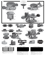
COMPONENTS (Fig. 1)
WARNING: Never modify the power tool or any part of it. Damage or personal injury could
result.
A. Quick release latch
B. Depth adjustment ring
C. Adjustable scale
D. Locking lever
E. Knob handle
F. Subbase
G. Speed dial (DW618 only)
H. Guide pin groove
I. Spindle lock button (DW618 only)
J. Collet nut
K. Toggle switch
L. Detachable cordset
M. Holes for universal edge guide
N. D-handle trigger switch
O. Trigger lock button
P. Turret stop
Q. Depth adjustment rod
R. Plunge lock lever
S. Dust shroud
T. Dust cap
U. D-Handle
INTENDED USE
This heavy-duty router is designed for professional routing applications.
DO NOT use under wet conditions or in presence of flammable liquids or gases.
This is a professional power tool. DO NOT let children come into contact with the tool.
Supervision is required when inexperienced operators use this tool.
Switch (Fig. 1)
To turn the tool on, push the toggle switch (K) to the ON position indicated on the tool. To turn
the tool off, push the toggle switch to the OFF position indicated on the tool.
Detachable Cord Set (Fig. 1A)
WARNING: To reduce the risk of injury, turn unit off and disconnect it from power
source before installing and removing cord set from motor or D-handle base. Before
connecting cord set to power source, ensure the toggle switch (K) and the D-handle trigger
switch (N) are in the OFF position. An accidental start-up can cause injury.
Insert the detachable cordset plug so that the key (W) is aligned with the notch (V) in the
socket. Turn the plug clockwise one quarter turn to lock.
OPERATION
WARNING: To reduce the risk of injury, turn unit off and disconnect it from power
source before installing and removing accessories, before adjusting or when making
repairs. An accidental start-up can cause injury.
WARNING: Before connecting cord set to power source, ensure the toggle switch
(K) and the D-handle trigger switch (N) are in the OFF position. An accidental start-up
can cause injury.
WARNING: Before starting the tool, clear the work area of all foreign objects. Check to see
that the cord will not snag or impede the routing operation. Also keep firm grip on tool to resist
starting torque.
General for All Bases
LOCKING LEVER ADJUSTMENT (FIG. 4)
You should be able to clamp the locking lever without excessive force. Excessive force may
damage the base.
You should not be able to move the motor in the base when the locking lever is clamped. To
adjust the locking lever’s clamping force, open the locking lever (D) and turn the nut (Y) in small
increments. Turning the nut clockwise tightens the lever while turning the nut counterclockwise
loosens the lever.
CENTERING THE SUBBASE (FIG. 5)
If you need to adjust, change, or replace the subbase, a centering tool (DNP617–sold separately)
is recommended (refer to Accessories). The centering tool consists of a cone and a pin.
To adjust the subbase, follow the steps below
1. Loosen but do not remove the subbase screws so that the subbase can move freely.
2. Insert the pin into the collet and tighten the collet nut.
3. Insert the motor into the base and clamp the locking lever on the base.
4. Place the cone on the pin and lightly press down on cone until it stops as shown. This will
center the subbase.
5. While holding down on the cone, tighten the subbase screws.
BIT INSTALLATION AND REMOVAL (FIG. 6)
1. To install a bit, insert the round shank of the de sired router bit into the loosen ed collet as far
as it will go and then pull it out about 1/16" (1.6 mm). Using the wrench(es) provided, turn
the collet nut (J) clockwise while holding the spindle shaft with the second wrench. [On the
DW618, depress the spindle lock button (I) to hold the spindle shaft.] Tighten the collet nut
securely to prevent the bit from slipping.
2. To remove a bit, hold the spindle shaft while turning the collet nut (J) counterclockwise with
the wrench provided. [Hold the spindle by depressing the spindle lock button (I) on the
DW618.] The self-releasing collet nut will turn approximately 3/4 of a turn and then become
tight again. At this point the bit cannot be re moved. Continue turning the collet nut counter-
clock wise. This lifts the collet, allowing the bit’s removal.
COLLETS
WARNING: Projectile hazard. Only use bits with shanks that match the installed
collet. Smaller shank bits will not be secure and could become loose during operation.
CAUTION: Never tighten the collet without first installing a router bit in it. Tightening an empty
collet, even by hand, can damage the collet.
If you have questions or comments, contact us.
Pour toute question ou tout commentaire, nous contacter.
Si tiene dudas o comentarios, contáctenos.
1-800-4-DEWALT • www.dewalt.com

Two collets are included with the motor: one 1/4" (6.4 mm) and one 1/2" (13 mm). To
change collet sizes, unscrew the collet assembly as described above. Install the desired collet by
reversing the procedure.The collet and the collet nut are connected. Do not attempt to remove
the collet from the collet nut.
NOTICE: Plunge Base Only—When tightening or changing collets, do not allow the
wrenches to contact the plunge rods. If the rods are damaged, the plunge action will be
restricted.
USING THE UNIVERSAL EDGE GUIDE (FIG 1)
The universal edge guide (DW6913) is available from your local retailer or service center at extra
cost. Follow the assembly instructions included with the guide. Insert the two bars through the
holes (M) in the router base. Adjust as needed for parallel routing.
DIRECTION OF FEED (FIG. 11)
The direction of feed is very important when routing and can make the difference between a
successful job and a ruined project. Figure 11 shows the proper direction of feed for some
typical cuts. A general rule to follow is to move the router in a counterclockwise direction on an
outside cut and a clockwise direction on an inside cut.
Shape the outside edge of a piece of stock by following these steps:
1. Shape the end grain, left to right
2. Shape the straight grain side moving left to right
3. Cut the other end grain side
4. Finish the remaining straight grain edge
WARNING: Avoid climb-cutting (cutting in direction opposite than shown in
Figure11). Climb-cutting increases the chance for loss of control resulting in possible injury.
When climb-cutting is required (backing around a corner), exercise extreme caution to maintain
control of router. Make smaller cuts and remove minimal material with each pass.
CHOOSING ROUTER SPEED (DW618 ONLY) (FIG. 12)
Refer to the Speed Selection Chart to choose a router speed. Turn the speed dial (G) to
control router speed.
WARNING: Do not operate tools rated “AC only” on a DC supply. Loss of speed control
may result, causing tool damage and possible hazard to the operator.
WARNING: If the speed control ceases to operate, or is intermittent, stop using the tool
immediately. Take it to a D
EWALT factory or authorized service facility for repair.
NOTICE: The router is equipped with electronics to monitor and maintain the speed of the tool
while cutting. In low and medium speed operation, the speed control prevents the motor speed
from decreasing. If you expect to hear a speed change and continue to load the motor, you
could damage the motor by overheating. Reduce the depth of cut and/or slow the feed rate to
prevent tool damage.
Set-up: Fixed and D-Handle Base
MOTOR QUICK RELEASE (FIG. 1)
1. Open the locking lever (D) on the base.
2. Grasp the base with one hand while depressing the quick release latches (A).
3. With the other hand, grasp the top of the motor unit and lift it from the base.
INSERTING THE MOTOR INTO THE BASE (FIG. 1–3, 7)
1. Open the locking lever (D) on the base.
2. Thread the depth adjustment ring (B) onto the motor until the ring is about halfway between
the top and bottom of the motor. Insert the motor into the base by aligning the groove on
the motor (H) with the guide pins (X) on the base. Slide the motor down until the depth
adjustment ring snaps into the quick release latches (A).
NOTE: Guide pin grooves are located on either side of the motor so that it can be positioned
in two orientations.
3. Close the locking lever when the desired depth is achieved. For in formation on setting
cutting depth, refer to Adjusting the Depth of Cut.
For D-Handle Base Only
4. Be sure that the trigger switch (N) is released and the trigger lock button (O) is in the
unlocked and off position.
5. Unlock and disconnect the detachable cordset (L) from the motor.
6. Connect the detachable cordset (L) to bottom of D-Handle and lock the cord.
7. Connect the short cord (AA) from top of D-Handle to the motor as shown. Be sure the cord
is locked.
8. Place the toggle switch in the ON position. This allows the trigger switch on the D-handle to
control the router.
ADJUSTING THE DEPTH OF CUT (FIG. 1, 3)
1. Select and install the desired bit. See the heading Bit Installation and Removal.
2. Place the router on its base on the work piece.
3. Open the locking lever (D) and turn the depth adjustment ring (B) until the bit just touches
the work piece. Turning the ring clockwise raises the cutting head while turning it
counterclockwise lowers the cutting head.
4. Move the adjustable scale clockwise so that 0 on the scale is located exactly above the
pointer (Z) on the base.
5. Turn the depth adjustment ring along with the adjustable scale to the desired depth.
Note that each mark on the adjustable scale represents a depth change of 1/64" or
.015"(0.4mm).
6. Close the locking lever (D).
Operation: Fixed and D-Handle Base
GRIPPING LOCATIONS (FIG. 1)
Fixed Handle Base: Grip both knob handles (E) while operating.
D-Handle Base: Grip D-Handle (U) and knob handle (E) while operating.
The D-Handle router base has two positions for the knob to accommodate right or left hand use.
TRIGGER LOCK (FIG. 1)
D-Handle Base Only
To lock the trigger, pull the trigger switch (N) completely, then push the trigger lock button (O).
The router will remain on after you remove your finger from the trigger. To unlock the trigger
lock button, pull the trigger and release. The lock button will pop out and the router will turn off.
Set-up: Plunge Base (Fig. 1, 8–10)
MOTOR QUICK RELEASE
1. Open the locking lever (D) on the base.
2. Grasp the top of the motor unit and lift it from the base.
INSERTING THE MOTOR INTO THE PLUNGE BASE
1. Remove the depth adjustment ring from the motor. It is not used with the plunge base.
2. Open the locking lever (D) on the base to ensure that the motor properly seats.
3. Ensure that the plunge lock lever (R) is locked.
4. Align the flat of the motor’s end cap (BB) with pillar (CC) and insert the motor into the plunge
base until it stops.
5. Close the locking lever (D).
ADJUSTING THE PLUNGE ROUTING DEPTH (FIG. 8)
1. Unlock the plunge mechanism by pushing up the plunge lock lever (R). Plunge the router
down as far as it will go, allowing the bit to just touch the workpiece.
2. Lock the plunge mechanism by pushing the plunge lock lever (R) down.
3. Loosen the depth adjustment rod (Q) by turning the wingscrew (DD) counterclockwise.
4. Slide the depth adjustment rod (Q) down so that it meets the lowest turret stop (P).
5. Slide the tab (EE) on the depth adjustment rod down so that the top of it meets zero on the
pillar scale (FF).
6. Grasping the top, knurled section of the depth adjustment rod (Q), slide it up so that the tab
(EE) aligns with the desired depth of cut on the pillar scale (FF).
7. Tighten the wingscrew (DD) to hold the depth adjustment rod in place.
8. Keeping both hands on the handles, unlock the plunge mechanism by pushing the plunge
lock lever (R) up. The plunge mechanism and the motor will move up. When the router is
plunged, the depth adjustment rod will hit the turret stop, allowing the router to reach exactly
the desired depth.
FINE ADJUSTMENT OF ROUTING DEPTH
The knurled knob (GG) at the bottom end of the depth adjustment rod can be used to make
minor adjustments.
1. To decrease the cutting depth, rotate the knob clockwise (looking down from the top of the
router).
2. To increase the cutting depth, rotate the knob counterclockwise (looking down from the top
of the router).
NOTE: One complete rotation of the knob results in a change of about 5/128" or .04" (1 mm)
in depth.
USING THE ROTATING TURRET STOP (FIG. 9)
WARNING: Do not change the turret stop while the router is running. This will place your
hands too near the cutter head.
The turret depth stop can be used to set 5 different depths. One of the turret stops is adjustable.
To use the adjustable turret stop, loosen the nut (HH), then adjust the screw (II) to the desired
height. Turning the screw counterclockwise will raise the screw which will decrease the cutting
depth. The turret stop is useful for making deep cuts in several passes.
DUST EXTRACTION (FIG. 8, 10)
To connect the router to a vacuum cleaner for dust extraction, follow these steps:
1. Remove the dust cap (T) by pulling straight up.
2. Insert the dust extraction hose adapter (JJ) into the dust extraction port (KK) as shown.
3. Insert the end of a standard vacuum cleaner tube (LL) into the hose adapter.
4. When using dust extraction, be aware of the placement of the vacuum cleaner. Be sure that
the vacuum cleaner is stable and that its hose will not interfere with the work.
Operation: Plunge Base
GRIPPING LOCATIONS (FIG. 1)
Grip both knob (E) handles while operating.
CUTTING WITH THE PLUNGE BASE (FIG. 8)
CAUTION: Turn the router on before plunging the cutter head into the workpiece.
1. Unlock the plunge lock lever (R).
2. Plunge the router down until the bit reaches the set depth.
3. Lock the plunge lock lever (R).
4. Perform the cut.
5. Unlock the plunge lock lever. This will allow the router bit to disengage the work.
6. Turn the router off.
MAINTENANCE
WARNING: To reduce the risk of injury, turn unit off and disconnect it from power
source before installing and removing accessories, before adjusting or when making
repairs. An accidental start-up can cause injury.
Cleaning
WARNING: Blow dirt and dust out of all air vents with clean, dry air at least once a week.
To minimize the risk of eye injury, always wear ANSI Z87.1 approved eye protection when
performing this.
WARNING: Never use solvents or other harsh chemicals for cleaning the non-metallic parts
of the tool. These chemicals may weaken the plastic materials used in these parts. Use a cloth
dampened only with water and mild soap. Never let any liquid get inside the tool; never immerse
any part of the tool into a liquid.
NOTE FOR PLUNGE BASE ONLY: Use only a DRY cloth to wipe the plunge rods. These rods
require no lubrication. Lubricants attract dust, reducing the performance of your tool.
Accessories
WARNING: Since accessories, other than those offered by DEWALT, have not been tested
with this product, use of such accessories with this tool could be hazardous. To reduce the risk
of injury, only D
EWALT recommended accessories should be used with this product.
Recommended accessories for use with your tool are available at extra cost from your local dealer
or authorized service center. If you need assistance in locating any accessory, please contact
D
EWALT Industrial Tool Co., 701 East Joppa Road, Towson, MD 21286, call 1-800-4-DEWALT
(1-800-433-9258) or visit our website: www.dewalt.com.
Repairs
To assure product SAFETY and RELIABILITY, repairs, maintenance and adjustment (including
brush inspection and replacement) should be performed by a D
EWALT factory service center,
a D
EWALT authorized service center or other qualified service personnel. Always use identical
replacement parts.
Register Online
Thank you for your purchase. Register your product now for:
• WARRANTY SERVICE: Registering your product will help you obtain more efficient
warranty service in case there is a problem with your product.
• CONFIRMATION OF OWNERSHIP: In case of an insurance loss, such as fire, flood or
theft, your registration of ownership will serve as your proof of purchase.
• FOR YOUR SAFETY: Registering your product will allow us to contact you in the unlikely
event a safety notification is required under the Federal Consumer Safety Act.
Register online at www.dewalt.com/register.
Three Year Limited Warranty
DEWALT will repair, without charge, any defects due to faulty materials or workmanship for
three years from the date of purchase. This warranty does not cover part failure due to normal
wear or tool abuse. For further detail of warranty coverage and warranty repair information, visit
www.dewalt.com or call 1-800-4-D
EWALT (1-800-433-9258). This warranty does not apply to
accessories or damage caused where repairs have been made or attempted by others. This
warranty gives you specific legal rights and you may have other rights which vary in certain
states or provinces.
In addition to the warranty, D
EWALT tools are covered by our:
1 YEAR FREE SERVICE
D
EWALT will maintain the tool and replace worn parts caused by normal use, for free, any time
during the first year after purchase.
90 DAY MONEY BACK GUARANTEE
If you are not completely satisfied with the performance of your D
EWALT Power Tool, Laser, or
Nailer for any reason, you can return it within 90 days from the date of purchase with a receipt
for a full refund – no questions asked.
LATIN AMERICA: This warranty does not apply to products sold in Latin America. For products
sold in Latin America, see country specific warranty information contained in the packaging, call
the local company or see website for warranty information.
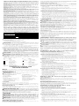
FREE WARNING LABEL REPLACEMENT: If your warning labels (Fig. 13) become illegible or
are missing, call 1-800-4-D
EWALT (1-800-433-9258) for a free replacement.
Défi nitions: lignes directrices en
matière de sécurité
Les définitions ci-dessous décrivent le niveau de danger pour chaque
mot-indicateur employé. Lire le mode d’emploi et porter une attention particulière
à ces symboles.
DANGER : indique une situation dangereuse imminente qui, si elle n’est pas
évitée, entraînera la mort ou des blessures graves.
AVERTISSEMENT: indique une situation potentiellement dangereuse qui,
si elle n’est pas évitée, pourrait entraîner la mort ou des blessures graves.
ATTENTION : indique une situation potentiellement dangereuse qui, si elle
n’est pas évitée, pourrait entraîner des blessures légères ou modérées.
AVIS : indique une pratique ne posant aucun risque de dommages corporels
mais qui par contre, si rien n’est fait pour l’éviter, pourrait poser des risques de
dommages matériels.
POUR TOUTE QUESTION OU REMARQUE AU SUJET DE CET OUTIL OU DE TOUT
AUTRE OUTIL D
EWALT, COMPOSEZ LE NUMÉRO SANS FRAIS : 1-800-4-DEWALT
(1-800-433-9258).
AVERTISSEMENT : afin de réduire le risque de blessures, lire le mode d’emploi de l’outil.
Avertissements de sécurité généraux pour les outils
électriques
AVERTISSEMENT ! Lire tous les avertissements de sécurité et toutes les
directives. Le non-respect des avertissements et des directives pourrait se solder par
un choc électrique, un incendie et/ou une blessure grave.
CONSERVER TOUS LES AVERTISSEMENTS ET TOUTES LES
DIRECTIVES POUR UN USAGE ULTÉRIEUR
Le terme « outil électrique » cité dans les avertissements se rapporte à votre outil électrique à
alimentation sur secteur (avec fil) ou par piles (sans fil).
1) SÉCURITÉ DU LIEU DE TRAVAIL
a) Tenir l’aire de travail propre et bien éclairée. Les lieux encombrés ou sombres sont
propices aux accidents.
b) Ne pas faire fonctionner d’outils électriques dans un milieu déflagrant, tel qu’en
présence de liquides, de gaz ou de poussières inflammables. Les outils électriques
produisent des étincelles qui pourraient enflammer la poussière ou les vapeurs.
c) Éloigner les enfants et les personnes à proximité pendant l’utilisation d’un outil
électrique. Une distraction pourrait en faire perdre la maîtrise à l’utilisateur.
2) SÉCURITÉ EN MATIÈRE D’ÉLECTRICITÉ
a) Les fiches des outils électriques doivent correspondre à la prise. Ne jamais
modifier la fiche d’aucune façon. Ne jamais utiliser de fiche d’adaptation avec un
outil électrique mis à la terre. Le risque de choc électrique sera réduit par l’utilisation
de fiches non modifiées correspondant à la prise.
b) Éviter tout contact physique avec des surfaces mises à la terre comme des
tuyaux, des radiateurs, des cuisinières et des réfrigérateurs. Le risque de choc
électrique est plus élevé si votre corps est mis à la terre.
c) Ne pas exposer les outils électriques à la pluie ou à l’humidité. La pénétration de
l’eau dans un outil électrique augmente le risque de choc électrique.
d) Ne pas utiliser le cordon de façon abusive. Ne jamais utiliser le cordon pour
transporter, tirer ou débrancher un outil électrique. Tenir le cordon éloigné de
la chaleur, de l’huile, des bords tranchants et des pièces mobiles. Les cordons
endommagés ou enchevêtrés augmentent les risques de choc électrique.
e) Pour l’utilisation d’un outil électrique à l’extérieur, se servir d’une rallonge
convenant à cette application. L’utilisation d’une rallonge conçue pour l’extérieur
réduira les risques de choc électrique.
f) S’il est impossible d’éviter l’utilisation d’un outil électrique dans un endroit
humide, brancher l’outil dans une prise ou sur un circuit d’alimentation dotés
d’un disjoncteur de fuite à la terre (GFCI). L’utilisation de ce type de disjoncteur réduit
les risques de choc électrique.
3) SÉCURITÉ PERSONNELLE
a) Être vigilant, surveiller le travail effectué et faire preuve de jugement lorsqu’un
outil électrique est utilisé. Ne pas utiliser d’outil électrique en cas de fatigue
ou sous l’influence de drogues, d’alcool ou de médicaments. Un simple moment
d’inattention en utilisant un outil électrique peut entraîner des blessures corporelles
graves.
b) Utiliser des équipements de protection individuelle. Toujours porter une
protection oculaire. L’utilisation d’équipements de protection comme un masque
antipoussière, des chaussures antidérapantes, un casque de sécurité ou des protecteurs
auditifs lorsque la situation le requiert réduira les risques de blessures corporelles.
c) Empêcher les démarrages intempestifs. S’assurer que l’interrupteur se trouve
à la position d’arrêt avant de relier l’outil à une source d’alimentation et/ou
d’insérer un bloc-piles, de ramasser ou de transporter l’outil. Transporter un outil
électrique alors que le doigt repose sur l’interrupteur ou brancher un outil électrique dont
l’interrupteur est à la position de marche risque de provoquer un accident.
d) Retirer toute clé de réglage ou clé avant de démarrer l’outil. Une clé ou une clé de
réglage attachée à une partie pivotante de l’outil électrique peut provoquer des blessures
corporelles.
e) Ne pas trop tendre les bras. Conserver son équilibre en tout temps. Cela permet
de mieux maîtriser l’outil électrique dans les situations imprévues.
f) S’habiller de manière appropriée. Ne pas porter de vêtements amples ni de
bijoux. Garder les cheveux, les vêtements et les gants à l’écart des pièces
mobiles. Les vêtements amples, les bijoux ou les cheveux longs risquent de rester
coincés dans les pièces mobiles.
g) Si des composants sont fournis pour le raccordement de dispositifs de
dépoussiérage et de ramassage, s’assurer que ceux-ci sont bien raccordés et
utilisés. L’utilisation d’un dispositif de dépoussiérage peut réduire les dangers engendrés
par les poussières.
4) UTILISATION ET ENTRETIEN D’UN OUTIL ÉLECTRIQUE
a) Ne pas forcer un outil électrique. Utiliser l’outil électrique approprié à l’application.
L’outil électrique approprié effectuera un meilleur travail, de façon plus sûre et à la vitesse
pour laquelle il a été conçu.
b) Ne pas utiliser un outil électrique dont l’interrupteur est défectueux. Tout outil
électrique dont l’interrupteur est défectueux est dangereux et doit être réparé.
c) Débrancher la fiche de la source d’alimentation et/ou du bloc-piles de l’outil
électrique avant de faire tout réglage ou changement d’accessoire ou avant de
ranger l’outil. Ces mesures préventives réduisent les risques de démarrage accidentel
de l’outil électrique.
d) Ranger les outils électriques hors de la portée des enfants et ne permettre à
aucune personne n’étant pas familière avec un outil électrique ou son mode
d’emploi d’utiliser cet outil. Les outils électriques deviennent dangereux entre les
mains d’utilisateurs inexpérimentés.
e) Entretien des outils électriques. Vérifier si les pièces mobiles sont mal alignées
ou coincées, si des pièces sont brisées ou présentent toute autre condition
susceptible de nuire au bon fonctionnement de l’outil électrique. En cas de
dommage, faire réparer l’outil électrique avant toute nouvelle utilisation.
Beaucoup d’accidents sont causés par des outils électriques mal entretenus.
f) S’assurer que les outils de coupe sont aiguisés et propres. Les outils de coupe bien
entretenus et affûtés sont moins susceptibles de se coincer et sont plus faciles à maîtriser.
g) Utiliser l’outil électrique, les accessoires, les forets, etc. conformément aux
présentes directives en tenant compte des conditions de travail et du travail
à effectuer. L’utilisation d’un outil électrique pour toute opération autre que celle pour
laquelle il a été conçu est dangereuse.
5) RÉPARATION
a) Faire réparer l’outil électrique par un réparateur professionnel en n’utilisant
que des pièces de rechange identiques. Cela permettra de maintenir une utilisation
sécuritaire de l’outil électrique.
Règles de sécurité spécifi que concernant les toupies
• Tenir l’outil électrique par ses parties isolées, car l’organe de coupe pourrait
entrer en contact avec son cordon. Couper un fil sous tension pourra mettre les parties
métalliques exposées de l’outil électrique sous tension et électrocuter l’utilisateur.

FIXED BASE - BASE FIXE - BASE FIJA
C
V
W
FIG. 1A
D
Y
FIG. 4
FIG. 5
1
4
3
2
FIG. 11
G
FIG. 12
D
A
Z
X
FIG. 2
H
B
C
FIG. 3
I
J
FIG. 6
BB
CC
R
FIG. 8
FF
EE
DD
GG
Q
F
T
P
HH
II
FIG. 9
KK
JJ
LL
FIG. 10
D
B
A
E
F
M
FIG. 1
CENTERING TOOL
OUTIL DE CENTRAGE
HERRAMIENTA DE CENTRADO
(DNP617)
SOLD SEPARATELY
VENDU SÉPARÉMENT
VENDIDA EN FORMA SEPARADA
D-HANDLE BASE - BASE DE LA POIGNÉE FERMÉE
BASE CON MANGO EN D
N
O
L
M
F
B
C
H
I
J
G
K
MOTOR - BLOC MOTEUR - UNIDAD DEL MOTOR
PLUNGE BASE - BASE PLONGEANTE - BASE PARA PENETRACIÓN
M
P
Q
R
T
S
F
Z
AA
L
N
O
K
FIG. 7
X
FIG. 13
SPEED SELECTION CHART
DIAL SETTING APPROX. RPM
1 8,000
2 12,000
3 14,000
4 18,000
5 21,000
6 24,000
The speeds in this chart are approximate and are
for reference only. Your router may not produce
the exact speed listed for the dial setting.
WARNING: Always follow the bit manufacturer’s
speed recommendations as some bit designs
require specific speeds for safety or performance.
If you are unsure of the proper speed or are
experiencing any type of problem, contact the bit
manufacturer.
SÉLECTION DE VITESSE
RÉGLAGE CADRAN R/MIN APPROX. R/MIN
1 8 000
2 12 000
3 14 000
4 18 000
5 21 000
6 24 000
Les vitesses de ce tableau sont approximatives et
ne sont données qu’à titre de référence. Il se pourra
que votre toupie ne produise pas exactement la
vitesse donnée pour un réglage spécifique du
cadran.
AVERTISSEMENT : suivre systématiquement
les recommandations du fabricant de forets quant
à la vitesse, car certains forets ont été conçus
pour des vitesses spécifiques pour des raisons de
sécurité ou de performances.
Si vous n’êtes pas sûr de la vitesse correcte
ou rencontrez un problème quelconque, veuillez
contacter le fabricant du foret.
SELECCIÓN DE VELOCIDAD
POSICIÓN DEL SELECTOR RPM APROXIMADAS
1 8 000
2 12 000
3 14 000
4 18 000
5 21 000
6 24 000
Las velocidades que aparecen en esta tabla son
aproximadas y se ofrecen solamente a título de
referencia. Su rebajadora quizás no produzca la
velocidad exacta indicada para la posición del
selector.
ADVERTENCIA: Siga siempre las
recomendaciones de velocidad del fabricante de
la broca puesto que algunos diseños de broca
requieren velocidades específicas por razones de
seguridad o rendimiento.
Si no está seguro de la velocidad adecuada o
tiene cualquier tipo de problema, contacte con el
fabricante de la broca.
U
E
D
Page is loading ...
Page is loading ...
Page is loading ...
Page is loading ...
-
 1
1
-
 2
2
-
 3
3
-
 4
4
-
 5
5
-
 6
6
-
 7
7


Ask a question and I''ll find the answer in the document
Finding information in a document is now easier with AI
in other languages
- français: DeWalt DW618D Manuel utilisateur
- español: DeWalt DW618D Manual de usuario