Page is loading ...

Owner’s Manual
1111 W. 35th Street, Chicago, IL 60609 USA
www.tripplite.com/support
Important Safety Instructions 2
Mounting 3
Quick Installation 5
Basic Operation 7
Battery Cartridge Replacement 11
Español 13
Copyright © 2010 Tripp Lite. All rights reserved. SmartPro
®
is a registered trademark of Tripp Lite.
Dual Voltage SmartPro
®
Rackmount
Intelligent, Line-Interactive UPS Systems
AC Input: 120/230V AC (50/60Hz) Auto Detect
AC Output: 120V AC (50/60Hz)
Optional Connections 6
Warranty Registration 12
Ðóññêèé 37
Not suitable for mobile applications.
Storage and Service 11
Français 25
WARRANTY
REGISTRATION
Register online today for a chance
to win a FREE Tripp Lite product!
www.tripplite.com/warranty
200912137 93-2968.indb 1 2/19/2010 10:38:09 AM

2
Important Safety Instructions
SAVE THESE INSTRUCTIONS
This manual contains important instructions that should be followed during the installation, operation
and storage of this product. Failure to heed these warnings will void your warranty.
UPS Location Warnings
• UsecautionwhenliftingtheUPS.BecauseoftheconsiderableweightofallrackmountUPS
systems, at least two people should assist in lifting and installing them.
• InstalltheUPSindoors,awayfromexcessmoistureorheat,dustordirectsunlight.
• Forbestperformance,theambienttemperatureneartheUPSshouldbebetween0°Cand40°C
(between32°Fand104°F).
• LeaveadequatespacearoundallsidesoftheUPSforproperventilation.Donotobstructitsventsor
fan openings.
• WhenmountingtheUPSsysteminatowerorientation,makesuretheLED/controlpanelisatthe
topoftheUPS,notatthebottom.
• Donotmountunitwithitsfrontorrearpanelfacingdown(atanyangle).Mountinginthismanner
will seriously inhibit the unit’s internal cooling, eventually causing product damage not covered
under warranty.
UPS Connection Warnings
• TheUPScontainsitsownenergysource(battery).Theoutputterminalsmaybeliveevenwhenthe
UPSisnotconnectedtoanACsupply.
• ConnecttheUPStoaproperlygroundedACpoweroutlet.DonotmodifytheUPS’spluginaway
thatwouldeliminatetheUPS’sconnectiontoground.DonotuseadaptersthateliminatetheUPS’s
connection to ground.
• DonotplugtheUPSintoitself;thiswilldamagetheUPSandvoidyourwarranty.
• IfyouareconnectingtheUPStoamotor-poweredACgenerator,thegeneratormustprovide
filtered,frequency-regulatedcomputer-gradeoutput.ConnectingtheUPStoageneratorwillvoidits
UltimateLifetimeInsurance.
Equipment Connection Warnings
• Useofthisequipmentinlifesupportapplicationswherefailureofthisequipmentcanreasonably
beexpectedtocausethefailureofthelifesupportequipmentortosignificantlyaffectitssafety
oreffectivenessisnotrecommended.Donotusethisequipmentinthepresenceofaflammable
anestheticmixturewithair,oxygenornitrousoxide.
• DonotconnectsurgesuppressorsorextensioncordstotheoutputoftheUPS.Thismightoverload
theUPSandmayaffectthesurgesuppressorandUPSwarranties.
Battery Warnings
• Batteriescanpresentariskofelectricalshockandburnfromhighshort-circuitcurrent.Observe
properprecautions.Donotdisposeofthebatteriesinafire.DonotopentheUPSorbatteries.Do
notshortorbridgethebatteryterminalswithanyobject.Usetoolswithinsulatedhandles.There
arenouser-serviceablepartsinsidetheUPS.Batteryreplacementshouldbeperformedonlyby
authorizedservicepersonnelusingthesamenumberandtypeofbatteries(SealedLead-Acid).The
batteriesarerecyclable.Refertoyourlocalcodesfordisposalrequirementsorvisitwww.tripplite.
com/UPSbatteryrecyclingforrecyclinginformation.TrippLiteoffersacompletelineofUPS
SystemReplacementBatteryCartridges(R.B.C.).VisitTrippLiteontheWebatwww.tripplite.com/
support/battery/index.cfmtolocatethespecificreplacementbatteryforyourUPS.
• Duringhot-swapbatteryreplacement,theUPSwillnotprovidebackuppowerintheeventofa
blackoutorotherpowerinterruptions.
• DonotoperatetheUPSwithoutbatteries.
• Whenaddingexternalbatterypackstoselectmodelswithexternalbatterypackconnectors,connect
onlyTrippLite-recommendedbatterypacksofthecorrectvoltageandtype.Donotconnector
disconnectbatterypackswhentheUPSisoperatingonbatterypower.
200912137 93-2968.indb 2 2/19/2010 10:38:09 AM

3
Mounting (Rack)
Mountyourequipmentineithera2-postor4-postrackorrackenclosure.Theusermustdeterminethe
fitnessofhardwareandproceduresbeforemounting.Ifhardwareandproceduresarenotsuitableforyour
application,contactthemanufacturerofyourrackorrackenclosure.Theproceduresdescribedinthis
manualareforcommonrackandrackenclosuretypesandmaynotbeappropriateforallapplications.
Note: The illustrations may differ from your model.
2-Post Mounting
TrippLite’s2-PostRackmountInstallationKit(Model:2POSTRMKITHD)isincludedwithyourUPS
systemforrackmountingpurposesandconvenience.
Important: Illustrations show the most typical installation configuration; your model may vary. Use
only the pre-drilled screw holes to attach mounting brackets to the sides of the unit. When installing
battery packs into the rack, ensure that the weight of the unit is evenly distributed.
4-Post Mounting
TrippLite’s4-PostRackmountInstallationKit(Model:4POSTRAILKIT)isalsoincludedwithyourUPS
systemforrackmountingpurposesandconvenience.
The included plastic pegs
A
will temporarily
supporttheemptyrackmountshelves
B
while
you install the permanent mounting hardware.
Insertapegnearthecenterofthefrontandrear
bracket of each shelf as shown. (Each front
brackethas6holesandeachrearbrackethas3
holes.)Thepegswillsnapintoplace.
Afterinstallingthepegs,expandeachshelfto
match the depth of your rack rails.The pegs
will fit through the square holes in the rack
railsto supportthe shelves.Referto therack
unit labels to confirm that the shelves are level
in all directions. Note: The support ledge of
each shelf must face inward.
Secure the shelves
B
to the mounting rails
permanently using the included screws and cup
washers
C
as shown.
• For3Uequipmentmounting,place6screws
total at the front and 4 screws total at the
back.
Warning: Do not attempt to install your
equipment until you have inserted and
tightened the required screws. The plastic
pegs will not support the weight of your
equipment.
1
2
3U
3U
X 8
X 4
X 4
1
2 3
A
A
B
C
C
B
1
2
200912137 93-2968.indb 3 2/19/2010 10:38:12 AM

4
Mounting (Rack) continued
3
4
Mounting (Tower)
Mountallmodulesinanupright,towerpositionusingincludedbasestands(Model:2-9USTAND).The
user must determine the fitness of hardware and procedures before mounting.
Attachyourequipment’smountingbracketsto
the forward mounting holes of the cabinet using
the hardware included with your equipment.
The mounting bracket “ears” should face
forward. (Some equipment may have pre-
installedorintegralmountingbrackets.)
Withtheaidofanassistant(ifnecessary),lift
your equipment and slide it into the shelves.
Attachtheequipmentmountingbracketstothe
forward mounting rails with user-supplied
screws and washers
D
. (For 3U installation,
user-supplied nuts are also required.) Tighten
all screws securely.
TheUPSsystemisshippedwithtwosetsofplasticfeet
A
and
extensions
B
thatcanbeusedtotowermounttheUPS’spower
module(3U), abattery module anda second batterymodule
(upto9Utotal).
Adjustthefeettoawidthof5.25inches(13.3cm)fortheUPS
power module. Align the feet in your installation area,
approximately 10 inches (26 cm) apart. Have one or more
assistants help you place the units on their sides in the feet. The
controlpaneloftheUPSshouldbetheUPS’suppercornerand
face outward.
D
3
4
A
B
Note: Graphic represents a power module,
first and second battery module (9U)
configuration.
200912137 93-2968.indb 4 2/19/2010 10:38:14 AM

5
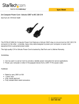
Quick Installation
Insert one of the supplied input cords*
or a user-supplied input cord with
country-specific plug into the UPS
system’s IEC-320-C20 AC inlet.
*Included input cordsets include: NEMA 5-20P, Schuko
CEE7/EUI-16P, British BS 1363A and Italian CEI 23-16 to
IEC-320-C19.
Plug the UPS into an outlet on a
dedicated circuit.
NOTE! After you plug the UPS into a live AC outlet,
the UPS (in “Standby” mode) will automatically
charge its batteries, but will not supply power to its
outlets until it is turned ON.
Plug your equipment into the UPS.*
* Your UPS is designed to support only electronic equipment. You will
overload the UPS if the total VA ratings for all the equipment you
connect exceeds the UPS’s Output Capacity. To find your equipment’s
VA ratings, look on their nameplates. If the equipment is listed in
amps, multiply the number of amps by 120 to determine VA. (Example:
1 amp × 120 = 120 VA). If you are unsure if you have overloaded the
UPS’s outlets, see “OUTPUT LOAD LEVEL” LED description.
Turn the UPS ON.
Pressandholdthe“ON/OFF/STANDBY”button
A
for one
second. The alarm will beep once briefly after one second
has passed. Release the button.
Note: UPS system will function properly upon initial startup, however,
maximum runtime for the unit’s battery will only be accessible after it
has been charged for 24 hours.
1
2
3
4
1
3
SMARTPRO
®
U P S
4
A
200912137 93-2968.indb 5 2/19/2010 10:38:16 AM

6
Optional Connections
These connections are optional. Your UPS will function
properly without these connections.
USB and RS-232 Serial
Communications
UsetheincludedUSBcable(see
1a
)orDB9serialcable
(see
1b
) to connect the communication port on your
computertothecommunicationportofyourUPS.Install
on your computer the Tripp Lite PowerAlert software
appropriate to your computer’s operating system.
EPO Port Connection
This optional feature is only for those applications which
require connection to a facility’s Emergency Power Off
(EPO)circuit.WhentheUPSisconnectedtothiscircuit,
itenablesemergencyshutdownoftheUPS’sinverter.
Usingthecable provided,connectthe EPOport ofyour
UPS (see
2a
) to a user-supplied normally closed or
normally open switch according to the circuit diagram (see
2b
).TheEPOportisnotaphonelinesurgesuppressor;do
not connect a phone line to this port.
External Battery Connection
Your UPS comes with a robust internal battery
system; external batteries are needed only to extend
runtime.Addingexternalbatterieswillincreaserecharge
time as well as runtime.
The illustration (see
3
)showsthelocationofyourUPS’s
ExternalBatteryConnector
A
, where you will insert the
batterypackcable.Completeinstallationinstructionsfor
your battery pack appear in the battery pack owner’s
manual.Makesurethatcablesarefullyinsertedintotheir
connectors. Small sparks may result during battery
connection;thisisnormal.
DonotconnectordisconnectbatterypackswhentheUPS
is running on battery power.
1
2
3
4-5
1b
1a
2a
2b
3
A
200912137 93-2968.indb 6 2/19/2010 10:38:20 AM

7
“ON/OFF/STANDBY” Button
• To turn the UPS ON:withtheUPSpluggedintoaliveACwalloutlet*,pressand
holdthe“ON/OFF/STANDBY”buttonforonesecond.**Release thebutton.If
utilitypowerisabsent,youcan“cold-start”theUPS(i.e.:turnitONandsupply
powerforalimitedtimefromitsbatteries***)bypressingandholdingthe“ON/
OFF/STANDBY”buttonforonesecond.**
• To turn the UPS OFF:withtheUPSONandreceivingutilitypower,pressand
holdthe“ON/OFF/STANDBY”buttonforonesecond.**ThenunplugtheUPS
fromthewalloutlet.TheUPSwillbecompletelyOFF.
* After you plug the UPS into a live AC outlet, the UPS (in ”Standby” mode) will automatically charge
its batteries, but will not supply power to its outlets until it is turned ON. ** The alarm will beep
once briefly after the indicated interval has passed. *** If fully charged.
“MUTE/TEST”Button
To Silence (or “Mute”) UPS Alarms:brieflypressandreleasetheMUTE/TEST
button.*
To Run a Self-Test:withyourUPSpluggedinandturnedON,pressandholdthe
MUTE/TEST button. Continue holding the button until the alarm beeps
severaltimesandtheUPSperformsaselftest.See“ResultsofaSelf-Test”below.
Note:youcanleaveconnectedequipmentonduringaself-test.YourUPS,however,
willnotperformaself-testiftheUPSisnotturnedon(see“ON/OFF/STANDBY”
Buttondescription).
CAUTION! Do not unplug your UPS to test its batteries. This will remove safe
electrical grounding and may introduce a damaging surge into your network
connections.
Results of a Self-Test: The test will last approximately 10 seconds as the UPS
switches to battery to test its load capacity and battery charge.
• Ifthe“OUTPUTLOADLEVEL”LEDremainslitredandthealarmcontinuesto
sound after the test, the UPS’s outlets are overloaded. To clear the overload,
unplug some of your equipment and run the self-test repeatedly until the
“OUTPUTLOADLEVEL”LEDisnolongerlitredandthealarmisnolonger
sounding.
CAUTION! Any overload that is not corrected by the user immediately
following a self-test may cause the UPS to shut down and cease supplying
output power in the event of a blackout or brownout.
• Ifthe“BATTERYWARNING”LEDremainslitandthealarmcontinuestosound
afterthetest,theUPSbatteriesneedtoberechargedorreplaced.AllowtheUPS
torechargecontinuouslyfor12hoursandrepeattheself-test.IftheLEDremains
lit,contactTrippLiteforservice.IfyourUPSrequiresbatteryreplacement,visit
www.tripplite.comtolocatethespecificTrippLitereplacementbatteryforyour
UPS.
* Overload alarms and battery alarms only.
Basic Operation
Buttons (Front Panel)
200912137 93-2968.indb 7 2/19/2010 10:38:21 AM

8
Basic Operation continued
Indicator Lights (Front Panel)
AllIndicatorLightdescriptionsapplywhentheUPSispluggedintoawalloutlet
andturnedON.
“POWER” LED: thisgreenLEDlights continuously when the UPS is ON and
supplying connected equipment withAC power from a utility source. The LED
flashesandanalarmsounds(4shortbeepsfollowedbyapause)toindicatetheUPS
isoperatingfromitsinternalbatteriesduringablackoutorseverebrownout.Ifthe
blackoutorseverebrownoutisprolonged,youshouldsavefilesandshutdownyour
equipmentsinceinternalbatterypowerwilleventuallybedepleted.See“BATTERY
CHARGE”LEDdescriptionbelow.
“VOLTAGE CORRECTION” LED:thisgreenLEDlightscontinuouslywhenever
the UPS is automatically correcting high or low AC voltage on the utility line
withoutthe assistanceof batterypower.TheUPSwill alsoemit aslight clicking
noise.Thesearenormal,automaticoperationsoftheUPS;noactionisrequiredon
your part.
“OUTPUT LOAD LEVEL” LED: thismulticoloredLEDindicatestheapproximate
electricalloadofequipmentconnectedtotheUPS’sACoutlets.Itwillturnfrom
green (light load) to yellow (medium load) to red (overload). If the LED is red
(either illuminated continuously or flashing), clear the overload immediately by
unpluggingsomeofyourequipmentfromtheoutletsuntiltheLEDchangesfrom
redtoyellow(orgreen).CAUTION! Any overload that is not corrected by the
user immediately may cause the UPS to shut down and cease supplying output
power in the event of a blackout or brownout.
“BATTERY CHARGE” LED: whentheUPSisoperatingfromutilitypower,this
LED indicates the approximate charge state of the UPS’s internal batteries: red
indicates the batteries are beginningto charge; yellow indicates the batteries are
roughly midway through charging; and green indicates the batteries are fully
charged.WhentheUPSisoperatingfrombatterypowerduringablackoutorsevere
brownout, this LED indicates the approximate amount of energy (ultimately
affectingruntime)whichtheUPS’sbatterieswillprovide:redindicatesalowlevel
ofenergy;yellowindicatesamediumlevelofenergy;andgreenindicatesahigh
levelofenergy.SincetheruntimeperformanceofallUPSbatterieswillgradually
depleteovertime,itisrecommendedthatyouperiodicallyperformaself-test(see
MUTE/TEST Button description) to determine the energy level of your UPS
batteries BEFORE a blackout or severe brownout occurs. During a prolonged
blackoutorseverebrownout,youshouldsavefilesandshutdownyourequipment
sincebattery powerwilleventuallybe depleted.WhentheLED turnsred andan
alarmsoundscontinuously,itindicatestheUPS’sbatteriesarenearlyoutofpower
andUPSshutdownisimminent.
“BATTERY WARNING” LED: this LED lights red and an alarm sounds
intermittentlyafteryouinitiateaselftest(See“MUTE/TEST”Buttondescription)
toindicatetheUPSbatteriesneedtoberechargedorreplaced.AllowtheUPSto
rechargecontinuouslyfor12hours,andrepeattheself-test.IftheLEDcontinuesto
light,contactTrippLiteforservice.IfyourUPSrequiresbatteryreplacement,visit
www.tripplite.com to locate the specific Tripp Lite replacement battery for your
UPS.
200912137 93-2968.indb 8 2/19/2010 10:38:21 AM

9
Basic Operation continued
Other UPS Features (Rear Panel)
AC Outlets: thismodelincludesNEMA5-15RandNEMA5-15/20Routlets.These
outlets provide your connected equipment with AC line power during normal
operation and battery power during blackouts and brownouts. The UPS protects
equipmentconnectedtotheseoutletsagainstdamagingsurgesandlinenoise.Ifyou
haveaserialorUSBconnectiontoyourUPS,youcanremotelyrebootconnected
equipment by turning select outlets OFF and ON using Tripp Lite’s PowerAlert
software.Theoutletsaredividedintooneormoreloadbanks(labelled“LOAD1,”
etc.)whichmayberemotelyswitchedOFFandONwithoutinterruptingpowerto
equipmentconnectedtotheotheroutlets.Outletslabelled“UNSWITCHED”may
not be remotely switched off.
Detachable AC Input Cords (Included): four country-specific detachable AC
inputcords(NEMA5-20P,SchukoCEE7/EUI-16P,BritishBS1363AandItalian
CEI23-16)areincludedtoallowUPSusageindifferentcountries.
Communication Ports (USB or RS-232): these ports connect your UPS to any
workstationorserver.UsewithTrippLite’sPowerAlertsoftwareandincludedcables
toenableyourcomputertoautomaticallysaveopenfilesandshutdownequipment
duringablackout.AlsousePowerAlertsoftwaretomonitorawidevarietyofACline
powerandUPSoperatingconditions.ConsultyourPowerAlertsoftwaremanualor
contactTrippLiteCustomerSupportformoreinformation.See“USBandRS-232
Serial Communications” in the “Optional Installation” section for installation
instructions.
EPO (Emergency Power Off) Port: yourUPSfeaturesaEPOportthatmaybeused
to connect the UPS to a contact closure switch to enable emergency inverter
shutdown.SeeOptionalInstallation.
Accessory Slot: remove the small cover panel from this slot to install optional
accessories to remotely monitor and control your UPS. Refer to your accessory’s
manualforinstallationinstructions.Visitwww.tripplite.comformore information,
includingalistofavailableSNMP,networkmanagementandconnectivityproducts.
15A 120V
NEMA 5-15R
20A 120V
NEMA 5-15/20R
NEMA 5-20P Schuko CEE7/
EUI-16P
BS 1363A CEI 23-16
200912137 93-2968.indb 9 2/19/2010 10:38:23 AM

10
Basic Operation continued
Power Sensitivity Adjustment: thisdialisnormallysetfullycounter-clockwise,
whichenablestheUPStoprovidemaximumprotectionagainstwaveformdistortions
in its AC input. When such distortion occurs, the UPS will normally switch to
providing sine wave power from its battery reserves for as long as the
distortionispresent.InareaswithpoorutilitypowerorwheretheUPS’sinputpower
comesfromabackupgenerator,chronicwaveformdistortioncouldcausetheUPS
toswitchtobatterytoofrequently,drainingitsbatteryreserves.Youmaybeableto
reducehowoftenyourUPSswitchestobatteryduetomoderatewaveformdistortion
byexperimentingwithdifferentsettingsforthisdial.Asthedialisturnedclockwise,
the UPS becomes more tolerant of variations in its input power’sACwaveform.
NOTE:Thefurtherthedialisadjustedclockwise,thegreaterthedegreeofwaveform
distortiontheUPSwillallowtopasstoconnectedequipment.Whenexperimenting
withdifferentsettingsforthisdial,operateconnectedequipmentinasafetestmode
sothattheeffectontheequipmentofanywaveformdistortionsintheUPS’soutput
can be evaluated without disrupting critical operations.
External Battery Connector (optional): usetoconnectTrippLiteexternalbattery
packsforadditionalruntime.Refertoinstructionsavailablewiththebatterypackfor
complete connection information and safety warnings.
Input Breaker: protectsyourelectricalcircuitfromovercurrentdrawfromtheUPS
load.Ifthisbreakertrips,reducetheload,thenresetbypressingthebreakerin.
Output Breaker: yourUPSfeaturesanoutputbreakerthatprotectsyourUPSfrom
outputoverload.Ifthisbreakertrips,removesomeoftheloadonthecircuit,then
resetbypressingthebreakerin.
Ground Screw: usethistoconnectanyequipmentthatrequiresachassisground.
200912137 93-2968.indb 10 2/19/2010 10:38:23 AM

11
Battery Cartridge Replacement
Undernormalconditions,theoriginalbatterycartridgesinyourUPSwilllastmanyyears.SeeSafety
section before replacing batterycartridges.Thebatterycartridgesaredesignedforhot-swapreplacement (i.e.
leavingtheUPSinONmode),butsomequalifiedservicepersonnelmaywishtoputtheUPSintheOFF
modeanddisconnectequipmentbeforeproceeding.
Procedure
1
Remove the screws
A
which secure the front bezel.
2
Separate the front bezel
B
from the front panel. Note:
The front bezel will NOT completely detach from the
front panel, as it is connected to the unit's LED wiring
connection strip. DO NOT SEVER OR ALTER THIS
STRIP IN ANY WAY.
3
Remove the screws
C
that secure the battery retention
bracket
D
. Slide the bracket to the left, then out
towards you.
4
Disconnect the front battery cartridge's connectors
E
and
remove/recycle the front battery cartridge. Reach into the
unit to pull the rear battery cartridge to the front,
disconnect it’s connectors and remove/recycle the rear
battery cartridge.
5
Replace the rear battery cartridge and connect its
connectors
E
black-to-black and red-to-red, then push it
all the way back into the unit. Replace the front battery
cartridge and connect its connectors black-to-black and
red-to-red.
6
Replace the battery retention bracket
D
by sliding it in to
the left, then back behind the brace and re-attach the
screws
C
.
7
Replace the front bezel
B
.
8
Replace the screws
A
to secure the front bezel in place.
Storage and Service
Storage
BeforestoringyourUPS,turnitcompletelyOFF:withtheUPSONandreceivingutilitypower,pressand
holdthe“ON/OFF/STANDBY”buttonforonesecond(analarmwillbeeponcebrieflyaftertheinterval
haspassed);then,unplugtheUPSfromthewalloutlet.IfyoustoreyourUPSforanextendedperiodof
time,rechargetheUPSbatteriesonceeverythreemonths:plugtheUPSintoawalloutlet;allowitto
chargefor12hours;andthenunplugitandplaceitbackinstorage.Note:afteryouplugtheUPSin,it
willautomaticallybeginchargingitsbatteries;however,itwillnotsupplypowertoitsoutlets(seeQuick
Installationsection).IfyouleaveyourUPSbatteriesdischargedforanextendedperiodoftime,theywill
suffer a permanent loss of capacity.
1
8
2
7
3
4
6
5
A
B
C
E
D
200912137 93-2968.indb 11 2/19/2010 10:38:27 AM

12
FCC RADIO/TV INTERFERENCE NOTICE: (FOR CLASS A MODELS)
Note: This equipment has been tested and found to comply with the limits for a Class A digital device, pursuant to Part 15 of the FCC
Rules. These limits are designed to provide reasonable protection against harmful interference when operated in a commercial
environment. This equipment generates, uses and can radiate radio frequency energy, and if not installed and used in accordance with
the instruction manual, may cause interference to radio communications. Operation of this equipment is likely to cause harmful interference
in which case the user will be required to correct the interference at his own expense. The user must use shielded cables and connectors
with this product. Any changes or modifications to this product not expressly approved by the party responsible for compliance could void
the user’s authority to operate the equipment.
Regulatory Compliance Identification Numbers
For the purpose of regulatory compliance certifications and identification, your
Tripp Lite product has been assigned a unique series number. The series number
can be found on the product nameplate label, along with all required approval
markings and information. When requesting compliance information for this product,
always refer to the series number. The series number should not be confused with
the marking name or model number of the product.
Tripp Lite has a policy of continuous improvement. Product specifications
are subject to change without notice.
Storage and Service continued
Warranty Registration
Visit www.tripplite.com/warranty today to register the warranty for your newTrippLite product.You’ll be
automaticallyenteredintoadrawingforachancetowinaFREETrippLiteproduct!*
*Nopurchasenecessary.Voidwhereprohibited.Somerestrictionsapply.Seewebsitefordetails.
Note on Labeling
Two symbols are used on the label.
V~ : AC Voltage
V : DC Voltage
1111 W. 35th Street, Chicago, IL 60609 USA
www.tripplite.com/support
200912137 • 932968-EN
Service
Your Tripp Lite product is covered by the warranty described in this manual.A variety of Extended
Warranty and On-Site Service Programs are also available from Tripp Lite. For more information on
service,visitwww.tripplite.com/support.Beforereturningyourproductforservice,followthesesteps:
1.Reviewtheinstallationandoperationproceduresinthismanualtoinsurethattheserviceproblemdoes
not originate from a misreading of the instructions.
2.Iftheproblemcontinues,donotcontactorreturntheproducttothedealer.Instead,visitwww.tripplite.
com/support.
3.If the problem requiresservice,visit www.tripplite.com/supportand clicktheProduct Returns link.
FromhereyoucanrequestaReturnedMaterialAuthorization(RMA)number,whichisrequiredfor
service.Thissimpleon-lineformwillaskforyourunit’smodelandserialnumbers,alongwithother
generalpurchaserinformation.TheRMAnumber,alongwithshippinginstructionswillbeemailedto
you.Anydamages(direct,indirect,specialorconsequential)totheproductincurredduringshipmentto
TrippLiteoranauthorizedTrippLiteservicecenterisnotcoveredunderwarranty.Productsshippedto
TrippLiteoranauthorizedTrippLiteservicecentermusthavetransportationchargesprepaid.Markthe
RMAnumberontheoutsideofthepackage.Iftheproductiswithinitswarrantyperiod,encloseacopy
of your sales receipt. Return the product for service using an insured carrier to the address given to you
whenyourequesttheRMA.
200912137 93-2968.indb 12 2/19/2010 10:38:28 AM

Manual del propietario
1111 W. 35th Street, Chicago, IL 60609 USA
www.tripplite.com/support
Instrucciones importantes de seguridad 14
Montaje 15
Instalación rápida 17
Operación básica 19
Reemplazo del cartucho de baterías 23
Copyright © 2010 Tripp Lite. Reservados todos los derechos. SmartPro® es una marca comercial registrada de Tripp Lite.
SmartPro
®
de tensión
doble para montar en rack
Sistemas UPS interactivos e inteligentes
Entrada CA: 120/230V CA (50/60Hz) Detección automática
Salida CA: 120V AC (50/60Hz)
Conexiones opcionales 18
No es adecuado para aplicaciones móviles
Almacenamiento y mantenimiento 23
English 1
Ðóññêèé 37
Français 25
200912137 93-2968.indb 13 2/19/2010 10:38:29 AM
/