Intel Pentium M Box PC User manual
- Category
- Notebooks
- Type
- User manual
This manual is also suitable for
Intel Pentium M Box PC
The Intel Pentium M Box PC is a compact and versatile device that offers a range of capabilities for various applications.
Key Features:
- Powerful Performance: Powered by an Intel Pentium M processor, the Box PC delivers reliable performance for demanding tasks.
- Compact Design: Its small form factor makes it ideal for space-constrained environments, such as kiosks, information booths, and industrial settings.
- Fanless Operation: The fanless design ensures quiet operation and reduces the risk of dust accumulation, enhancing system reliability.
- Extensive Connectivity: Equipped with multiple serial ports, USB ports, Ethernet ports, and a Mini Card slot, the Box PC supports a wide range of peripherals and expansion options.

EX-98211
Fanless Intel Celeron/Pentium M
Box PC
Quick Installation Guide
Version 1.0

Chapter1 1 General Information
1.1 Introduction

1.2 Packing List
After opening the package, carefully inspect the contents. If any of items is missing or
appears damaged, please contact with your local dealer or distributor. The package
should contain the following items:
1 x EX-98211 Box PC
2 x EPE FOAM
1 x Accessory Box (CD/Quick Installation Guide/Screw/Cable)
1.3 System

1.4 Power Information
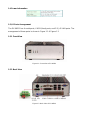
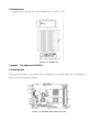
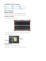
1.5 I/O Ports Arrangement
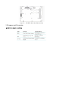
The EX-98211 has 4 serial ports, 6 USB (Host) ports, and 2 RJ-45 LAN ports. The
arrangement of these ports is shown in Figure 1.1 & Figure 1.2
1.5.1 Front View
Figure 1.1: Front View of EX-98211
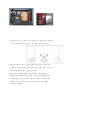
1.5.2 Back View
Figure 1.2: Back View of EX-98211

1.6 Dimensions
‧
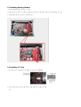
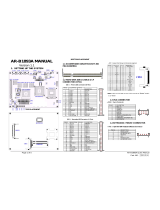
Chapter2 The Engine of EX-98211
2.1 Introduction

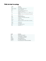
2.2 Jumpers and Connectors


JRS1 RS-232/422/485 Selection
JP1 LAN LED Connector

IDE1: Primary IDE Connector

CFD1: Compact Flash Disk (Share IDE1)
LPT1: Parallel Port Connector
SATA1~2: S-ATA1 Connector

LAN1/LAN2 Connector (USB Port 1, 2 ~ USB Port 3, 4)
USB1 Connector (USB Port 5, 6)
VGA1: CRT Connector
DVI1: DVI Connector

CN1: (COM1~4 +GPIO 2 In/2 Out Option RS422/485 output)
IR1: Infrared (IR) Connector
KBM1: PS/2 Keyboard & Mouse
AUDIO1: Audio Interface Port
PWRIN1: DC Adapter Power Input

RS-422/485, GPIO Function Jumper
Chapter 3 Maintenance
Hardware Installation
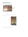
3.1 Remove Top Cover
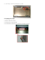
3.2 Installing CPU


3.3 Installing Memory Module
3.4 Installing CF Card

3.5 Remove Bottom Cover

3.6 Installing Hard Disk Drive

3.7 Installing Riser Card
1. Insert PCI card into the PCI slot.
2. Locate the screw on the slot bracket.
3. Use screw driver to remove the screw. Keep the screw safely for later use.

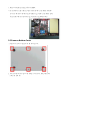
3.8 Installing Wall-mount Bracket
1. Upside down the Box PC. Please locate the 8 screw holes on the bottom
cover.
2. Match the screws on the wall-mount kit and screws onto the main unit.
-
 1
1
-
 2
2
-
 3
3
-
 4
4
-
 5
5
-
 6
6
-
 7
7
-
 8
8
-
 9
9
-
 10
10
-
 11
11
-
 12
12
-
 13
13
-
 14
14
-
 15
15
-
 16
16
-
 17
17
-
 18
18
-
 19
19


Intel Pentium M Box PC User manual
- Category
- Notebooks
- Type
- User manual
- This manual is also suitable for
Intel Pentium M Box PC
The Intel Pentium M Box PC is a compact and versatile device that offers a range of capabilities for various applications.
Key Features:
- Powerful Performance: Powered by an Intel Pentium M processor, the Box PC delivers reliable performance for demanding tasks.
- Compact Design: Its small form factor makes it ideal for space-constrained environments, such as kiosks, information booths, and industrial settings.
- Fanless Operation: The fanless design ensures quiet operation and reduces the risk of dust accumulation, enhancing system reliability.
- Extensive Connectivity: Equipped with multiple serial ports, USB ports, Ethernet ports, and a Mini Card slot, the Box PC supports a wide range of peripherals and expansion options.
Ask a question and I''ll find the answer in the document
Finding information in a document is now easier with AI
Related papers
Other documents
-
Albatron EM215 User manual
-
MasterCool 98211-A Operating instructions
-
Avaya BayRS, BCC, and Site Manager Software Version 14.20 Fixed Anomalies User manual
-
Ergotron SV32-92224 Datasheet
-
Ergotron SV32-91126 Datasheet
-
Ergotron SV42-42201 Datasheet
-
Sunrise Medical 7782 User manual
-
 Acrosser Technology AR-B1893A User manual
-
ADLINK Technology NuPRO-A301 User manual
-
Gigabyte GA-K8VM800M User manual
