Page is loading ...

Commercial
GEAppliances.com
DCB330
DCD330
134205200 175D1807P420 49-90156 11-02 JR
Safety Instructions . . . . . . . . . 2–5
Care and Cleaning
Care and Cleaning . . . . . . . . . . . .6
Installation Instructions
Countdown Display . . . . . . . . . . 17
Electrical Installation for
Electric Dryers . . . . . . . . . . . 13, 14
Electrical Requirements . . . . . . . . 8
Exhausting the Dryer . . . . . . . 9, 10
Gas Connection for Gas Dryers . . 15
Gas Supply Requirements . . . . . 10
Location of Your Dryer . . . . . . . . 11
Mobile Home Installation . . . . . 12
Preparing to Install Your Dryer . . 7
Reversing the Door Swing . . . . . 16
Customer Service
Customer Service . . . . . Back Cover
General Principles of
Good Practice . . . . . . . . . . . . . . . 19
Warranty . . . . . . . . . . . . . . . . . . . 18
Write the model and serial
numbers here:
Model # __________________
Serial # __________________
You can find them on the label
on the front of the left side of
the door opening.
Owner’s Manual and
Installation Instructions
Dryers
IMPORTANT SAFETY INFORMATION.
READ ALL INSTRUCTIONS BEFORE USING.
2
WARNING!
For your safety, the information in this manual must be followed to minimize the risk of fire
or explosion, electric shock, or to prevent property damage, personal injury, or death.
FOR GAS DRYERS: YOU MUST POST IN A PROMINENT LOCATION
1.
Instructions to follow if the user smells gas: Contact your local gas
supplier for information to be displayed.
2. Instructions concerning flammable materials as follows:
FOR YOUR SAFETY
Do not store or use gasoline or other flammable vapors and liquids
in the vicinity of this or any other appliance.
California Safe Drinking Water and Toxic Enforcement Act
This act requires the governor of California to publish a list of substances known to the state to cause cancer,
birth defects or other reproductive harm and requires businesses to warn customers of potential exposure
to such substances.
Gas appliances can cause minor exposure to four of these substances, namely benzene, carbon monoxide,
formaldehyde and soot, caused primarily by the incomplete combustion of natural gas or LP fuels.
Properly adjusted dryers will minimize incomplete combustion. Exposure to these substances can be
minimized further by properly venting the dryer to the outdoors.
Installation and service must be performed by a qualified installer, service agency or the gas
supplier.
Customer Service
Care and Cleaning
Safety Instructions
Installation Instructions
■ Properly ground dryer to conform with all
governing codes and ordinances. Follow details
in the Installation Instructions section.
■ Install or store where it will not be exposed to
temperatures below freezing or exposed to the
weather.
■ Connect to a properly rated, protected and sized
power supply circuit to avoid electrical overload.
■ Remove all sharp packing items and dispose of
all shipping materials properly.
■ In fulfilling the specific needs of different
commercial installations the purchaser of this
dryer may wish to locate the coin box and
controls in any of a number of locations.
The responsibility for the proper performance
of this work lies solely with the purchaser.
It should be done by properly trained and
qualified personnel, and in accordance with
local code requirements.
■ Any coin box or similar device added to
the dryer, either electrically or mechanically,
should be properly grounded.
■ Remove any accumulated time by manually
rotating timing cam in the coin box
counterclockwise until switch shuts off. Apply
a slight additional counterclockwise pressure to
further seat drive. Make certain not to turn cam
past switch shutoff position. Otherwise, one
increment of time will be gained. Switches are off
when the plastic switch actuating arm (inner)
is down and all 3 switch buttons are depressed.
Exhaust/Ducting:
This dryer MUST be exhausted to the outside.
Use only rigid metal or flexible metal 4″
diameter ductwork inside the dryer cabinet or
for exhausting to the outside. USE OF PLASTIC
OR OTHER COMBUSTIBLE DUCTWORK CAN
CAUSE A FIRE. PUNCTURED DUCTWORK CAN
CAUSE A FIRE IF IT COLLAPSES OR BECOMES
OTHERWISE RESTRICTED IN USE OR DURING
INSTALLATION.
Follow details in the Installation Instructions section.
2
1
PROPER INSTALLATION
This dryer must be properly installed and located in accordance with the Installation Instructions
before it is used.
3
Customer ServiceCare and Cleaning
Safety Instructions
Installation Instructions
GEAppliances.com

4
IMPORTANT SAFETY INSTRUCTIONS.
READ ALL INSTRUCTIONS BEFORE USING.
WARNING!
YOUR LAUNDRY AREA
■ Keep the area underneath and around your
appliances free of combustible materials, such
as lint, paper, rags, chemicals, gasoline and other
flammable vapors and liquids.
■ Keep the floor around your appliances clean and
dry to reduce the possibility of slipping.
■ Keep area around the exhaust opening and
surrounding areas free from the accumulation of
lint, dust and dirt.
■ Do not obstruct the flow of ventilating air. Do not
stack or place laundry or throw rugs against the
front or back of the dryer.
■ Close supervision is necessary if this appliance is
used by or near children. Do not allow children
to
play on, with, or inside this or any other
appliance.
■ Keep all laundry aids (such as detergents,
bleaches, etc.) out of the reach of children,
preferably in a locked cabinet. Observe all
warnings on container labels to avoid injury.
■ Never climb on or stand on the dryer top.
■ Do not install or store this appliance where it will
be exposed to the weather.
WHEN USING YOUR DRYER
■ Never reach into the dryer while the drum is
moving. Before loading, unloading or adding
clothes, wait until the drum has completely
stopped.
■ Clean the lint filter before each load to prevent lint
accumulation inside the dryer or in the room.
DO NOT OPERATE THE DRYER WITHOUT THE LINT
FILTER IN PLACE.
■ Do not wash or dry articles that have been
cleaned in, washed in, soaked in, or spotted
with combustible or explosive substances (such as
wax, oil, paint, gasoline, degreasers, dry-cleaning
solvents, kerosene, etc.) which may ignite or
explode. Do not add these substances to the
wash water. Do not use or place these substances
around your washer or dryer during operation.
■ Any article on which you have used a cleaning
solvent or that contains flammable materials
(such as cleaning cloths, mops, towels used in
beauty salons, restaurants, or barber shops, etc.)
must not be placed in or near the dryer until
solvents or flammable materials have been
removed. There are many highly flammable
items used in homes such as acetone, denatured
alcohol, gasoline, kerosene, some household
cleaners, some spot removers, turpentines,
waxes, wax removers and products containing
petroleum distillates.
■ The laundry process can reduce the flame
retardancy of fabrics. To avoid such a result,
carefully follow the garment manufacturer’s
care instructions.
■ Do not dry articles containing rubber, plastic,
or similar materials such as padded bras, tennis
shoes, galoshes, bath mats, rugs, bibs, baby pants,
plastic bags, pillows, etc. that may melt or burn.
Some rubber materials, when heated, can under
certain circumstances produce fire by
spontaneous combustion.
■ Do not store plastic, paper or clothing that
may
burn or melt on top of the dryer during
operation.
■ Garments labeled Dry Away from Heat or
Do Not Tumble Dry (such as life jackets containing
Kapok) must not be put in your dryer.
■ Do not dry fiberglass articles in your dryer.
Skin irritation could result from the remaining
particles that may be picked up by clothing
during subsequent dryer uses.
■ To minimize the possibility of electric shock,
unplug this appliance from the power supply
or disconnect the dryer at the distribution panel
by removing the fuse or switching off the circuit
breaker before attempting any maintenance
or cleaning (except the removal and cleaning of
the lint filter). NOTE: Turning the Cycle Selector
knob to an off position does NOT disconnect the
appliance from the power supply.
■ Do not spray any type of aerosol into, on or near
dryer at any time.
■ Do not place items exposed to cooking oils in
your dryer. Items contaminated with cooking oils
may contribute to a chemical reaction that could
cause a load to catch fire.
Customer Service Care and Cleaning
Safety Instructions
Installation Instructions

GEAppliances.com
WHEN NOT USING YOUR DRYER
■ Grasp the plug firmly when disconnecting this
appliance to avoid damage to the cord while
pulling. Place the cord away from traffic areas
so it will not be stepped on, tripped over or
subjected to damage.
■ Do not attempt to repair or replace any part of
this appliance or attempt any servicing unless
specifically recommended in this Owner’s Manual
or in published user-repair instructions that you
understand and have the skills to carry out.
■ Before discarding a dryer, or removing it from
service, remove the dryer door to prevent
children from hiding inside.
■ Do not tamper with controls.
■ Never attempt to operate this appliance
if it is damaged, malfunctioning, partially
disassembled, or has missing or broken parts,
including a damaged cord or plug.
■ The interior of the machine and the exhaust
duct connection inside the dryer should be
cleaned at least once a year by a qualified
technician. See the Care and Cleaning section.
Do not use any type of spray cleaner when
cleaning dryer interior. Hazardous fumes or
electrical shock could occur.
■ If yours is a gas dryer, it is equipped with an
automatic electric ignition and does not have
a pilot light. DO NOT ATTEMPT TO LIGHT WITH
A MATCH. Burns may result from having your
hand in the vicinity of the burner when the
automatic ignition turns on.
■ You may wish to soften your laundered fabrics
or reduce the static electricity in them by using
a dryer-applied fabric softener or an anti-static
conditioner. We recommend you use either a
fabric softener in the wash cycle, according to
the manufacturer’s instructions for those
products, or try a dryer-added product for which
the manufacturer gives written assurance on the
package that their product can be safely used in
your dryer. Service or performance problems
caused by use of these products are the
responsibility of the manufacturers of those
products and are not covered under the
warranty to this appliance.
READ AND FOLLOW THIS SAFETY INFORMATION CAREFULLY.
SAVE THESE INSTRUCTIONS
5
Customer ServiceCare and CleaningSafety Instructions
Installation Instructions
6
The Exterior: Wipe or dust any spills or washing
compounds with a damp cloth. Dryer control
panel and finishes may be damaged by some
laundry pretreatment soil and stain remover
products. Apply these products away from the
dryer. The fabric may then be washed and dried
normally. Damage to your dryer caused by these
products is not covered by your warranty.
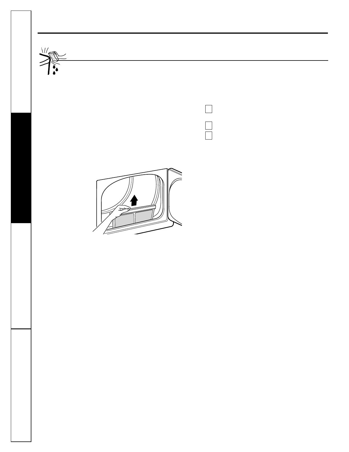
The Lint Filter: Clean the lint filter before each
use. Run your fingers
across the back of the filter
to remove lint.
Do not operate the dryer without
the lint filter in place.
Have a qualified technician vacuum the lint from
the dryer once a year.
The Exhaust Duct: Inspect and clean the exhaust
ducting at least once a year to prevent clogging.
A partially clogged exhaust can lengthen the
drying time.
Follow these steps:
Turn off electrical supply by disconnecting the
plug from the wall socket.
Disconnect the duct from the dryer.
Vacuum the duct with the hose attachment and
reconnect the duct.
The Exhaust Hood: Check with a mirror that the
inside flaps of the hood move freely when operating.
Make sure that there is no wildlife (birds, insects,
etc.) nesting inside the duct or hood.
3
2
1
Care and Cleaning of the Dryer
Customer Service
Care and Cleaning Safety InstructionsInstallation Instructions
Care and cleaning.

7
Read these instructions completely and carefully.
WARNING
■ This dryer must be exhausted to the outdoors
using only rigid metal or flexible metal 4″
diameter ductwork for inside the dryer cabinet
or exhausting.
■ Never use plastic or other combustible ductwork.
See Exhausting section.
■ This appliance must be properly grounded
and installed as described in these Installation
Instructions.
■ Do not install or store appliance in an area where
it will be exposed to water/weather. See Location
of Your Dryer section.
■ The National Fuel Gas code restricts installations
of gas appliances in garages. They must be 18″
(45.7 cm) off the ground and protected from
vehicles by a barrier. See Location of Your Dryer
section.
■ The electrical service to the dryer must conform
with local codes and ordinances and the latest
edition of the National Electrical Code,
ANSI/NFPA 70.
■ The gas service to the dryer must conform
with local codes and ordinances or the latest
edition of the National Fuel Gas Code ANSI
Z223.1. The gas dryer is designed for use under
ANSI Z 21.5.1. This dryer is not recommended
for commercial applications such as restaurants
or beauty salons, etc.
Customer ServiceCare and Cleaning
Safety Instructions Installation Instructions
Preparing to install your dryer.
Phillips head screwdriver
Adjustable pliers
Carpenter’s level
Flat or straight blade screwdriver
Duct tape
Rigid or flexible metal 4″ (10.2 cm) duct
Vent hood
Pipe thread sealer (GAS DRYER)
Tools and Materials Required for Dryer Installation
Prepare the area and exhaust for installation
of the new dryer.
Check to be sure that the existing external
exhaust is clean and that it meets attached
installation specifications.
Using the four shipping carton corner posts
as padding (two on each side), carefully lay
the dryer on its left side and remove foam
shipping pad.
CAUTION: To prevent damage,
do not use the control panel as a means
to pick up or move the dryer.
Return the dryer to an upright position.
Move the dryer to the desired location.
Connect the external exhaust.
Adjust the leveling legs to match the washer
height. The dryer must be level and rest
firmly on all four leveling legs.
Connect the power supply.
Check the operation of the power supply
and venting.
Place the Owner’s Manual and the
Installation Instructions in a location where
they will be noticed by the owner.
10
9
8
7
6
5
4
3
2
1
Preparing the Installation Site and Unpacking the Dryer
Foam shipping pad
Packing

Electrical requirements.
Read these instructions completely and carefully.
Electrical Connection Information for Gas Dryers
WARNING—
To reduce the risk of
fire, electric shock or personal injury:
• DO NOT USE AN EXTENSION CORD OR AN ADAPTER
PLUG WITH THIS APPLIANCE.
•
DO NOT, UNDER ANY CIRCUMSTANCES, CUT OR
REMOVE THE THIRD GROUNDING PRONG FROM
THE POWER CORD.
This dryer
must be electrically grounded in
accordance with local codes and ordinances, or in
the absence of local codes, in accordance with the
NATIONAL ELECTRICAL CODE, ANSI/NFPA NO. 70.
Electrical Requirements
• This dryer must be supplied with 120V, 60 Hz,
and connected to an individual properly
grounded branch circuit, protected by a 15- or
20-amp circuit breaker or time-delay fuse.
• If the electric supply provided does not meet the
above specifications, it is recommended that a
licensed electrician install an approved outlet.
External Ground (if required)
An external ground wire, (not provided), which meets
local codes, may be added by attaching it to the green
ground screw on the rear of the dryer in the upper left
corner above the cord and to grounded metal cold
water pipe or other established ground.
NOTE: A wiring diagram is located inside the
control panel.
Electrical Connection Information for Electric Dryers
WARNING—
To reduce the risk of
fire, electric shock or personal injury:
• DO NOT USE AN EXTENSION CORD WITH THIS
APPLIANCE.
• THIS APPLIANCE MUST BE PROPERLY GROUNDED.
This dryer must be electrically grounded in
accordance with local codes and ordinances,
or in the absence of local codes, in accordance with
the NATIONAL ELECTRICAL CODE, ANSI/NFPA NO. 70.
Electrical Requirements
• This dryer must be connected to a 208V or 240V
individual branch circuit, protected by 30-amp
circuit breakers or time-delay fuses.
• Use copper conductors only.
• If the electric supply does not meet the above
specifications, call a licensed electrician.
NOTE: A wiring diagram is located inside the
control panel.
Ensure proper ground
exists before use
Attach ground wire
(obtain locally)
8
Customer Service
Care and Cleaning Safety InstructionsInstallation Instructions
9
If all rigid metal duct cannot be used, then flexible
all-metal venting can be used, but it will reduce the
maximum recommended duct length. In special
installations when it is impossible to make a
connection with the above recommendations, then
UL-listed clothes dryer transition duct may be used as
transition venting between the dryer and wall
connection only. The use of this ducting will affect
drying time.
If flexible transition duct is necessary, only UL-listed
duct identified for use with clothes dryers is approved.
The following directions must be followed.
• Use the shortest length possible.
• Stretch the duct to its maximum length.
• Do not crush or collapse.
• Never use transition duct inside the wall, flooring,
ceiling or inside the dryer.
• Avoid resting the duct on sharp objects.
• Venting must conform to local building codes.
Exhausting the dryer.
Exhaust System Requirements
Use only 4″ (10.2 cm) diameter (minimum) rigid metal
duct for best performance, or flexible metal duct. Use
approved vent hood which has swing-out dampers
that open when the dryer is in operation. When the
dryer stops, the dampers automatically close to
prevent drafts and the entrance of insects and
rodents. To avoid restricting the outlet, maintain a
minimum of 12″ (30.5 cm) clearance between the
vent hood and the ground or any other obstruction.
If all rigid metal duct cannot be used, then flexible
all-metal venting can be used, but it will reduce the
maximum recommended duct length. See
Additional Installation Instructions following.
WARNING: The following are specific
requirements for proper and safe operation of your
dryer. Failure to follow these instructions can
create excessive drying times and fire hazards.
DO NOT use plastic flexible duct to exhaust the
dryer. Excessive lint can build up inside exhaust
system and create a fire hazard and restrict air
flow. Restricted air flow will increase drying
times. If your present system is made up of plastic
duct or metal foil duct, replace it with rigid or
flexible metal duct. Ensure the present duct is
free of any lint prior to installing dryer duct.
The dryer exhaust system MUST BE EXHAUSTED
TO THE OUTSIDE.
DO NOT allow combustible materials (for
example: clothing, draperies/curtains, paper)
to come in contact with exhaust system.
The dryer MUST NOT be exhausted into a gas vent,
chimney, a wall, a ceiling, a common duct with a
kitchen exhaust or any concealed space of a
building which can accumulate lint, resulting in
a fire hazard.
DO NOT exceed the length of duct pipe or
number of elbows allowed in the Maximum
Length charts. Lint can accumulate in the
exhaust system, plugging the system and
creating a fire hazard, as well as increasing
drying times.
DO NOT screen the exhaust ends of the vent
system, nor use any screws or rivets to assemble
the exhaust system. Lint can become caught
in the screen, on the screws or rivets, clogging
the duct work and creating a fire hazard as
well as increasing drying times. Use an
approved vent hood to terminate the duct
outdoors, and seal all joints with duct tape.
All male duct pipe fittings MUST be installed
downstream with the flow of air.
EXPLOSION HAZARD. Do not install the dryer
where gasoline or other flammables are kept
or stored. If the dryer is installed in a garage,
it must be a minimum of 18″ (45.7 cm) above
the floor. Failure to do so can result in death,
explosion, fire or burns.
Provide an access for inspection and cleaning
of the exhaust system, especially at turns.
Inspect and clean at least once per year.
Do not obstruct incoming or exhausted air.
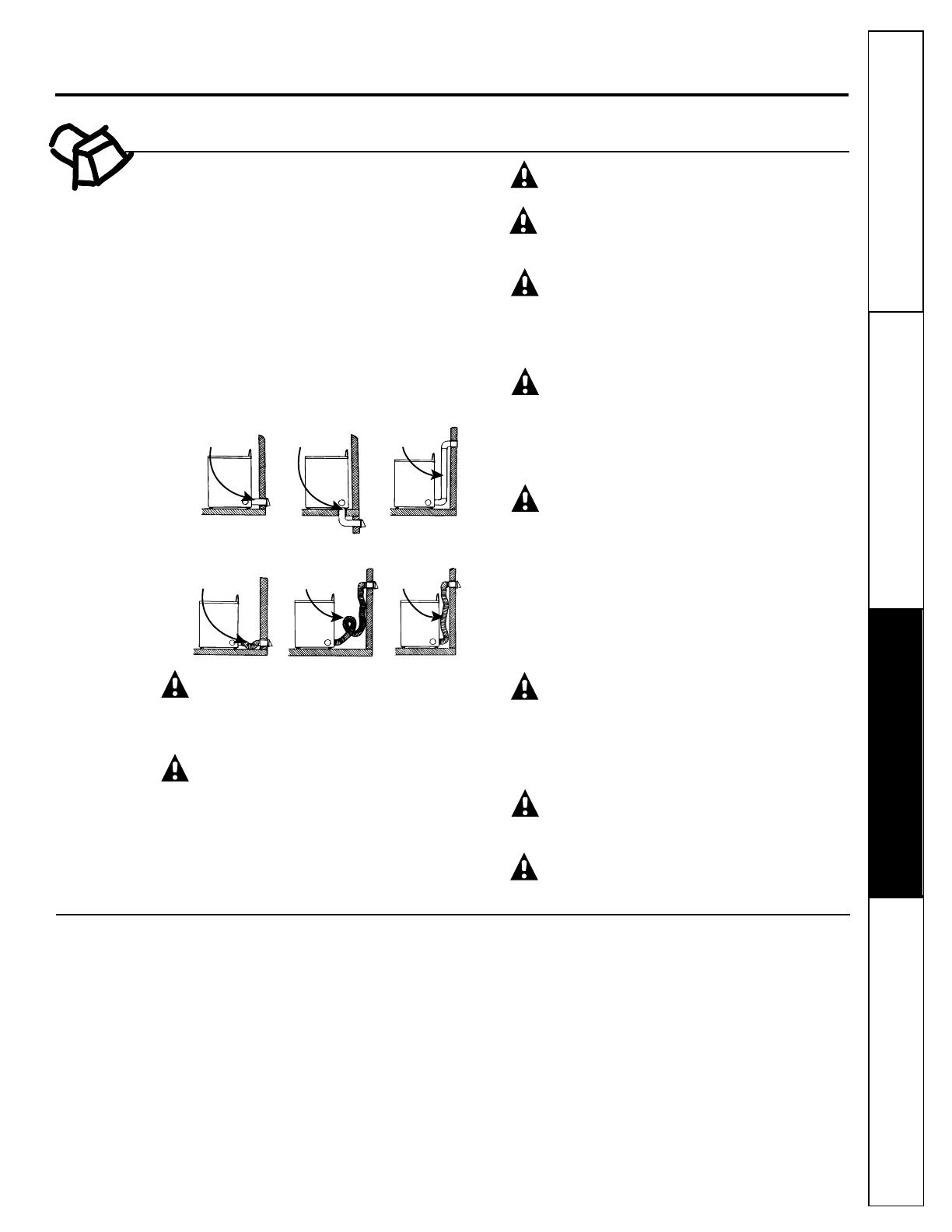
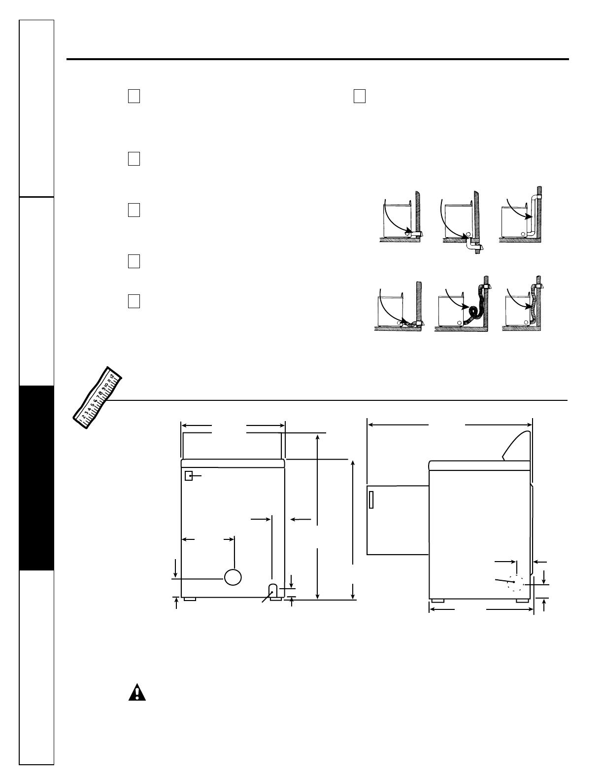
Correct
Incorrect
Do
Do
Do
Don’t
Don’t
Don’t
Additional Ducting Instructions
Customer ServiceCare and CleaningSafety Instructions Installation Instructions
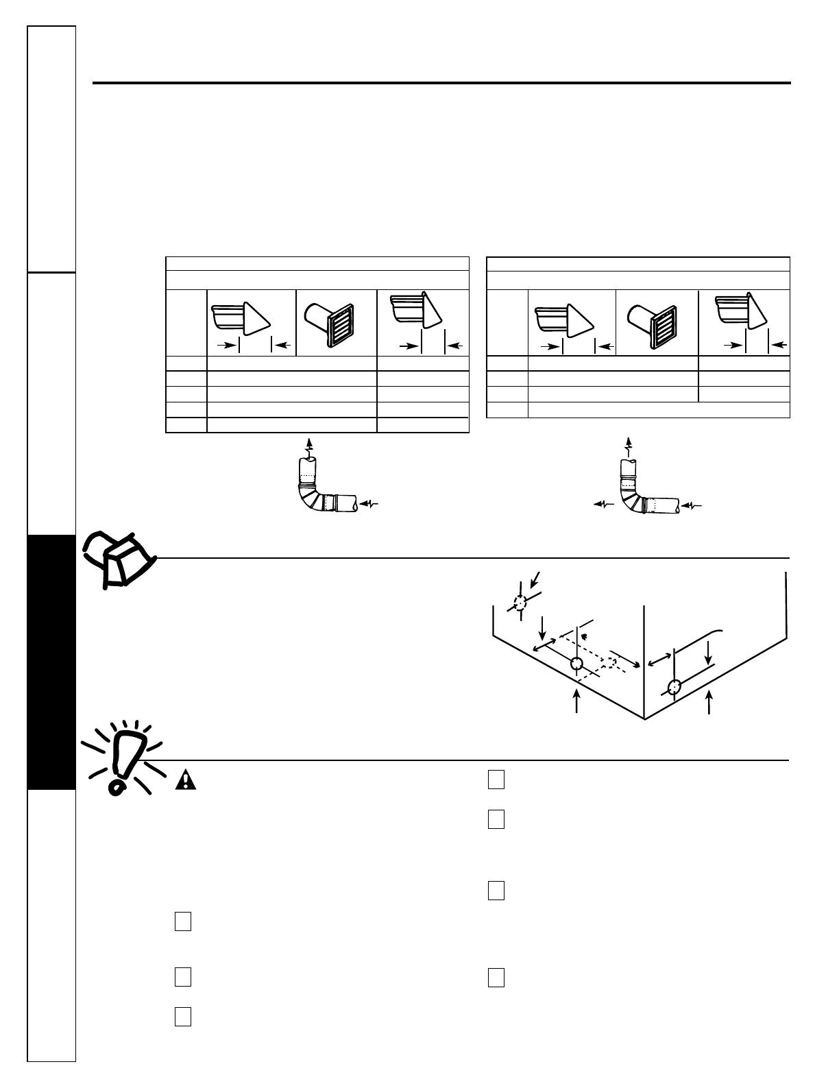
MAXIMUM LENGTH of 4“ (10.2 cm) Dia.
FLEXIBLE METAL DUCT
PREFERRED VENT HOOD TYPE
0 30’ (9.14 m) 18’ (5.49 m)
1 22’ (6.71 m) 14’ (4.27 m)
2 14’ (4.27 m) 10’ (3.05 m)
3 not recommended
Replace brass connecting pipe that is not
plastic-coated. Stainless steel or plastic-coated
brass MUST be used.
WARNING: Never reuse old flexible
connectors. The use of old flexible connectors
can cause gas leaks and personal injury. Always
use NEW flexible connectors when installing a
gas appliance.
Installation MUST conform with local codes, or in
the absence of local codes, with the National
Fuel Gas Code, ANSI Z223.1 (latest edition).
The gas supply line should be of 1/2″ (1.27 cm)
rigid pipe.
If codes allow, flexible metal tubing may be used
to connect your dryer to the gas supply line. The
tubing MUST be constructed of stainless steel or
plastic-coated brass.
The gas supply line MUST have an individual
shutoff valve.
A 1/8″ (0.32 cm) NPT minimum plugged
tapping, accessible for test gauge connection,
MUST be installed immediately upstream of the
gas supply connection to the dryer.
The dryer and its individual shutoff valve MUST
be disconnected from the gas supply piping
system during any pressure testing of the gas
supply piping system at test pressures in excess
of 1/2 psig (3.45 kPa).
The dryer MUST be isolated from the gas supply
piping system by closing its individual manual
shutoff valve during any pressure testing of the
gas supply piping system at test pressures equal
to or less than 1/2 psig (3.45 kPa).
7
6
5
4
3
2
1
Installing the dryer.
Exhaust Direction
All dryers are shipped set up for rear exhausting.
On electric dryers, exhausting can be on the cabinet
right or left side, or through the dryer bottom.
Gas dryers can exhaust on the cabinet right side or
the dryer bottom. To change exhaust direction you
will need Exhaust Kit Pub. No. 14-A018 and a rigid
metal 4″ 90-degree elbow. The kit is available through
your GE retailer. Follow the instructions supplied
with the kit.
Gas Supply Requirements
MAXIMUM LENGTH of 4“ (10.2 cm) Dia. RIGID METAL DUCT
PREFERRED VENT HOOD TYPE
0 60’ (18.28 m) 48’ (14.63 m)
1 52’ (15.84 m) 40’ (12.19 m)
2 44’ (13.41 m) 32’ (9.75 m)
3 32’ (9.75 m) 24’ (7.31 m)
4 28’ (8.53 m) 16’ (4.87 m)
Exhaust Ducting Length
The exhaust system should be inspected and cleaned
at least once a year with normal usage. The more the
dryer is used, the more often you should check the
exhaust system and vent hood for proper operation.
If roof vents or louvered plenums are used, they must
be equivalent to a 4″ dampered wall cap in regard to
resistance to airflow, prevention of back drafts and
maintenance required to prevent clogging.
• DO NOT assemble the duct work with fasteners that
extend into the duct. They will serve as collection
points for lint.
• Ductwork which runs through an unheated area or
is near an air conditioning duct should be
insulated to reduce condensation and lint build-up.
4” (10.2 cm) Louvered
4”
(10.2 cm)
Number of
90° turns
2.5”
(6.35
cm)
4” (10.2 cm) Louvered
4”
(10.2 cm)
Number of
90° turns
2.5”
(6.35
cm)
CORRECT
INCORRECT
INSTALL MALE FITTINGS IN
CORRECT DIRECTION
Same as
other side
EXHAUST DUCT LOCATING
DIMENSIONS
3 3/4″ (9.5 cm)
3 3/4″ (9.5 cm)
13 1/2″
(34 cm)
4 3/8″
(11 cm)
5 7/8″
(15 cm)
10
Customer Service
Care and Cleaning Safety InstructionsInstallation Instructions
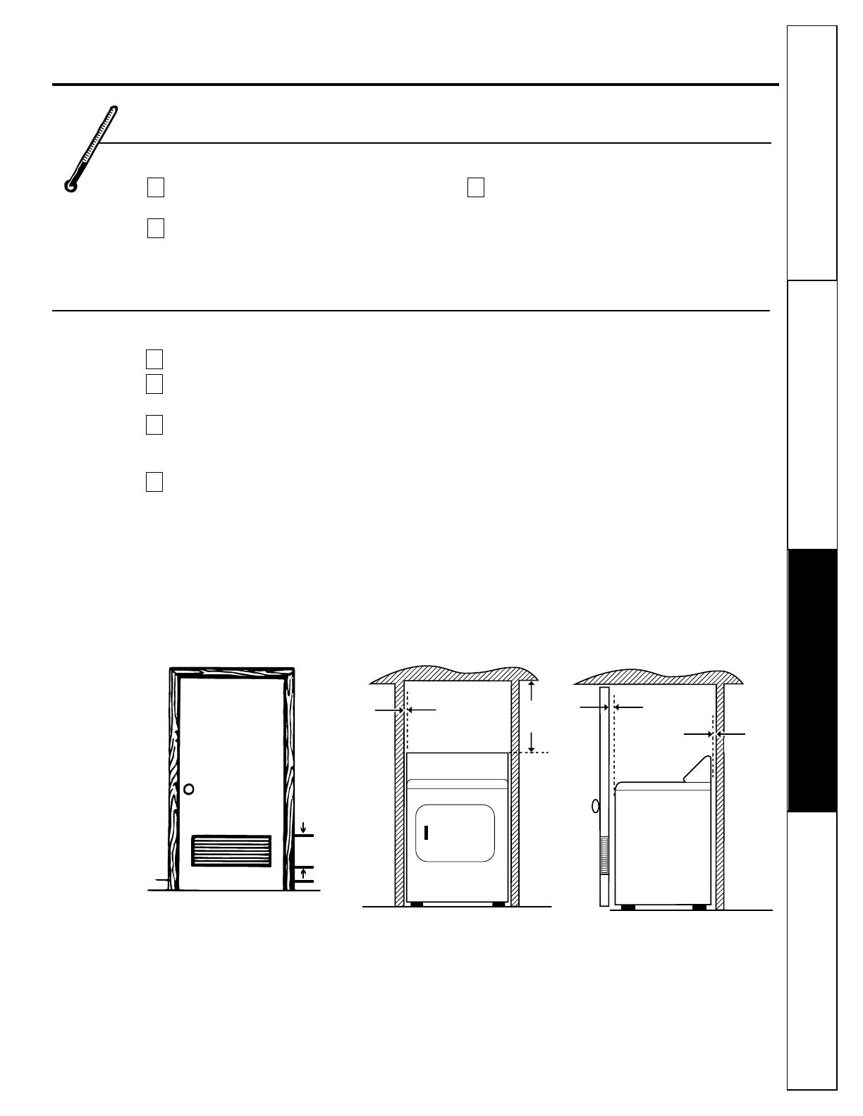
Installation in Recess or Closet
This dryer MUST be exhausted outdoors.
No other fuel burning appliance shall be
installed in the same closet as the GAS DRYER.
Your dryer needs the space around it for
proper ventilation. DO NOT INSTALL YOUR
DRYER IN A CLOSET WITH A SOLID DOOR.
Closet doors must be louvered or otherwise
ventilated and must contain a minimum of
60 sq. in. of open area equally distributed.
If the closet contains both a washer and a dryer,
doors must contain a minimum of 120 sq. in. of
open area equally distributed. Air openings are
required to be unobstructed when a door is
installed. A louvered door with equivalent air
openings for the full length of the door is
acceptable.
Allow the following clearances for ease of installation:
FRONT SIDES REAR* TOP
1″ (2.54 cm) 0 (0 cm) 1″ (2.54 cm) 15″ (38.1 cm)
* Additional rear clearance may be required depending
on the ducting installation.
4
3
2
1
0" (0 cm)
1" (2.54 cm)
15"
(38.1 cm)
60 sq. in.
(387.1 sq. cm)
Closet door
11
Location of Your Dryer
Do Not Install the Dryer:
Do not install the dryer in an area exposed to
dripping water or outside weather conditions.
Do not install the dryer in an area where it will
come in contact with curtains, drapes, or
anything that will obstruct the flow of
combustion and ventilation air.
Do not install the dryer on carpet.
Floor MUST be solid with a maximum slope
of 1″ (2.54 cm).
3
2
1
1" (2.54 cm)
Customer Service
Care and Cleaning
Safety Instructions Installation Instructions
Installing the dryer.
Rough-In Dimensions
Dryer MUST be exhausted outside (outdoors,
not beneath the mobile home) using metal
ducting that will not support combustion. Metal
ducting must be 4″ (10.16 cm) in diameter with
no obstructions. Rigid metal duct is preferred.
If dryer is exhausted through the floor, the
exhaust system must NOT terminate beneath
the mobile home. Termination MUST be
securely fastened to the mobile home structure.
When installing a gas dryer into a mobile home,
a provision must be made for outside make-up
air. This provision is to be not less than twice the
area of the dryer exhaust outlet.
Gas dryers MUST be fastened to the floor
using Mobile Home Installation Kit Pub.
No. 14-D346-33.
See the Exhaust System Requirements section
for other important venting information.
Installation MUST conform to current
Manufactured Home Construction & Safety
Standard (which is a Federal Regulation Title
24 CFR—Part 32–80) or, when such standard
is not applicable, with American National
Standard for Mobile Homes, ANSI/NFPA
No. 501B.
The dryer is designed for use under ANSI Z 21.5.1.
6
5
4
3
2
1
Mobile Home Installation
26 7/8″
(68.3 cm)
47 1/2″
(120.7 cm)
43 5/8″
(110.7 cm)
2 9/16″
(6.5 cm)
13 1/2″
(34.4 cm)
36″
(91.5 cm)
Door open
90˚
4 3/8″
(11.1 cm)
Optional
vent knockout
27″
(68.6 cm)
Electrical connection
3/8″ (0.96 cm) Dia.
gas pipe
1″ (2.54 cm)
3 3/4″
(9.5 cm)
3 3/4″
(9.5 cm)
REAR VIEW
SIDE VIEW
Correct
Incorrect
Do
Do
Do
Don’t
Don’t
Don’t
Servicing – Consideration must be given to provide adequate clearances for installation and servicing.
CAUTION: Label all wires prior to disconnection when servicing controls. Wiring errors can
cause improper and dangerous operation (verify proper operation after servicing/installation).
12
Customer Service Care and Cleaning Safety InstructionsInstallation Instructions
13
Electrical Installation for Electric Dryers
WARNING: The following are specific
requirements for proper and safe electrical
installation of your dryer. Failure to follow
these instructions can create electrical shock
and/or a fire hazard.
WARNING: This appliance MUST be
properly grounded. Electrical shock can result
if the dryer is not properly grounded. Follow
the instructions in this manual for proper
grounding.
WARNING: DO NOT use an extension
cord with this dryer. Some extension cords are
not designed to withstand the amounts of
electrical current this dryer utilizes and can
melt, creating electrical shock and/or fire
hazard. Locate the dryer within reach of the
wall outlet, taking into account the length
of power cord to be purchased and allowing
some slack in the cord. Refer to Electrical
Requirements in this manual for the proper
power cord to be purchased.
WARNING: A UL-listed strain relief
must be installed onto power cord. If the
strain relief is not attached, the cord can be
pulled out of the dryer and can be cut by any
movement of the cord, resulting in electrical
shock.
WARNING:Use copper receptacles
only.
NOTE: Dryers operating on 208-volt power supply
will have longer drying times than those operating
on 240-volt power supply.
A wiring diagram is located inside the control panel.
Grounding Requirements
WARNING: Improper connection of
the equipment-grounding conductor can result in
a risk of electric shock. Check with a licensed
electrician if you are in doubt as to whether the
appliance is properly grounded.
Grounding must be in accordance with local codes
and ordinances, or in the absence of local codes,
in accordance with the National Electrical Code
ANSI/NFPA No. 70.
For a grounded, cord-connected electric dryer:
The dryer MUST be grounded. In the event of
a malfunction or breakdown, grounding will
reduce the risk of electrical shock by creating
a path of least resistance for electrical current.
If your dryer is equipped with a power supply
cord having an equipment-grounding
conductor and a grounding plug, the plug
MUST be plugged into an appropriate, copper-
wired receptacle that is properly installed and
grounded in accordance with all local codes
and ordinances. If in doubt, call a licensed
electrician.
For a permanently-connected electric dryer:
■ The dryer MUST be connected to a grounded
metal, permanent wiring system; or an
equipment-grounding conductor must be run
with the circuit conductors and connected to
the equipment-grounding terminal or lead on
the appliance.
For a cord-connected gas dryer:
■ This dryer is equipped with a three-prong
(grounding) plug for your protection against
shock hazard and should be plugged directly
into a properly grounded three-prong receptacle.
Do not modify plug provided with the appliance:
if it will not fit the outlet, have a proper outlet
installed by a qualified electrician.
2
1
Customer Service
Care and Cleaning
Safety Instructions Installation Instructions
Remove the screws securing the terminal block
access cover and the strain relief mounting
bracket located on the back of the dryer upper
corner.
Install a UL-listed strain relief into the power
cord entry hole of the mounting bracket. Use
a strain relief which attaches to the mounting
bracket with a nut. Finger-tighten the nut only
at this time.
Thread a UL-listed 30A, 240V, 3 #10 AWG
minimum copper conductor power cord through
the strain relief. Power cord leads to be
terminated with open-end spade lugs with
upturned ends.
Attach the power cord neutral (center wire)
conductor to the silver-colored center terminal
on the terminal block. Tighten the screw
securely.
Attach the remaining two power cord outer
conductors to the outer brass-colored terminals
on the terminal block. Tighten both screws
securely.
WARNING: Do not make a sharp
bend or crimp wiring/conductor at
connections.
Reattach the strain relief mounting bracket to
the back of the dryer with one screw. Tighten
screw securely.
Tighten the screws securing the cord restraint
firmly against the power cord.
Tighten the strain relief nut securely so that the
strain relief does not turn.
Reinstall the terminal block access cover.
9
8
7
6
5
4
3
2
1
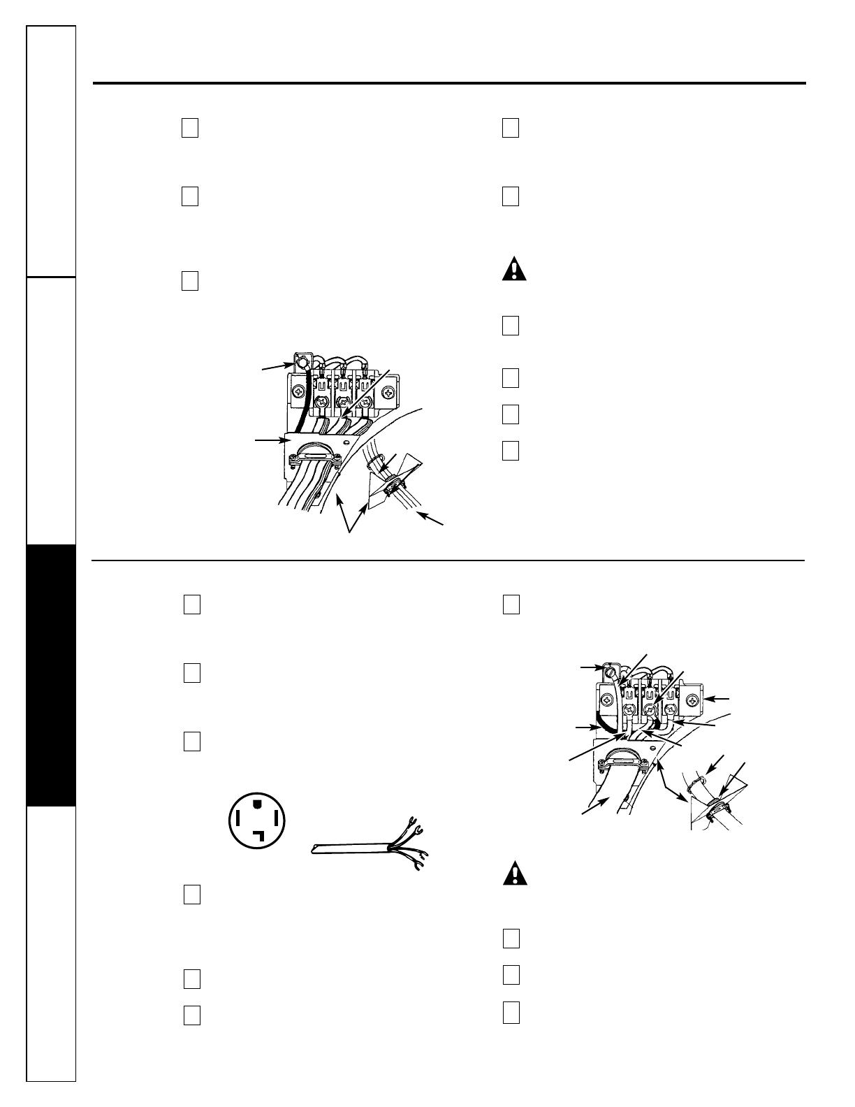
3-Wire System for Electric Dryers—DO NOT use for Mobile Home Installations
Installing the dryer.
4-Wire System for Electric Dryers—MUST be used for Mobile Home Installations
Remove the screws securing the terminal block
access cover and the strain relief mounting
bracket located on the back of the dryer upper
corner.
Install a UL-listed strain relief in the entry hole
of the mounting bracket. Use a strain relief
which attaches to the mounting bracket with
a nut. Finger-tighten the nut only at this time.
Remove the green neutral ground wire from
the green ground screw located above the
terminal block.
Thread a UL-listed 30A, 240V, 4 #10 AWG
minimum copper conductor power cord
through
the strain relief. Power cord leads to
be terminated with open-end spade lugs with
upturned ends.
Attach the green power cord ground wire to
the cabinet with the green ground screw.
Attach the white (neutral) power cord
conductor from the power cord and the green
ground wire from the dryer harness to the silver-
colored center terminal on the terminal block.
Tighten the screw securely.
Attach the red and black power cord
conductors to the outer brass-colored terminals
on the terminal block.
WARNING: Do not make a sharp
bend or crimp wiring/conductor at the
connections.
Tighten the screws securing the cord restraint
firmly against the power cord.
Tighten the strain relief nut securely so the
strain relief does not turn.
Reinstall the terminal block access cover.
10
9
8
7
6
5
4
3
2
1
Green ground screw
Silver terminal
Nut
Tighten nut to
these threads
Power cord
Strain relief
mounting bracket
Green neutral
ground wire
Green ground
screw
Green neutral
ground wire
Red
White
Black
Terminal block
Silver terminal
Green power cord ground wire
Nut
Tighten nut to
these threads
Power cord
Strain
relief
mounting
bracket
Typical 4-
conductor
receptacle
Black 240V
White neutral
Red 240V
Green ground
Typical
4-conductor cord
Use copper
conductors only.
14
Customer Service Care and Cleaning
Safety Instructions
Installation Instructions
15
Replacement Parts
If replacement parts are needed for your dryer,
contact the source where you purchased your dryer.
CAUTION: Label all wires prior to
disconnection when servicing controls. Wiring
errors can cause improper and dangerous
operation. Verify proper operation after
servicing.
WARNING: Destroy the carton and
plastic bags after the parts are unpacked.
Children might use them for play. Cartons
covered with rugs, bedspreads or plastic sheets
can become airtight chambers causing
suffocation. Place all materials in a garbage
container or make materials inaccessible
to children.
WARNING: The instructions in the
manual and all other literature included with
this dryer are not meant to cover every possible
condition and situation that may occur. Good
safe practice and caution MUST be applied
when installing, operating and maintaining
any appliance.
Gas Connection for Gas Dryers
Remove the shipping cap from gas pipe at the
rear of the dryer.
NOTE: DO NOT connect the dryer to LP gas service
without converting the gas valve. An LP conversion
kit (Pub. No. 14-A038) MUST be installed by a
qualified gas technician.
Connect a 1/2″ (1.27 cm) I.D. semi-rigid
or approved pipe from gas supply line to
the 3/8″ (0.96 cm) pipe located on the back
of the dryer. Use a 1/2″ to 3/8″ (1.27 cm to
0.96 cm) reducer for a connection. Apply an
approved thread sealer that is resistant to the
corrosive action of liquefied gases on all pipe
connections.
Open the shutoff valve in the gas supply line.
Test all connections by brushing on a soapy
water solution.
WARNING:NEVER TEST FOR GAS
LEAKS WITH AN OPEN FLAME.
NOTE: On gas dryers, before the burner will light,
it is necessary for the gas line to be bled of air.
If the burner does not light within 45 seconds the
first time the dryer is turned on, the safety switch
will shut the burner off. If this happens, turn the
dryer off and wait 5 minutes before making another
attempt to light.
4
3
2
1
Before Operating the Dryer
Connect the exhaust duct to outside exhaust
system. Use duct tape to seal all joints.
With the dryer in its final position, adjust one or
more of the legs until the dryer is resting solidly
on all four legs. Place a level on top of the dryer.
THE DRYER MUST BE LEVEL AND RESTING
SOLIDLY ON ALL FOUR LEGS.
Plug the power cord into a grounded outlet.
NOTE: Check to ensure the power is off at circuit
breaker/fuse box before plugging the power
cord into the outlet.
Turn on the power at the circuit breaker/fuse
box.
CAUTION: Before operating the
dryer, make sure the dryer area is clear and
free from combustible materials, gasoline,
and other flammable vapors. Also see that
nothing (such as boxes, clothing, etc.)
obstructs the flow of combustion and
ventilation air.
Run the dryer through a cycle check for proper
operation.
Place these instructions in a location near the
dryer for future reference.
6
5
4
3
2
1
Customer Service
Care and CleaningSafety Instructions
Installation Instructions

Installing the dryer.
Reversing the Dryer Door Swing
Open the dryer door. Remove the 4 hinge
hole plugs or screws from the left side of door
opening. Place nearby for future installation.
NOTE: You may need a plastic knife to help pull
out the plugs. Be careful not to scratch the paint.
Remove the four screws that secure the door
hinges to the dryer front panel. NOTE: Remove
1 screw from each of the 2 hinges first. Hold the
door firmly before removing the last 2 screws.
Rotate the door 180° and reinstall the door
hinges to the dryer front panel with the
4 screws.
Install the 4 hinge hole plugs or screws that
were removed in step 1 into the open screw
holes on the right side of the door opening.
4
3
2
1
Remove 4 screws—one from each hinge first
16
Customer Service
Care and Cleaning Safety InstructionsInstallation Instructions

17
Countdown Display (DCD models only)
The countdown display shows the remaining
operating time as well as the current drying cycle.
The display board is configured for a 45-minute
dry time at the factory to correspond with the
45-minute timer cam pre-installed in the coin box.
If the timer cam is modified for another operating
duration, the dip switches on the display board
should be set as follows:
NOTE: This display does not accumulate time. See the following examples of display possibilities.
DIP SWITCH NUMBERS
DRYING TIME (minutes) 1 2
45 1 1
60 1 0
90 0 1
120 0 0
Customer Service
Care and CleaningSafety Instructions Installation Instructions
DIP SWITCH SETTING (min) COIN SLIDE ACTUATIONS DISPLAY READING (min)
45 1 45 to 0, then blank
45 2 45 to 1, then 1 for next 45 min.,
then 0 and blank
120 1 99 for 21 minutes, then 98 to 0,
then blank
18
Customer Service
Care and Cleaning Safety InstructionsInstallation Instructions
GE Commercial Dryer Warranty.
Parts and service are available from your General Electric
Commercial Laundry distributor.
For The Period Of: We Will Replace:
Three Years Any part of the dryer which fails due to a defect in materials or workmanship. During this
From the date of the limited three-year warranty, you will be responsible for any labor and related service costs.
original purchase
Five Years The dryer drum, if it should fail due to a defect in materials or workmanship, and the cabinet side
From the date of the panels, base and cover, if they should fail due to rust-through. During this limited additional two-
original purchase year warranty, you will be responsible for any labor and related service costs.
■ Coin drop meter, coin slide mechanism, coin vault and
locks, smart card modules and cards, smart card system
accessories.
■ Service trips to your place of business to teach you how
to use the product.
■ Improper installation.
■ Failure of the product if it is abused, misused, or used
for other than the intended purpose.
■ Any and all implied warranties of merchantability and
fitness for a particular purpose.
■ Replacement of fuses or resetting of circuit breakers at
place of business.
■ Damage to the product caused by accident, fire, floods or
acts of God.
■ Incidental or consequential damage caused by possible
defects with this appliance.
This warranty is extended to the original purchaser and any succeeding owner for products purchased for
commercial use within the USA. In Alaska, the warranty excludes the cost of shipping to your place of business.
Some states do not allow the exclusion or limitation of incidental or consequential damages. This warranty gives
you specific legal rights, and you may also have other rights which vary from state to state. To know what your
legal rights are, consult your local or state consumer affairs office or your state’s Attorney General.
Warrantor: General Electric Company. Louisville, KY 40225
What Is Not Covered:
Staple your receipt here.
Proof of the original purchase
date is needed to obtain service
under the warranty.

19
AUTOMATIC DRYER
COMMERCIAL APPLICATION
GENERAL ELECTRIC DRYERS
GENERAL PRINCIPLES OF GOOD PRACTICE
(COIN-OPERATED MODELS ONLY)
In fulfilling the specific needs of different commercial installations, the purchaser of this
General Electric automatic dryer may wish to locate the coin box and controls in any of
a number of locations. The responsibility for the proper performance of this work lies
solely with the purchaser. It should be done by properly trained and qualified personnel,
and in accordance with local code requirements.
In addition, General Electric Company assumes no responsibility or liability whatsoever to
the purchaser for any patent infringement expenses, either in the form of damages or legal
costs, where the alleged infringement is based on a patent claim including one or more
components added by the purchaser (i.e., not supplied by General Electric Company with
the purchased dryer).
Set forth below are some general principles which should be followed by persons installing
the coin box and controls in the desired location. This listing is not all-inclusive, and is
only intended to serve as a general guide. These principles are intended to supplement,
not modify, the Installation Instructions which accompany the automatic dryer.
1. Any component added to the automatic dryer, either electrically or mechanically,
should be properly grounded.
2. All current-carrying metal parts should be isolated from possible contact by the user.
3. All wiring should be properly protected from sharp edges, burrs, moving parts and other
agencies which might cause abrasion of the insulation on the conductors.
4. All electrical connections should be mechanically secure, and should provide adequate
and reliable electrical contact under conditions, such as vibration, to which they may be
subjected.
5. All electrical components, wires, and terminals should be of proper electrical rating for
the specific application.
6. All insulating materials should remain effective under the specific conditions to which
they will be exposed (e.g., humidity, temperature, etc.).
7. The installation should not be incompatible with the electrical circuit within the
automatic dryer nor in any manner interfere with either the safety devices or the
sequence of operations of the cycle which are engineered into the appliance.
8. Uninsulated current-carrying metal parts should have adequate and ensured permanence
of spacing from other parts.

Printed in the United States
Consumer Support.
GE Appliances Website
GEAppliances.com
Have a question or need assistance with your appliance? Try the GE Appliances Website 24 hours a day,
any day of the year! For greater convenience and faster service, you can now download Owner’s Manuals,
order parts, catalogs, or even schedule service on-line. You can also “Ask Our Team of Experts
™
”
your questions, and so much more...
Schedule Service GEAppliances.com
Expert GE repair service is only one step away from your door. Get on-line and schedule your service at
your convenience 24 hours any day of the year! Or call 800.GE.CARES (800.432.2737) during normal
business hours.
Real Life Design Studio GEAppliances.com
GE supports the Universal Design concept—products, services and environments that can be used by
people of all ages, sizes and capabilities. We recognize the need to design for a wide range of physical and
mental abilities and impairments. For details of GE’s Universal Design applications, including kitchen
design ideas for people with disabilities, check out our Website today. For the hearing impaired, please call
800.TDD.GEAC (800.833.4322).
Extended Warranties GEAppliances.com
Purchase a GE extended warranty and learn about special discounts that are available while your warranty
is still in effect. You can purchase it on-line anytime, or call 800.626.2224 during normal business hours.
GE Consumer Home Services will still be there after your warranty expires.
Parts and Accessories GEAppliances.com
Individuals qualified to service their own appliances can have parts or accessories sent directly to their
homes (VISA, MasterCard and Discover cards are accepted). Order on-line today, 24 hours every day or by
phone at 800.626.2002 during normal business hours.
Instructions contained in this manual cover procedures to be performed by any user. Other servicing generally
should be referred to qualified service personnel. Caution must be exercised, since improper servicing may cause
unsafe operation.
Contact Us GEAppliances.com
If you are not satisfied with the service you receive from GE, contact us on our Website with all the details
including your phone number, or write to: General Manager, Customer Relations
GE Appliances, Appliance Park
Louisville, KY 40225
Register Your Appliance GEAppliances.com
Register your new appliance on-line—at your convenience! Timely product registration will allow for
enhanced communication and prompt service under the terms of your warranty, should the need arise.
You may also mail in the pre-printed registration card included in the packing material.
/