LG DLGX4271W Owner's manual
- Category
- Electric laundry dryers
- Type
- Owner's manual
This manual is also suitable for

Life's Good
DRYER
Please read fhis owner's manuat fhoroughty before operafin 9 and keep if
handy for reference af art times,
DLEX4270 _ DLGX4271 _
MFL67731027
wwwAg.com

2 TABLE OF CONTENTS
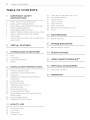
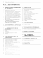
TABLE OF CONTENTS
IMPORTANT SAFETY
INSTRUCTIONS
3 WHAT TO DO IF YOU SMELL GAS
4 BASIC SAFETY PRECAUTIONS
4 CALIFORNIA SAFE DRINKING WATER AND
TOXIC ENFORCEMEN ACT
B GROUNDING INSTRUCTIONS
B SAFETY INSTRUCTIONS FOR INSTALLA]ION
6 SAFETY INSTRUCTIONS FOR STEAM
FUNCTIONS
7 SAFETY INSTRUCTIONS FOR CONNECTING
ELECTRICITY
8 SPECIAL FEATURES
9 INTRODUCING YOUR DRYER
9 Parts
9 Accessories
10 Control Panel Features
11 Display
12 INSTALLATION INSTRUCTIONS
12 Preview Installation Order
13 Installation Location Requirements
13 Clearances
14 Installation with Optional Pedestal Base or
Stacking Kit
1B Leveling the Dryer
16 Reversing the Door
18 Installing the Side Vent Kit
19 Venting the Dryer
21 Connecting Gas Dryers
23 Connecting Electric Dryers
28 Special Requirements for Manufactured or
Mobile Homes
28 Final Installation Check
29 Installation -rest (Duct Check)
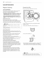
33 Check the Lint Filter before Every Load
34 Cycle Modifier Buttons
35 Special Functions
36 Custom Program
3"6 Steam Functions
38 Steam Cycle Guide
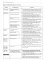
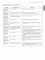
39 Before Using the Tag On Function
40 Tag On
46 MAINTENANCE
46 Regular Cleaning
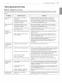
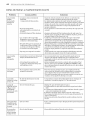
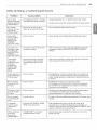
47 TROUBLESHOOTING
47 Before Calling for Service
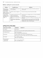
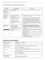
._60 SPECIFICATIONS
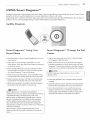
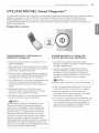
51 USING SMART DIAGNOSIS TM
52 OPTIONAL ACCESSORIES
.52 Stacking Kit Installation
54 WARRANTY
31 HOW TO USE
31 Operating the Dryer
32 Cycle Guide
33 Sorting Load
33 Loading the Dryer

IMPORTANTSAFETYINSTRUCTIONS3
IMPORTANT SAFETY INSTRUCTIONS
READ ALL INSTRUCTIONS BEFORE USE
_WARNING
For your safety, the information in this manual must be followed to minimize the risk of fire or explosion, electric
shock, or to prevent property damage, injury to persons, or death.
f
Your safety and the safety of others is very important,
We have provided many important safety messages in this manual and on your appliance, Always read and obey a
safety messages.
This is the safety alert symbol,
This symbol alerts you to potential hazards that can kill or hurt you and others.
All safety messages will follow the safety alert symbol and either the word DANGER, WARNING, or CAUTION,
These words mean:
_DANGER
You will be killed or seriously injured if you don't immediately follow instructions,
_WARNING
You can be killed or seriously injured if you don't follow instructions,
A_CAUTION
You may be slightly injured or cause damage to the product if you do not follow instructions,
All safety messages will tell you what the potential hazard is,tell you how to reduce the chance of injury, and tell
you what can happen if the instructions are not followed,
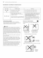
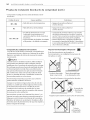
• Do not install a clothes dryer with flexible plastic venting materials. If flexible metal (foil type) duct is
installed, it must be of a specific type identified by the appliance manufacturer as suitable for use with
clothes dryers. Flexible venting materials are known to collapse, be easily crushed, and trap lint. These
conditions will obstruct clothes dryer airflow and increase the risk of fire,
• Do not store or use gasoline or other flammable vapors and liquids in the vicinity of this appliance or any
other appliances.
• Installation and service must be performed by a qualified installer, service agency, or the gas supplier.
• Install the clothes dryer according to the manufacturer's instructions and local codes.
• Save these instructions,
WHAT TO DO IF YOU SMELL GAS:
1. Do not tryto light a match or cigarette, or turn on any gas or electrical appliance.
2, Do not touch any electrical switches. Do not use any phone in your building.
3. Clear the room, building, or area of all occupants.
4. Immediately call your gas supplier from a neighbor's phone. Follow the gas supplier's instructions
carefully.
5. If you cannot reach your gas supplier, call the fire department.
_WARNING:This product contains chemicals known to the State of California to cause cancer and birth defects or
other reproductive harm. Wash hands after handlin 9,

4 IMPORTANT SAFETY INSTRUCTIONS
IMPORTANT SAFETY INSTRUCTIONS
READ ALL INSTRUCTIONS BEFORE USE
_WARNING
For your safety, the information in this manual must be followed to minimize the risk of fire or explosion, electric
shock, or to prevent property damage, injury to persons, or death,
BASIC SAFETY PRECAUTIONS
_WARNING
To reduce the risk of fire, electric shock, or injury to persons when using this appliance, follow basic precautions,
including the following:
• Read all instructions before using the dryer.
• Before use, the dryer must be properly installed as
described in this manual.
• Do not place items exposed to cooking oils in your
dryer. Items contaminated with cooking oils may
contribute to a chemical reaction that could cause
a load to catch fire.
• Do not dry articles that have been previously cleaned
in, washed in, soaked in, or spotted with gasoline, dry-
cleaning solvents, or other flammable or explosive
substances as they give off vapors that could ignite or
explode.
• Do not reach into the dryer if the drum or any other
part ismoving.
• Do not repair or replace any part of the dryer
or attempt any servicing unless specifically
recommended in this owner's manual or in published
user-repair instructions that you understand and have
the skills to carry out.
• Do not tamper with controls.
• Before the dryer is removed from service or discarded,
remove the door to the drying compartment.
. Do not allow children to play on or in the dryer. Close
supervision of children is necessary when the dryer is
used near children.
.Do not use fabric softeners or products to eliminate
static unless recommended by the manufacturer of
the fabric softener or product.
. Do not use heat to dry articles containing foam
rubber or similarly textured rubber-like materials.
.Keep area around the exhaust opening and adjacent
surrounding areas free from the accumulation of lint,
dust, and dirt.
. The interior of the dryer and exhaust vent should be
cleaned periodically by qualified service personnel.
. Do not install or store the dryer where it will be
exposed to the weather.
. Always check the inside of the dryer for foreign
objects.
. Clean lint screen before or after each load.
. Do not store plastic, paper, or clothing that may
burn or melt on top of the dryer during operation.
CALIFORNIA SAFE DRINKING WATER AND TOXIC ENFORCEMENT ACT
This act requires the governor of California to publish a list of substances known to the state to cause cancer, birth
defects, or other reproductive harm and requires businesses to warn customers of potential exposure to such
substances.
Gas appliances can cause minor exposure to four of these substances, namely benzene, carbon monoxide,
formaldehyde, and soot, caused primarily by the incomplete combustion of natural gas or LP fuels.
Properly adjusted dryers will minimize incomplete combustion. Exposure to these substances can be minimized
further by properly venting the dryer to the outdoors.

IMPORTANT SAFETY INSTRUCTIONS 5
IMPORTANT SAFETY INSTRUCTIONS
READ ALL INSTRUCTIONS BEFORE USE
_WARNING
For your safety, the information in this manual must be followed to minimize the risk of fire or explosion, electric
shock, or to prevent property damage, injury to persons, or death,
GROUNDING INSTRUCTIONS
This appliance must be grounded. In the event of
malfunction or breakdown, grounding will reduce
the risk of electric shock by providing a path of least
resistance for electric current. This appliance must be
equipped with a cord having an equipment-grounding
conductor and a grounding plug. The plug must be
plugged into an appropriate outlet that is properly
installed and grounded in accordance with all local
codes and ordinances.
_WARNING
Do not modify the plug provided with the appliance. If
it will not fit the outlet, have a proper outlet installed by
a qualified electrician.
This appliance must be connected to a grounded metal,
)ermanent wiring system or an equipment-grounding
conductor must be run with the circuit conductors and
connected to the equipment-grounding terminal or
lead on the appliance.
Electric shock can result if the dryer is not properly
grounded.
Improper connection of the equipment-grounding conductor can result in a risk of electric shock. Check with a
qualified electrician or service person if you are in doubt that the appliance is properly grounded.
SAFETY iNSTRUCTiONS FOR iNSTALLATiON
_WARNING
To reduce the risk of fire, electric shock, or injury to persons when using this appliance, follow basic precautions,
including the following:
• Properly ground dryer to conform with all
governing codes and ordinances. Follow details in
the installation instructions. Electric shock can result if
the dryer is not properly grounded.
• Before use, the dryer must be properly installed as
described in this manual. Electric shock can result if
the dryer is not properly grounded.
• InstaJl and store the dryer where it wiff not be
exposed to temperatures below freezing or
exposed to the weather.
• Aft repairs and servicing must be performed
by an authorized servicer unless specifically
recommended in this owner's manual. Use only
authorized factory parts. Failure to follow this
warning can cause serious injury, fire, electric shock, or
death.
• To reduce the risk of electric shock, do not install
the dryer in humid spaces. Failure to follow this
warning can cause serious injury, fire, electric shock, or
death.
Remove all packing items and dispose of all
shipping materials properly. Failure to do so can
result in death, explosion, fire, or burns.
Place dryer at least 18 inches above the floor for
a garage instaffation. Failure to do so can result in
death, explosion, fire, or burns.
Keep all packaging from children. Packaging
material can be dangerous for children. There is a risk
of suffocation.
Do not install near another source of heat such as
a stove, cooking oven. Failure to do so can cause
deform, smoke and fire.
Do not place candles, smoking materials, or other
flammables on top of the product. Dripping wax,
smoke, or fire can result.
Remove all protective vinyl film from the product.
Failure to do so can cause product damage, smoke or
fi re.
• Connect to a properly rated, protected, and sized
power circuit to avoid electrical overload. Improper
power circuit can melt, creating electric shock and/or
fire hazard.

6 IMPORTANTSAFETYINSTRUCTIONS
IMPORTANT SAFETY INSTRUCTIONS
READ ALL INSTRUCTIONS BEFORE USE
_WARNING
For your safety, the information in this manual must be followed to minimize the risk of fire or explosion, electric
shock, or to prevent property damage, injury to persons, or death,
SAFETY iNSTRUCTiONS FOR iNSTALLATiON
_WARNING
To reduce the risk of injury to persons, follow all industry recommended safety procedures including the use of long
sleeved gloves and safety glasses. Failure to follow all of the safety warnings in this manual could result in property
damage, injury to persons, or death.
Exhaust/Ducting:
• Gas dryers MUST be exhausted to the outside,
Failure to follow these instructions can result in fire or
death.
• The dryer exhaust system must be exhausted
to the outside of the dwelling. If the dryer is not
exhausted outdoors, some fine lint and large
amounts of moisture wii] be expelled into the
laundry area. An accumulation of lint in any area of
the home can create a health and fire hazard.
• Use only rigid metal or flexible metal 4-inch
diameter ductwork inside the dryer cabinet or for
exhausting to the outside, Use of plastic or other
combustible ductwork can cause a fire. Punctured
ductwork can cause a fire if it collapses or becomes
otherwise restricted in use or during installation.
• Ouctwork is not provided with the dryer, and you
should obtain the necessary ductwork locally. The
end cap should have hinged dampers to prevent
backdraft when the dryer is not in use. Failure to
follow these instructions can result in fire or death.
. The exhaust duct must be 4 inches (10.2 cm) in
diameter with no obstructions. The exhaust duct
should be kept as short as possible. Make sure
to dean any old ducts before installing your new
dryer. Failure to follow these instructions can result in
fire or death.
. Rigid or semi-rigid metal ducting is recommended
for use between the dryer and the wail in special
installations when it is impossible to make a
connection with the above recommendations, a UL-
listed flexible metal transition duct may be used
between the dryer and wall connection only. The
use of this ducting will affect drying time. Failure to
follow these instructions can result in fire or death.
. DO NOT use sheet metal screws or other fasteners
which extend into the duct that could catch lint and
reduce the efficiency of the exhaust system. Secu re
all joints with duct tape. For complete details, follow
the Installation Instructions. Failure to follow these
instructions can result in fire or death.
SAFETY INSTRUCTIONS FOR STEAM FUNCTIONS
_WARNING
To reduce the risk of fire, electric shock, or injury to persons when using this appliance, follow basic precautions,
including the following:
• Do not open the dryer door during steam cycles.
Failure to follow these instructions can result in a burn
hazard.
• Do not dry articles that have been previously
cleaned in, washed in, soaked in, or spotted with
gasoline, dry-cleaning solvents, or other flammable
or explosive substances as they give off vapors
that could ignite or explode, Failure to follow these
instructions can result in fire or death.
. Do not fill the steam feeder with gasoline, dry-
cleaning solvents, or other flammable or explosive
substances. Failure to follow these instructions can
result in fire or death.
. Do not touch the steam nozzle in the drum during
or after the steam cycle. Failure to follow these
instructions can result in a burn hazard.
. Do not fill the steam feeder with hot water (over 86
°F/30 °C), Failure to follow these instructions can result
in a burn hazard.

IMPORTANT SAFETY INSTRUCTIONS 7
IMPORTANT SAFETY INSTRUCTIONS
READ ALL INSTRUCTIONS BEFORE USE
_WARNING
For your safety, the information in this manual must be followed to minimize the risk of fire or explosion, electric
shock, or to prevent property damage, injury to persons, or death,
SAFETY iNSTRUCTiONS FOR CONNECTING ELECTRiCiTY
_WARNING
To reduce the risk of fire, electric shock, or injury to persons when using this appliance, follow basic precautions,
including the following:
. Do not, under any circumstances, cut or remove
the ground prong from the power cord. To prevent
injury to persons or damage to the dryer, the electrical
power cord must be plugged into a properly grounded
outlet.
. For personal safety, this dryer must be properly
grounded. Failure to do so can result in electric shock
or injury.
. Refer to the installation instructions in this manual
for specific electrical requirements for your model.
Failure to follow these instructions can create an
electric shock hazard and/or a fire hazard.
. This dryer must be plugged into a properly
grounded outlet. Electric shock can result if the
dryer is not properly grounded. Have the wall
outlet and circuit checked by a qualified electrician
to make sure the outlet is properly grounded.
Failure to follow these instructions can create an
electric shock hazard and/or a fire hazard.
. The dryer should always be plugged into its own
individual electrical outlet which has a voltage
rating that matches the rating plate. This provides
sparkling performance and also prevents overloading
house wiring circuits which could cause a fire hazard
from overheated wires.
. Never unplug your dryer by pulling on the power
cord. Always grip plug firmly and pull straight out
from the outlet. The power cord can be damaged,
resulting in a risk of fire and electric shock.
. Repair or replace immediately all power cords that
have become frayed or otherwise damaged. Do not
use a cord that shows cracks or abrasion damage
along its length or at either end. The power cord can
melt, creating an electric shock and/or fire hazard.
. When installing or moving the dryer, be careful not
to pinch, crush, or damage the power cord. This will
prevent injury and prevent damage to the dryer from
fire and electric shock.
SAVE THESE INSTRUCTIONS

8 SPECIAL FEATURES
SPECIAL FEATURES
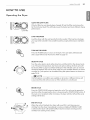
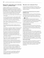
Rotate the cycle selector knob to select the desired dry cycle. Add cycle options or adjust settings with the touch
of a button.
The wide-opening door provides easy access for loading and unloading. The door hinge can be reversed to adjust
for installation location.
The ultra-large stainless steel drum offers superior durability, The drum is equipped with a yellow light that
illuminates when the dryer door is open and turns off when the door is closed,
LG's steam technology allows you to inject fabrics with a swirling jet of hot steam to refresh clothes, reduce static,
and make ironing easier. Simply select the STEAM FRESW Mcycle, or you can add a Steam option to selected cycles.
The FLOW SENSETM duct blockage sensing system detects and alerts you to restrictions in the installed household
ductwork that reduce exhaust airflow through the dryer. If you see the alert: Clean or repair the ducts to remove
the restrictions. Keep your ducts clean to help increase efficiency and reduce long drying times caused by blocked
ducts.
Should you experience any technical difficulty with your dryer, it has the capability of transmitting data via your
telephone to the Customer Information Center. The call center agent records the data transmitted from your
machine and uses it to analyze the issue, providing a fast and effective diagnosis.
@
Protocol P154
Sanitization Performance of
Residential Clothes dryer

INTRODUCINGYOURDRYER9
INTRODUCING YOUR DRYER
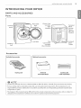
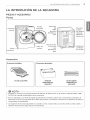
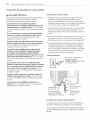
PARTS AND ACCESSORIES
Parts
Control'
panel
Leveling__
feet
Reversible
door
\
Lint filter
Power Cord
Location
(Gas
Models)
Gas
Connection
Location
(Gas Models)
Terminal
Block
Access
Panel
(Electric
Models)
Exhaust
Duct
Outlet
Accessories
Drying rack Pedestal Stacking kit
(sold separately) (sold separately)
@ NOTE --_
Contact LG Customer Service at 1-800-243-0000 (1-888-542-2623 in Canada) if any accessories are missing,
For your safety and for extended product life, use only authorized components, The manufacturer is not
responsible for product malfunction or accidents caused by the use of separately purchased unauthorized
components or parts,
The images in this manual may be different from the actual components and accessories, and are subject to
change by the manufacturer without prior notice for product improvement purposes, ./

"10 INTRODUCING YOUR DRYER
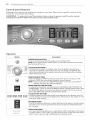
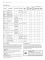
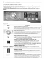
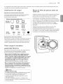
Control panel features
Following are instructions for starting and using your new dryer. Please refer to specific sections of this
manual for more detailed information.
_WARNING : To reduce the risk of fire, electric shock, or injury to persons, read this entire manual,
including the Important Safety Instructions, before operating this dryer.
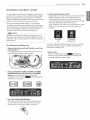
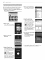
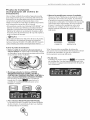
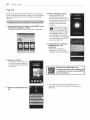
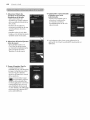
Operation
Button I Description
i- Press to turn the dryer ON. Press again to turn the dryer OFF.
iNOTE : Pressing the ON/OFF button during a cycle will cancel that cycle and any
. iload settings will be lost.
J
B_,,_,...... _°_'_iCYCLE SELECTOR KNOB
......_o°, '_'_;_; i- Turn this knob to select the desired cycle. Once the desired cycle has been
........._ ...._ i selected, the standard presets will be shown in the display. On MANUAL DRY
.............J/ _,_,vi cycles, these settings can be adjusted using the cycle setting buttons anytime
............. °°_'°°_°_'°'ibefore starting the cycle.
,
iSTART/PAUSE BUTTON
i- Press this button to STARTthe selected cycle. If the dryer is running, use this
button to PAUSE the cycle without losing the current settings.
iNOTE : If you do not press the START/PAUSE button to resume a cycle within 4
minutes, the dryer turns off automatically.
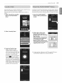
iMORE TIME/LESS TiME BUTTONS
i- To adjust the drying time, use these buttons with MANUAL DRY,TIME DRY, and
i STEAM FRESHTM cycles, as well as the REDUCE STATICand EASY IRON options. Press
i the MORE TIME button to increase the selected manual cycle time by a minute;
i press LESSTIME to decrease the cycle time by a minute.
i- Use these buttons to select the desired cycle settings for the selected cycle. The
current settings are shown in the display. Press the button for that option to view
and select other settings.
OPTION BUTTONS
-The OPTION buttons allow you to select additional cycle options. Certain buttons
also allow you to activate special functions by pressing and holding the button
for 3 seconds.
iSTEAM FUNCTIONS
st ._ ;;,_t_v' - LG's steam technology allows you to inject fabrics with a swirling jet of hot steam
t_ _ _ _l_ to refresh clothes, reduce static, and make ironing easier. Simply select the steam
fresh TM cycle, or you can add a STEAM option to selected cycles.

INTRODUCINGYOURDRYER11
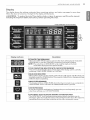
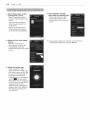
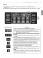
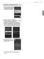
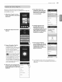
Display
The display shows the settings, estimated time remaining, options, and status messages for your dryer.
When the dryer is turned on, the light in the display will illuminate.
_WARNING : To reduce the risk of fire, electric shock, or injury to persons, read this entire manual,
including the Important Safety Instructions, before operating this dryer.
-kPress & H01d3sec. for Extra Functions
iESTIMATED TIME REMAINING
- When the START/PAUSE button is pressed, the dryer will display the estimated
i (SENSOR DRY) or set time (TIME DRY) remaining, and begin tumbling.
iNOTE ;The cycle time on SENSOR DRYcycles may fluctuate as the dryer
, , recalculates drying time for optimal results ,
iCYCLE COMPLETION INDICATOR WITH CHECK FILTER REMINDER
j-This portion of tile display shows which stage of the drying cycle is currently
i underway (CHECK FILTER,DRYING, or COOLING).
iCHilD L6(:K iNDICAT6R
i- When CHILD LOCK is set, the CHILD LOCK indicator will appear and all buttons are
i disabled except the POWER button. This prevents children from changing settings
i while the dryer is operating
iCHECK FILTER REMINDER
[- The display will show CHECK FILTERwhen tile dryer is turned on as a reminder to
i check the filter. It turns off when the START/PAUSE button is pressed.
' i
iCUSTOM PROGRAM
i- If you have a special combination of settings that you use frequently, you can
i save these settings as a CUSTOM PROGRAM.
i
iFLOW SENSE"_ DUCT BLOCKAGE SENSING SYSTEM INDICATOR
i- The FLOW SENSETMduct blockage sensing system detects and alerts you to
i blockages in the cluctwork that reduce exhaust flow from the dryer. This improves i
operating efficiency and helps minimize service calls, saving your money.
J
I

12 INSTA LLAiTION INSTRUCTIONS
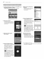
INSTALLATION INSTRUCTIONS
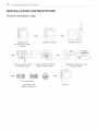
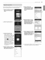
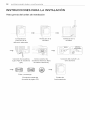
Preview installation order
Checking and
choosing the proper
location
Leveling the dryer Venting the Dryer
Connecting Gas Dryers Connecting Electric Dryers
(Gas Dryer Type) (Electric Dryer Type)
Plugging in the power cord
and grounding
Press and hold
installation test
(Refer to page 29.)
Test run

INSTALLAiTION INSTRUCTIONS ]3
Insfallafion Iocafion requiremenfs
_WARNING
Read all installation instructions completely before installing and operating your dryer! It is important that
you review this entire manual before installing and using your dryer. Detailed instructions concerning electrical
connections, gas connections, and exhaust requirements are provided on the following pages.
• A location that allows for proper exhaust installation.
A gas dryer must be exhausted to the outdoors. See
Venting the dryer.
• A grounded electrical outlet located within 2 ft.
(61 cm) of either side of the dryer. See Connecting
electric dryers,
. A sturdy floor to support the total dryer weight of 200
Ibs (90.7 kg).The combined weight of a companion
appliance should also be considered.
. No other fuel-burning appliance can be installed in the
same closet as a dryer.
Do not operate your dryer at temperatures below 45°F (7°C). At lower temperatures, the dryer might not shut off
at the end of an automatic cycle. This can result in longer drying times. The dryer must not be installed or stored in
an area where it will be exposed to water and/or weather. Check code requirements. Some codes limit, or do not
permit, installation of the dryer in garages, closets, mobile homes or sleeping quarters. Contact your local building
inspector.
[ii NOTE
level floor with a maximum slope of 1 inch (2,5 cm) under entire dryer. Clothes may not tumble properly, and
utomatic sensor cycles may not operate correctly if dryer is not level.
or a garage installation, you will need to place the dryer at least 18 inches (46 cm) above the floor. If using a
pedestal, you will need 18 inches (46 cm) to the bottom of the dryer.
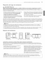
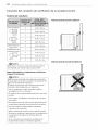
Clearances
3"
24in,_ _ 3"
_ (155cm2) ,6cm)
Ir'*l_30"_ls"-I _ _"_11_ 27"_-I1_ " _"*11_3o"_-Is"**l
{2,5cm) (76,1cm){12,Tcm) {2,5cm) {68,6cm) {2,5cm) {2,5cm) {76,1cm) {12,7cm)
iNSTALLATION SPACING FOR RECESSEDAREA OR CLOSET iNSTALLATiON
The following spacing dimensions are recommended for this dryer. Although this dryer has been tested for spacing
of 1inch (2.5cm) clearance on the sides and rear, the recommended spacing should be considered for the following
reasons:
• Additional spacing should be considered for ease of
installation and servicing.
• Additional clearances might be required for wall, door
and floor moldings.
. Additional spacing should be considered on all sides
of the dryer to reduce noise transfer.
For closet installation, with a door, minimum
ventilation openings in the top and bottom of the
door are required. Louvered doors with equivalent
ventilation openings are acceptable.
. Companion appliance spacing should also be
considered.
Iia NOTE
here should be at least a little space around the dryer (or any other appliance) to eliminate the transfer of
ibration from one to the other, With enough vibration, the appliances will make noise or touch each other
using paint damage and making even more noise,

14 INSTALLATION INSTRUCTIONS
InsfMlafion with optional pedesfM base or stacking kit
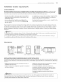
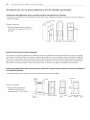
RECOMMENDED INSTALLATION SPACING FOR CABINET INSTALLATION
• For cabinet installation with a door, minimum ventilation openings in tile top of the cabinet are required.
*Required spacing
**For side or bottom venting,
2 inches (5.I cm) spacing is allowed.
7"*(17.8cm) 7"_(17.8cm)
s'2 30" _"'
m
(22.g cm)
_l J_ _iI_
27" 1"
(12.7cm) (76.1cm) (2.5cm) (2.5 cm)(68.6 cm)(2.5 cm)
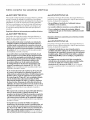
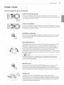
CLOSET VENTILATION REQUIREMENTS
Closets with doors must have both an upper and lower vent to prevent heat and moisture buildup in the closet, One
upper vent opening with a minimum opening of 48 sq, in, (310 cm2)must be installed no lower than 6 feet above the
floor, One lower vent opening with a minimum opening of 24 sq, in. (155 cm 2)must be installed no more than one
foot above the floor. One example shown uses vent grilles in the door,
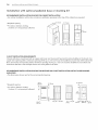
RECOMMENDED INSTALLATION SPACING FOR RECESSED OR CLOSET INSTALLA TION, WITH STACKED WASHER
AND DRYER
• The dimensions shown are for the recommended spacing.
*Required spacing
**For side or bottom venting,
2 inches (5.I cm) spacing is allowed.
46 in.2 *
(310 crn2) 3_ (7.6 crn)
Z
7.6 cm
24 in.2*
(155 crn2)
6"*(15.2cm)
f
_1"*(2.5crn) 51/2,**_ =- _ 1" :_- _27,_ 41,,
(14 crn) (2.5 crn) 68.6 crn (2.5 crn)

INSTALLAiTION INSTRUCTIONS 15
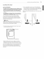
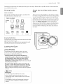
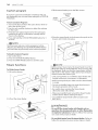
Leveling fhe dryer
_WARNING
• To reduce the risk of injury to persons, adhere to all
industry recommended safety procedures including
the use of long sleeved gloves and safety glasses.
Failure to follow this warning can cause serious injury
or death.
• The appliances are heavy. Two or more people are
required when instaffing the dryer. Failure to follow
this warning can cause serious injury or death.
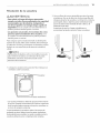
To ensure that the dryer provides optima] drying
performance, it must be level. To minimize vibration,
noise, and unwanted movement, the floor must be a
perfectly level, solid surface.
-@NOTE -_
Adjust the leveling feet only as far as necessary to
level the dryer. Extending the leveling feet more than
1.Position the dryer in the final location. Place a level
across the top of the dryer.
e _Level
.eveling Feet
• All four leveling feet must rest solidly on the floor.
Gently push on the top corners of the dryer to make
sure that the dryer does not rock from corner to corner.
If you are installing the dryer on the optional pedestal,
you must use the leveling feet on the pedestal to
level the dryer. The dryer leveling feet should be fully
retracted.
2. Use an adjustable wrench to turn the leveling feet.
Turn clockwise to raise the dryer or counterclockwise
to lower it. Raise or lower the leveling feet until dryer
is level from side to side and front to back.
Make sure that all 4 leveling feet are in firm contact with
the floor.

"16 INSTALLATIONINSTRUCTIONS
Reversing the door
AWARNING ..............................................................................,
•To avoid damage to the dryer or the door, support
the door with a stool or box that fits under the
door, or have an assistant support the weight of
the door.
• Always reverse the door BEFORE stacking the
dryer on top of the washer.
• Avoid dropping the door to avoid damage to the
door or the floor.
THE DRYERDOOR ISVERY LARGE AND HEAVY.Failure
to follow the instructions below can result in damage
to the dryer, property damage or injury to persons,
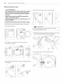
1,Open the dryer door,
Open Door I
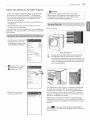
2, You will be removing the screws shown below
(6 on left, 4 on right).
4. Remove the two latch screws and the latch,
/J ....
Latch SCF?' _i_
// / .....
\
IiI@CAUTION
e sure to support the weight of the door before )
moving the hinge screws.
S. Hold the hinge in place while removing the four hinge
screws (to prevent the door from dropping).
eScrew
3. Remove the four decorative screws on the left using a
screwdriver.
6. Remove the door from the cabinet cover.
/
/ /
/ J
/
Decorative
Hinge
Screw

INSTALLATIONINSTRUCTIONS17
Reversing the door (cont.)
AWARNING .............................................................................._,
•To avoid damage to the dryer or the door, support
the door with a stool or box that fits under the
door, or have an assistant support the weight of
the door.
• Always reverse the door BEFORE stacking the
dryer on top of the washer.
• Avoid dropping the door to avoid damage to the
door or the floor.
THE DRYERDOOR ISVERY LARGE AND HEAVY.Failure
to follow the instructions below can result in damage
to the dryer, property damage or injury to persons,
1.Move the door to the left side and line up the holes in
the hinge with the holes in the cabinet.
:_i _ //
Hinge hole
S@ CAUTION %
IBe sure to support the weight of the door before
/
2, Hold the hinge in place while inserting the two hinge
screws (to prevent the door from dropping).
/;
A
/
i
4. Insert the four decorative screws on the right side.
Screw
/
S. Check that the door closes and latches properly.
"Swing Door
!
11 z.=] : >i .......
3. Insert the latch on the right side and install the latch
screws,
I Screw

18 INSTALLAiTIONINSTRUCTIONS
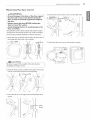
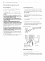
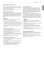
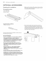
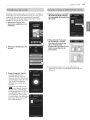
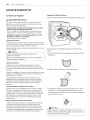
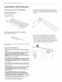
Insfalling fhe Side Venf Kif
_WARNING
• Use a heavy metal vent.
• Do not use plastic or thin foil duct.
• Clean old ducts before instalEng this dryer.
• To reduce the risk of injury to persons, adhere to all
industry recommended safety procedures including
the use of long sleeved gloves and safety glasses.
• Failure to follow all of the safety warnings in this
manual could result in property damage, injury to
persons, or death.
Your new dryer is shipped to vent to the rear.
It can also be configured to vent to the bottom or side
(right-side venting is not available on gas models).
An adapter kit, part number 383EEL9001B, may be
purchased from your LG retailer, This kit contains the
necessary duct components to change the dryer vent
location,
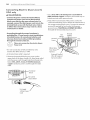
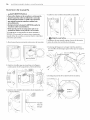
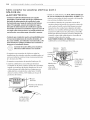
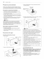
1.Remove the rear exhaust duct retaining screw. Pull
out the exhaust duct.
Retaining
Screw
Exhaust Duct
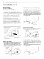
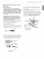
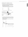
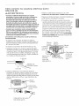
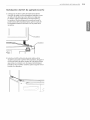
3.Preassemble a 4-inch (10.2 cm) elbow to the next
4-inch (10,2 cm) duct section, and secure all joints
with duct tape. Be sure that the male end of the elbow
faces AWAY from the dryer. Insert the elbow/duct
assembly through the side opening and press it onto
the adapter duct. Secure in place with duct tape.
Be sure that the male end of the duct protrudes 1_/2
inches (3.8 cm) to connect the remaining ductwork,
Attach the cover plate to the back of the dryer with
the included screw.
Cover
Plate
I
] 2/4,,
.(3.8 cm)
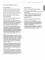
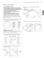
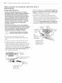
OPTION 2: BOTTOM VENTING
2. Press the adapter duct onto the blower housing and
secure it to the base of the dryer as shown.
Adapter
Bracket
OPTION I: SIDE VENTING
2, Press the tabs on the knockout and carefully remove
the knockout for the desired vent opening (right-
side venting is not available on gas models). Press the
adapter duct onto the blower housing and secure to
the base of the dryer as shown.
Bracket
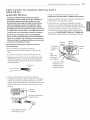
3.Insert the 4-inch (10,2 cm) elbow through the rear
opening and press it onto the adapter duct. Be sure
that the male end of the elbow faces down through
the hole in the bottom of the dryer. Secure it in place
with duct tape.
Attach the cover plate to the back of the dryer with
the included screw.
Cover,
Plate

INSTALLAiTIONINSTRUCTIONS"]_
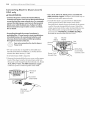
Venting the Dryer
_WARNING
To reduce the risk of fire, electric shock, or injury to persons when using this appliance, follow basic precautions,
including the following:
• Do not crush or collapse ductwork. Failure to follow
these instructions can result in fire or death,
• Do not allow ductwork to rest on or contact sharp
objects, Failure to follow these instructions can result
in fire or death,
• If connecting to existing ductwork, make sure it
is suitable and clean before installing the dryer.
Failure to follow these instructions can result in fire or
death,
• Venting must conform to local building codes.
Failure to follow these instructions can result in fire or
death,
• Gas dryers MUST exhaust to the outdoors,
Failure to follow these instructions can result in fire or
death,
• Use only 4-inch (10.2 cm) rigid or flexible metal
ductwork inside the dryer cabinet and for venting
outside. Failure to follow these instructions can result
in fire or death,
• To reduce the risk of fire, combustion, or
accumulation of combustible gases, DO NOT
exhaust dryer air into an enclosed and unventilated
area, such as an attic, wall, ceiling, crawl space,
chimney, gas vent, or concealed space of a
building. Failure to follow these instructions can result
in fire or death,
• To reduce the risk of fire, DO NOT exhaust the dryer
with plastic or thin foil ducting.
Failure to follow these instructions can result in fire or
death,
• The exhaust duct must be 4 inches (10.2 cm) in
diameter with no obstructions. The exhaust duct
should be kept as short as possibleo Make sure
to clean any old ducts before installing your new
dryer. Failure to follow these instructions can result in
fire or death,
. Rigid or semirigid metal ducting is recommended
for use between the dryer and the wall. In special
installations when it is impossible to make a
connection with the above recommendations, a
UL-listed flexible metal transition duct may be used
between the dryer and wall connection only. The
use of this ducting will affect drying time. Failure to
follow these instructions can result in fire or death,
. DO NOT use sheet metal screws or other fasteners
which extend into the duct that could catch lint and
reduce the efficiency of the exhaust system. Secure
all joints with duct tape. Failure to follow these
instructions can result in fire or death.
. To maximize operating results, please observe the
duct length limitations noted in the chart on the
next page. Failure to follow these instructions can
result in fire or death.
. Ductwork isnot provided with the dryer. You
should obtain the necessary ductwork Iocaffy. The
end cap should have hinged dampers to prevent
backdraft when the dryer isnot in use. Failure to
follow these instructions can result in fire or death.
. The total length of flexible metal duct shall not
exceed 8 ft. (2.4 m)
. In Canada, only those foil-type flexible ducts,
if any, specifically identified for use with the
appliance by the manufacturer shall be used. In the
United States, only those foil-type flexible ducts, if any,
specifically identified for use with the appliance by the
manufacturer and that comply with the Outline for
Clothes Dryer Transition Duct, Subject 21S8A, shall be
used.

20 INSTALLATIONINSTRUCTIONS
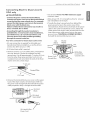
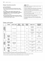
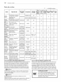
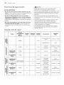
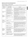
Venting the Dryer (cont.)
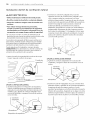
Ductwork
Recommended
(10.2 cm)
(10.2 cm)
Use only for
short run
installations
J
o
I
2
3
4
o
I
2
3
4
65 ft, (1g,8 m)
55 ft. (16.8 m)
47 ft. (14.3 m)
36 ft. (11,0 m)
28 ft. (8.5 m)
55 ft. (16.8 m)
47 ft. (14.3 m)
41 ft. (12.5 m)
30 ft. (9.1 m)
22 ft, (6,7 m)
-@NOTE 1
Deduct 6 ft.(I.8m) foreach additionalelbow. Use of
more than four90* elbows isnot recommended.
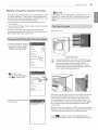
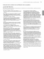
ROUTING AND CONNECTING DUCTWORK
- @ NOTE
Followthe guidelinesbelow tomaximize drying
performance and reduce lintbuildupand
condensationinthe ductwork,
Ductwork and fittingsare NOT includedand must be
purchased separately,
.Use 4-inch(10.2cm) diameter rigidorsemirigid
metalductwork,
.The exhaustduct run should be asshortas possible,
.Use as few elbow joints as possible,
.The male end of each section of exhaust duct must
point away from the dryer,
. Use duct tape on all duct joints,
. Insulate ductwork that runs through unheated areas
in order to reduce condensation and lint buildup on
duct surfaces.
• Failure to exhaust the dryer correctly will void the
CORRECT VENTING
INCORRECT VENTING
Page is loading ...
Page is loading ...
Page is loading ...
Page is loading ...
Page is loading ...
Page is loading ...
Page is loading ...
Page is loading ...
Page is loading ...
Page is loading ...
Page is loading ...
Page is loading ...
Page is loading ...
Page is loading ...
Page is loading ...
Page is loading ...
Page is loading ...
Page is loading ...
Page is loading ...
Page is loading ...
Page is loading ...
Page is loading ...
Page is loading ...
Page is loading ...
Page is loading ...
Page is loading ...
Page is loading ...
Page is loading ...
Page is loading ...
Page is loading ...
Page is loading ...
Page is loading ...
Page is loading ...
Page is loading ...
Page is loading ...
Page is loading ...
Page is loading ...
Page is loading ...
Page is loading ...
Page is loading ...
Page is loading ...
Page is loading ...
Page is loading ...
Page is loading ...
Page is loading ...
Page is loading ...
Page is loading ...
Page is loading ...
Page is loading ...
Page is loading ...
Page is loading ...
Page is loading ...
Page is loading ...
Page is loading ...
Page is loading ...
Page is loading ...
Page is loading ...
Page is loading ...
Page is loading ...
Page is loading ...
Page is loading ...
Page is loading ...
Page is loading ...
Page is loading ...
Page is loading ...
Page is loading ...
Page is loading ...
Page is loading ...
Page is loading ...
Page is loading ...
Page is loading ...
Page is loading ...
Page is loading ...
Page is loading ...
Page is loading ...
Page is loading ...
Page is loading ...
Page is loading ...
Page is loading ...
Page is loading ...
Page is loading ...
Page is loading ...
Page is loading ...
Page is loading ...
Page is loading ...
Page is loading ...
Page is loading ...
Page is loading ...
Page is loading ...
Page is loading ...
Page is loading ...
Page is loading ...
Page is loading ...
Page is loading ...
Page is loading ...
Page is loading ...
-
 1
1
-
 2
2
-
 3
3
-
 4
4
-
 5
5
-
 6
6
-
 7
7
-
 8
8
-
 9
9
-
 10
10
-
 11
11
-
 12
12
-
 13
13
-
 14
14
-
 15
15
-
 16
16
-
 17
17
-
 18
18
-
 19
19
-
 20
20
-
 21
21
-
 22
22
-
 23
23
-
 24
24
-
 25
25
-
 26
26
-
 27
27
-
 28
28
-
 29
29
-
 30
30
-
 31
31
-
 32
32
-
 33
33
-
 34
34
-
 35
35
-
 36
36
-
 37
37
-
 38
38
-
 39
39
-
 40
40
-
 41
41
-
 42
42
-
 43
43
-
 44
44
-
 45
45
-
 46
46
-
 47
47
-
 48
48
-
 49
49
-
 50
50
-
 51
51
-
 52
52
-
 53
53
-
 54
54
-
 55
55
-
 56
56
-
 57
57
-
 58
58
-
 59
59
-
 60
60
-
 61
61
-
 62
62
-
 63
63
-
 64
64
-
 65
65
-
 66
66
-
 67
67
-
 68
68
-
 69
69
-
 70
70
-
 71
71
-
 72
72
-
 73
73
-
 74
74
-
 75
75
-
 76
76
-
 77
77
-
 78
78
-
 79
79
-
 80
80
-
 81
81
-
 82
82
-
 83
83
-
 84
84
-
 85
85
-
 86
86
-
 87
87
-
 88
88
-
 89
89
-
 90
90
-
 91
91
-
 92
92
-
 93
93
-
 94
94
-
 95
95
-
 96
96
-
 97
97
-
 98
98
-
 99
99
-
 100
100
-
 101
101
-
 102
102
-
 103
103
-
 104
104
-
 105
105
-
 106
106
-
 107
107
-
 108
108
-
 109
109
-
 110
110
-
 111
111
-
 112
112
-
 113
113
-
 114
114
-
 115
115
-
 116
116


LG DLGX4271W Owner's manual
- Category
- Electric laundry dryers
- Type
- Owner's manual
- This manual is also suitable for
Ask a question and I''ll find the answer in the document
Finding information in a document is now easier with AI
in other languages
Related papers
Other documents
-
Haier GDZ5-1 User manual
-
GE DSXH47 User manual
-
LG Electronics DLGX7801WE User manual
-
Maytag MDG17CSAWW - 7.4 cu. Ft. Commercial Gas Dryer Installation Instructions Manual
-
 Kenmore Elite 79671422410 Owner's manual
-
-
-
-
Samsung DV316BGC/XAA Owner's manual
-
