Frigidaire FEB786CEBA Installation guide

Category
Microwaves
Type
Installation guide
INSTALLATION AND SERVICE MUST BE PERFORMED BY A QUALIFIED INSTALLER.
IMPORTANT: SAVE FOR LOCAL ELECTRICAL INSPECTOR'S USE.
READ AND SAVE THESE INSTRUCTIONS FOR FUTURE REFERENCE.
FOR YOUR SAFETY: Do not store or use gasoline or other flammable vapors and liquids in
the vicinity of this or any other appliance.
Your new wall oven has been designed to fit a limited variety of cutout sizes to make the job of installing
easier. The first step of your installation should be to measure your current cutout dimensions and
compare them to the cutout dimensions chart below for your model. You may find little or no cabinet
work will be necessary.
Do not remove spacers (if equipped) on the side walls and/or on the back of the built-in oven.
These spacers center the oven in the space provided. The oven must be centered to prevent excess heat buildup
that may result in heat damage or fire.
r .... , * Suggested distance from floor is 31 " (78.7 cm)
openings "'_,_l ..... |27" Min.
MJmmum required distance Js4 1/2" (11.4 cm) (68.6 ___
Cutout
_ for self-clean models.
Minimum required distance is 10" (25.4 cm)
................ for easy-clean models. 1 1/2"[_'_
_:_ (3 8 cm) I
Do not install the oven ........ t" 28 3/32" / I
:...... / 71.4 cm) H I
closer than the
Door / II
I dimension "K" (see EOpen / ....
table) toanyadjoiningcabinetryor _ re _ _
walls on the door hinge side. This will
interfere with oven rackremovakFigure2 i: : i':i'" ! (7___
NOTE:
- Self-clean Models: Allow at least 27 ¼" (
clearance for door depth when it is open.
- Easy-clean Models: Allow at least 26 ¼" (66.7 cm)
clearance for door depth when it is open. 2" (5 cm) Wide Wood
Spacer if Needed
NOTE: For a cutout height greater than 29" (73.6 cm) add
one 2" (5 cm) wide wood spacer to each side of the opening
under the appliance side rails.
Electrical Junction box
location and Hole for
Cable space 2"(5.1 cm)
from left wall for Self-
Clean Models.
/
Electrical junction box
/
"" --_,/ and Hole for Cable
G_-/'=I space 2" (5.1 cm)
_i from right wall for
Easy Clean Models.
" "; _3"(7.6 cm)
.-. Max.
Electrical junction box
2" (5.1 cm)
Min. (right or left side
depending of model)
NOTE: Base must be capable of supporting 150 pounds (68 Kg).
Figure 1
27" (68.6 cm) EasyClean
27" (68.6 cm) Self Clean
26 7/8 (68.2)
26 7/8 (68.2)
30 9/16 (77.6)
31 1/8 (79.1)
24 11/16 (62.7)
24 11/16 (62.7)
24 1/4 (61.6)
25 3/8 (64.5)
27" (68.6 cm) EasyClean 24 7/8 (63.2) 25 5/32 (63.91 23 1/2 (59.7) 28 1/8 (71.4) 29 5/8 (75.2) 3 (7.6)
27" (68.6 cm) SelfClean 247/8(63.2) 25 1/4(64.1) 23 1/2(59.7) 28 1/8(71.4) 30 1/8(76.5) 41/2(11.4)
All dimensions are in inches (cm).
Some models are not available in Canada. P/N 318201508 (0201) Rev.
English - pages 1-9
1 Espa_ol - pctginas 10-18
Fran_ais - pages 19-27
Important Notes to the Installer
1. Read all instructions contained in these installation
instructions before installing the wall oven.
2. Remove all packing material from the oven
compartments before connecting the electrical supply to
the wall oven.
3. Observe all governing codes and ordinances.
4. Besure to leavethese instructions with the consumer.
5. THESEOVENS ARE NOT APPROVED FORSTACKABLE
OR SIDE-BY-SIDE INSTALLATION.
Important Note to the Consumer
Keep these instructions with your owner's guide for future
reference.
IMPORTANT SAFETY
INSTRUCTIONS
Be sure your wall oven is installed and grounded
properly by a qualified installer or service
technician.
This wall oven must be electrically grounded in
accordance with local codes, in their absence,
with the National Electrical Code ANSI/NFPA No.70
- latest edition in the United States, or with CSA
Standard C22.1, Canadian Electrical Code, Part 1, in
Canada
Stepping, leaning or sitting on the
door of this wall oven can result in serious injuries
and can also cause damage to the wall oven.
Never use your wall oven for warming or heating
the room. Prolonged use of the wall oven without
adequate ventilation can be dangerous.
grounded branch circuit, protected by a circuit breaker or
fuse, having amperage as noted on the rating plate (the
rating plate is located on the oven frame).
Observe all governing codes and local ordinances
1. A 3-wire or 4-wire single phase 120/240 or 120/208
Volt, 60 Hz AC only electrical supply is required on
a separate circuit fused on both sides of the line
(time-delay fuse or circuit breaker is recommended).
DO NOT fuse neutral. The fuse size must not exceed
the circuit rating of the appliance specified on the
nameplate. Consideration must be given for a
combination built-in oven and cooktop refer to unit
serial plate of each.
NOTE: Wire sizes and connections must conform with
the fuse size and rating of the appliance in accordance
with the American National Electrical Code ANSI/NFPA
No. 70-latest edition, or with Canadian CSA Standard
C22.1, Canadian Electrical Code, Part 1, and local codes
and ordinances.
An extension cord should not be used
with this appliance. Such use may result in a fire,
electrical shock, or other personal injury.
2. The appliance should be connected to the fused
disconnect (or circuit breaker) box through flexible
armored or nonmetallic sheathed cable. The flexible
armored cable extending from the appliance should
be connected directly to the junction box. The
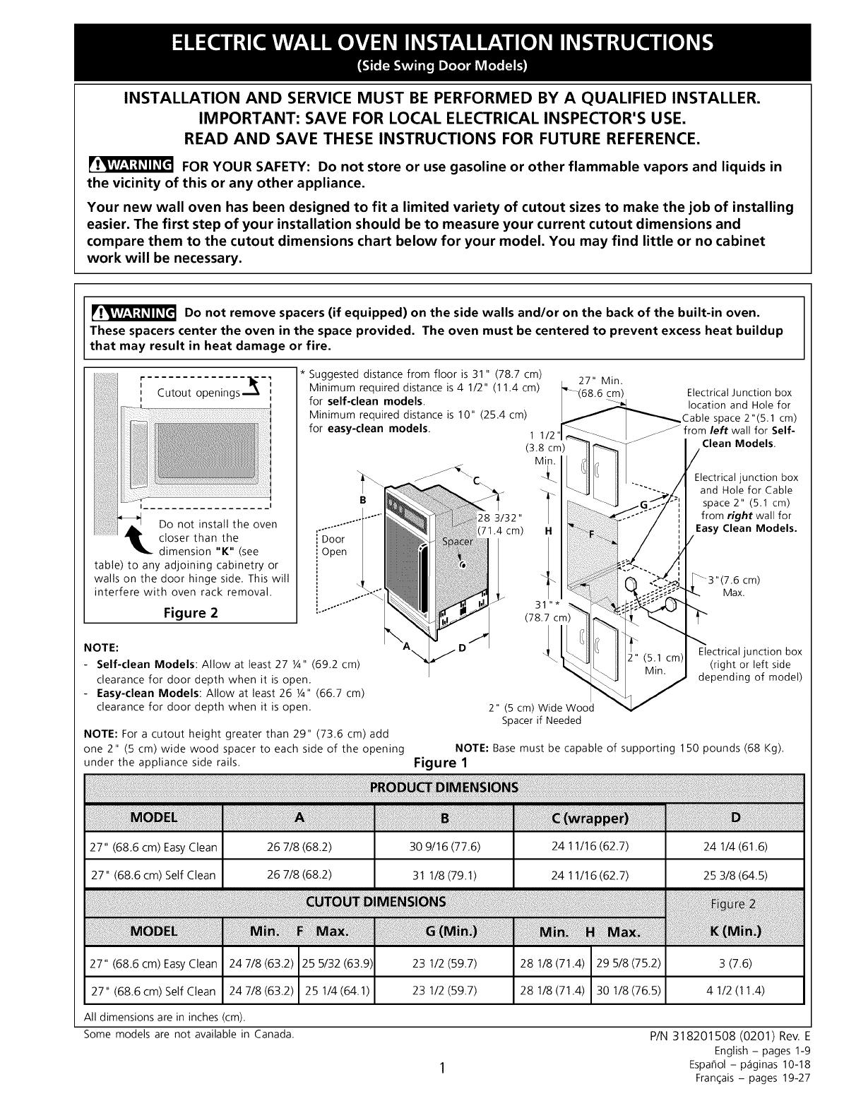
junction box should be located as shown in figure 1
with as much slack as possible remaining in the
cable between the box and the appliance, so it can
be moved if servicing is ever necessary.
3. A suitable strain relief must be provided to attach
the flexible armored cable to the junction box.
The electrical power to the oven must
be shut off while line connections are being made.
Failure to do so could result in serious injury or
death.
1.Carpentry
Refer to figure 1 and 2 for the dimensions applicable to
your appliance, and the space necessary to receive the
oven. The oven support surface may be solid plywood or
similar material, however the surface must be level from
side to side and from front to rear. Leave the bottom of
the cabinet partially opened to permit free air
circulation, otherwise water condensation may appear
inside the control panel when operating the oven.
2. Electrical Requirements
This appliance must be supplied with the proper voltage
and frequency, and connected to an individual, properly
2
Electrical Shock Hazard
Electrical ground is required on this appliance.
Do not connect to the electrical supply until
appliance is permanently grounded.
Disconnect power to the junction box before
making the electrical connection.
This appliance must be connected to a
grounded, metallic, permanent wiring system,
or a grounding connector should be connected
to the grounding terminal or wire lead on the
appliance.
Do not use the gas supply line for grounding
the appliance.
Failure to do any of the above could result in a
fire, personal injury or electrical shock.
Wait at least three (3) hours after
receiving this built-in oven before switching the power on
to prevent possible damage to the built-in oven control
at power on.
3. Adjusting Oven Height
Oven height can be adjusted when needed to fit into an
existing cabinet cutout opening. To adjust oven height:
1. Laythe oven on its back.
2. Remove the 5 or 6 screws fastening the side of each
extension angle (see Figure 3) to the bottom side of
the oven.
3. Remove the 3 screws (Self-clean models only)
fastening each extension angle to the underside of
the oven. Remove the extension angles.
4. Replace the 6 screws (Self-clean models only) in
their original locations underneath the oven.
5. Move the extension angles to their new positions to
fit the existing cutout opening. Available holes are
spaced 1/2" (1.3 cm) apart for a possible adjustment
of 1 1/2" (3.8 cm) maximum.
6. Line up the appropriate holes in the extension panels
and sides of the oven. Replace the 5 or 6 screws
fastening each of the extension angles to the side
wall of the unit. Return oven to upright position.
5 or 6 Screw
j_ Fasteners
7
/
Self-Clean
Model (0nly):_
3 Screw
Fasteners Under
Extension Angle
1 I/2"
(3,8 cm)
jfi
_".... WALL
NOTE: Right-Hand Shown........... OVEN
Left-Hand is Opposite
Figure 3 - EXTENSION ANGLE (SIDE VIEW)
4. Electrical connection
It is the responsibility and obligation of the consumer to
contact a qualified installer to assure that the electrical
installation is adequate and is in conformance with the
National Electrical Code ANSI/NFPA No. 70qatest
edition, or with CSA Standard C22.1, Canadian
Electrical Code, Part 1, and local codes and ordinances.
Electrical ground is required on this appliance.
These appliances are equipped with a copper conductor
flexible cable. If connection is made to aluminum house
wiring, use only special connectors which are approved
for joining copper and aluminum wires in accordance
with National Electrical Code and local codes and
ordinances.
These appliances are manufactured with a (white)
neutral power supply wire and a frame connected green
(or bare copper) grounding wire.
.
If local codes permit connection of the frame
grounding conductor to the neutral (white)
wire: (The 3-conductor cord or cable must be
replaced with a 4-conductor cord or cable where
grounding through the neutral conductor is
prohibited in new installations, mobile homes,
recreational vehicles or in other areas where local
codes do not permit neutral grounding)
Connect the green (or bare copper) wire and white
wire from the appliance cable to the supply cable
ground wire (white or bare) inside the junction box.
Connect the remaining wires inside the junction box
from the power supply cable to the matching colors
of the appliance cable wires (see Figure 4).
Cable from Power Supply
Cable from appliance
Figure 4
3-WIRE GROUNDED JUNCTION BOX
Improper connection of aluminum
house wiring to copper leads can result in a short
circuit or fire. Use only connectors designed for
joining copper to aluminum, and follow the
manufacturer's recommended procedure closely.
3
, If used in mobile homes or if local codes DO
NOT permit connection of the frame grounding
conductor to the neutral (white) wire, separate
the white and bare copper ground wires that extend
out of the end of the supply cable of the appliance.
Connect the white wire from supply cable to the
neutral white wire in the junction box. Connect the
black and red wires from the supply cable to the
matching color wires in the junction box. The bare
wire must now be used to ground the appliance in
accordance with local electrical codes. Connect the
bare copper ground wire to the grounded lead in the
service panel. DO NOT ground to a gas supply pipe.
DO NOT connect to electrical power supply until
appliance is permanently grounded. Connect the
ground wire before turning on the power
(see Figure 5).
Cable from Power Supply
U.L.-Listed Conduit
Connector (or CSA listed)
Cable from appliance
Figure 5
4-WIRE GROUNDED JUNCTION BOX
[Irl_';!_lT/=_J_l If connecting to a 4-wire electrical
system (mobile homes), the appliance frame MUST
NOT be connected to the neutral wire of the 4-wire
electrical system.
NOTE TO ELECTRICIAN: The armored cable leads
supplied with the appliance are CSA-recognized for
connection to larger gauge household wiring. The
insulation of the leads is rated at temperatures much
higher than temperature rating of household wiring. The
current carrying capacity of the conductor is governed by
the temperature rating of the insulation around the wire,
rather than the wire gauge alone.
Do not lift the oven by the door
handle.
5. Preparing the Wall Oven
A. Easy Clean Models
This wall oven can easily be modified to a left or a
right hand door opening. It is preferable to reverse
door opening prior to the installation of the wall oven
into the cabinet cavity. If wall oven is already installed,
removed the 4 lateral screws securing it against the
cabinet, then pull wall oven outward by approx. 2" (5
cm).
Two of the lateral screws are located at the low end of
upper trim; the other 2 are used to hold the lower trim
in place.
i
Figure 6
Door Reversal Procedure (see Figure 6)
1. Pull the door open.
2. While supporting the door with one hand, remove
the 2 screws securing top hinge #1 to the door.
Remove the top hinge, then lift up the door such
as to clear the lower hinge pin and remove the
door.
3. Lay the door on a table protected by a blanket;
the inner door surface must face toward you.
4. Remove the 2 screws which secure the handle;
remove the handle. Remove filler plate #2, #3,
and #12 using a flat blade tool.
5. Reassemble upper hinge #1 at the lower end and
on the opposite side of the door.
6. Remove lower hinge #4. Relocate the nylon
washer on the lower hinge pin.
7. Remove screws securing the top and bottom door
trims #5 and #6 to the door; remove these trims.
8. Slide the glass panel flush with the edge of the
enamelled steel inner door (toward the new
handle location).
9. Invert position of trims #5 and #6 (trim #5 at the
bottom and trim #6 at the top); reassemble trims.
4
10. Reassemble the handle and filler plates #2, #3 and
#12 on the opposite side of the door.
11. Remove and relocate the filler plates #7 on the
opposite side of the oven frame.
12. Remove the latch pin #10 and relocate latch on
the opposite side of the oven door.
13. Invert positions of #8 and #9 hinge fixed parts (ex.
from top left side bottom right side).
14. Reassemble the door onto wall oven; insert door
into the fixed lower hinge, the proceed with the
reassembly of the upper hinge. Align door by using
available play in the hinge holes.
B. Self Clean Models
The lower front trim is packed separately and should
not be attached until the oven is in place in the
cabinet cutout.
Removing the Oven Door - Oven Door Reversal
The electrical power to the oven must be shut off
when reversing the door opening. Failure to do so
could result in serious injury or death.
The door on this wall oven is equipped with reversible
hinges, therefore allowing the door to be reversed
from a left hand door (right side opening) as shipped
from the factory to a right hand door (left side
opening).
To reverse the door opening, hire an experienced
technician to prevent any damage to parts or door
alignment problems.
3 Screws Hinge Door Hinge
(on Topand Bushings Bracket 3 Dummy
Hinge
Bottom of (2 Places) lug- Screws
Oven
Light
Switch
)
Latch Pin Hinge
Bracket
3 Dummy
Inner Door Plug (2) Threaded Hinge
Panel Pins Screws
Figure 7 - LEFT HAND DOOR (as shipped)
Tools required: No.2 Phillips® and No.2 Robertson ®
screw drivers, Y2" open key, small fiat-blade screw
driver, long nose pliers.
Procedure for Door Reversal
I. Remove moulding from under the door if installed
(held in place with 2 screws).
2. Keep the door closed and use a 112" open key or
a No. 2 Robertson® screw driver to unscrew and
remove the threaded pin from the lower hinge.
Save the pin for later use.
3. Support the weight of the door with one hand and
open the door about 5" (12.7 cm), then slide the
lower end of the door outside the hinge. Save the
washer of the lower hinge. Grasp the door with
both hands and lower the door off the oven.
The door is heavy; hold it firmly.
4. Gently lay the door on a work table. The door
internal panel should lay face down.
5. Remove the nylon slide (and retainer screw) and
save for use later. Remove the other 2 screws in
the underside of the door plus the 3 screws in the
upper side of the door.
6. Grasp the handle. Lift and remove the outer door
assembly (glass/frame/handle).
7. Unscrew and switch the bumper (with screw and
nut) and the ball screw (and nut).
Door Top
Bumper Screw--.._l _A"E)oor
._ Hin eHinge Bushing-_,-_i ....... _ " g
Door.._" _/ Screw
Bum /_] TOp
VIEW OF SIDE-SWING _[ J_'_Door
DOOR _ U Hinge
FROM BACKSIDE
BuNmPter
-Ball
Nut
...._-_] Bottom
Screw _l/.J.- Door
Bottom _ Hinge
DoorHinge--*®
Screw
Figure 8 - DOOR ASSEMBLY
8. Turn the outer door assembly a half turn (180 °)
and replace the outer door assembly over the
lower door assembly. Replace the nylon slide
under the handle (thin side facing inward) on the
same side of the ball screw. Replace the 2 screws
under the door and the 3 screws on top of the
door.
9. Turn the door so the external panel faces the work
table. Interchange the position of the latch pin
with the latch pin cap on the opposite end of the
door.
NOTE: The latch pin is to one side of its mounting
holes and its position on the door is very
important. Improper mounting may damage the
porcelain finish on the oven frame when closing
the door. The latch pin must be on the right side
of the mounting screws on a left-hand door, and
on the left side of the mounting screws on a right-
hand door.
10. Remove the lower hinge on the left side of the
oven frame. Save for reassembly later.
Latch '0 Latch
Pin ,,- I Pin
O,_
OI-
L.H. _i. _ R.H.
DOOR DOOR
Figure 9
11 Relocate the 3 right side upper dummy hinge
screws toward the lower left side of the oven
frame.
12 Replace the threaded pin (removed in step 2) onto
the hinge that was removed in step 10, and
replace the hinge assembly at the upper right end
of the oven frame.
13 Remove the adjustable door support at the lower
right side of the oven frame and move to the left
side of the frame (with 1 retainer screw).
14. Remove the upper left side hinge from the oven
frame, then remove the threaded pin from the
hinge. Save the threaded pin for reassembly later.
15. Relocate the 3 dummy hinge screws from the
lower right side of the oven frame toward the
upper left side of the oven frame.
16. Replace the hinge removed in step 14 toward the
lower right side of the oven frame.
17. Put the washer (removed in step 3) on the hinge's
counterbore made for this purpose.
18. Move the oven light switch to the left side of the
oven frame:
a) Grab the switch plunger and gently pull out from its
location. Usethe small, flat-head screw driver.
b) Unplug the switch from the terminal connector and
push the door switch terminal and wire assembly
inside the oven frame.
c) Removethe switch plug on the left side of the oven
frame. Use the flat-blade screw driver if necessary.
Replacethe switch plug on the right sideof the oven
frame.
d) Use long nose pliers to grab and pull out the door
switch terminal connector and wire assembly from
the hole on the left side of the frame.
e) Connect the door switch to the terminal connector.
f) Pushthe oven light switch into the new hole in the
oven frame.
19. Replace the door. First engage the sleeve in the
upper end of the door over the upper hinge pin.
Lift the door and slide over the lower hinge.
(Ensure the washer stays in place.)
20. Gently close the door while ensuring it will stay in
place on the lower hinge. Replace the lower hinge
threaded pin saved in step 14 into the lower hinge.
21. Replace the lower moulding.
Plug-Oven
Light Switch
Self-Cleaninc
Oven Lid
Latch
Door
Seal
Gasket Door
Handle
ustable
Door
Support
1 Nylon Slide--_
Screw
Figure 10 - RIGHT HAND DOOR
6
5. Cabinet Installation
A. Easy Clean Models
1. Remove and lay aside the lower vent trim which is
taped to the oven outer side panel.
2. Slide the oven into the opening until the side trims
fit flush against the wall of the cabinet and check
for levelness of the oven racks. Shim as required.
Check the levelness of an oven rack with a spirit
level.
3. Using the holes in the oven front frame as
template, drill four 1/8" (3 mm) diameter hols in
the cabinet.
4. Fasten the top of the wall oven to the cabinet by
means of 2 of the screws supplied in the
miscellaneous parts bag. These holes are located
underneath the control panel.
5. Fasten the bottom vent trim and the bottom of the
oven to the cabinet by means of the 2 remaining
screws (see figure 11).
MOUNTING
REW
DECORATIVETRIM
_" (VENTILATION)
!
MOUNTING
_q SCREW
Figure 11
B. Self Clean Models
Insert the appliance into the cutout. Screws are
provided for fastening the appliance front frame to the
cabinet. The mounting holes in the front frame may be
used as a template to locate the appliance mounting
screw holes.
To fasten the appliance to the cabinetry:
1. Line up the 2 mounting holes on the vent trim with
the lower mounting holes on each side of the oven
frame below the oven door (see Figure 11).
2. Use 2 screws from the miscellaneous parts bag to
secure the grille and appliance to the cabinetry.
3. Use the remaining 2 screws in the upper 2
mounting holes on each side of the oven frame,
above the door.
4. For typical under counter installation of an electric
built-in oven with an electric cooktop mounted
above, see Figure 12.
5. For typical under counter installation of an electric
built-in oven with a gas cooktop mounted above,
see Figure 13.
7
Only certain cooktop models may be installed
over certain built-in electric oven models, listed by
the MFG ID number (seethe insert sheet included
in the literature package).
To reduce the risk of
personal injury and
tipping the wall oven,
the wall oven must be
secured to the cabinet(s)
by properly installed
anti-tip (mounting)
screws.
208/240V junction box for
built-in oven.
4 1/2"
(11.4 cm)
Max.*
Side filler panels are necessary to
isolate the unit from adjoining
cabinets. Panel height should
allow for installation of approved
cooktop models.
36" Min.
(91.4 cm)
Use 3/4" (1.9 cm) plywood, installed
on two runners, flush with toe plate.
Must be capable of supporting 150
pounds (68 kg).
Cut an opening in wood base
minimum 9" x 9", 2" (23 x 23, 5
cm) from left side filler panel, to
route armored cable to junction box
or fuse box.
* If no cooktop is installed
directly over the oven unit, 5"
(12.7 cm) maximum is
allowed.
Figure 12- SELF CLEAN MODELS ONLY
TYPICAL UNDER COUNTER INSTALLATION OF AN ELECTRIC BUILT-IN OVEN
WITH AN ELECTRIC COOKTOP MOUNTED ABOVE
8
Wall Oven
Cabinet
I I
_1_ 18" (45.7 cm) Max. _I
I
Flexible Appliance Conduit
Cabinet sides or _"
filler panel
- - -Flare-
Union
" 120V/60Hz
Grounded
Outlet
Pressure
Regulator
Manual
Shutoff
Valve
Figure 13 - SELF CLEAN MODELS ONLY
TYPICAL UNDER COUNTER INSTALLATION OF AN ELECTRIC BUILT-IN OVEN
WITH A GAS COOKTOP MOUNTED ABOVE
4" (10.2 cm)
Right Side
of Cabinet
(To be
accessible
for shut-off
valve
operation)
6. Checking Operation
Some wall ovens have manual controls. Refer to the
Owner's Guide or the Oven Controls Guide and check all
controls for correct operation.
Some models are equipped with an electronic oven
control. Each of the functions has been factory checked
before shipping. However, it is suggested that you verify
the operation of the electronic oven controls once more.
Refer to the Owner's Guide or the Electronic Oven
Controls Guide for operation. Follow the instructions for
the Clock, Timer, Bake, Broil, Convection (some models)
and Clean (some models) functions.
Bake-After setting the oven to 350°F/176°C for baking,
the lower element in the oven should become red.
Broil-When the oven is set to BROIL, the upper element
in the oven should become red.
Clean (some models)-When the oven is set for a self-
cleaning cycle, the upper element should become red
during the preheat portion of the cycle. After reaching
the self-cleaning temperature, the lower element will
become red.
Convection (some models)-When the oven is set for
convection baking or roasting, both elements cycle on
and off alternately and the convection fan will turn. The
convection fan will stop turning when the oven door is
opened during convection baking or roasting.
IMPORTANT NOTE: A fan inside the upper rear part
above the oven provides additional cooling of the oven
electrical and electronic components. The fan will
continue to run after the oven has been operating at
high temperatures.
Model and Serial Number Location
The serial plate is located along the side of the oven
door in the open position.
When ordering parts for or making inquires about your
oven, always be sure to include the model and serial
numbers and a lot number or letter from the serial plate
on your oven.
Before You Call for Service
Read the Avoid Service Checklist and operating
instructions in your Owner's Guide. It may save you time
and expense. The list includes common occurrences that
are not the result of defective workmanship or materials
in this appliance.
Refer to the warranty in your Owner's Guide for our
service phone number and address. Please call or write if
you have inquiries about your product and/or need to
order parts.
9
1 / 1

Frigidaire FEB786CEBA Installation guide

Category
Microwaves
Type
Installation guide

Ask a question and I''ll find the answer in the document

Finding information in a document is now easier with AI

Ask the document