Exigences d'instatlation
OutiHage et pieces
RassemMer tous bs oufiis et pieces necessaires avant de
commencer HnstaHafion.
Pour toutes les configurations d'installation
OutH[age necessaire
pince
tournevis Phillips
®tourneoecrou ou cHe
douHle - douHles
hexagonales 5/16" ou 1/4"
® metre-ruban ou regHe
o cHe a molette de 10"
(ouverture jusqu'& 2,9 cm
[1 1/8'I)
tournevis _ lame plate
®couteau utilitaire
o 2 connecteurs de fils de
taille appropriee pour le
raccordement des
conducteurs de I'appareil
(calibre 16) au c_blage de
la maison
o petit niveau
o lampe torche
plat peu profond
®cle plate 5/8"
o serviette de bain
®cale de bois
Pi_ces necessaires :
®raccord 90 ° avec filetage
externe de 3/8" NPT a une
extr6mite. (La configuration
de I'autre extr&mite doit
8tre adaptee a celle de la
canalisation d'arrivee
d'eau.}
ruban deTeflon_) ou
compose d%tancheit6 pour
tuyauteries
o cabs (pour I'installation
sur un plancher
rehaussement partiel}
Outillage et pieces supplernentaires pour
I'installation dans un local neuf
OutHJage necessaire :
perceuse electrique avec
scies a trous de 1/2", 3/4" et
1 1/2"
o petit coupe-tube
o pince a denuder
bride de tuyau a vis 1 1/2 -
2" pour raccordement a la
canalisation d%gout sur
un raccord T
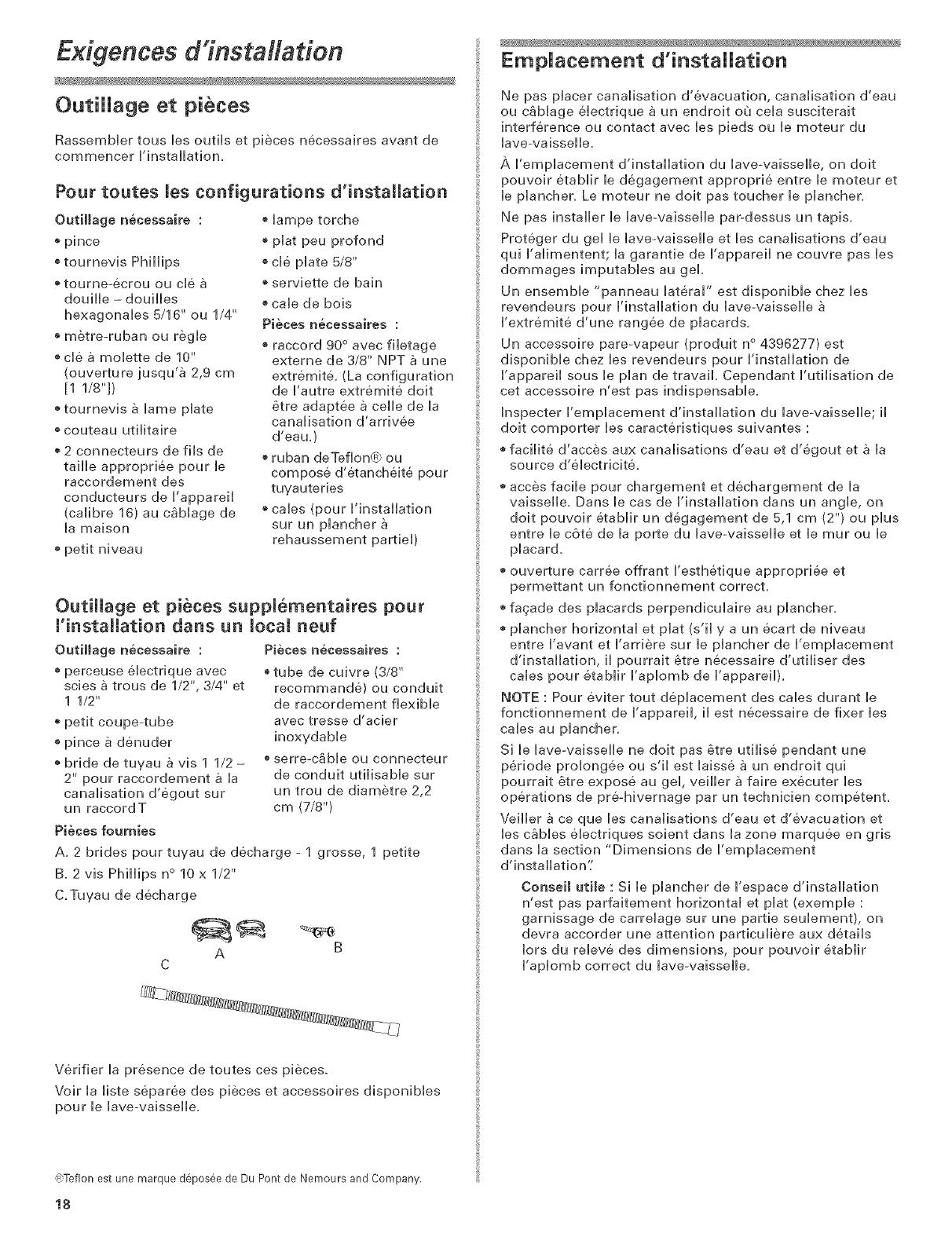
Pieces fournies
Pieces n@cessaires :
®tube de cuivre (3/8"
recommande} ou conduit
de raccordement flexible
avec tresse d'acier
inoxydable
o serreoc_ble ou connecteur
de conduit utilisable sur
un trou de diametre 2,2
cm (7/8"}
A. 2 brides pour tuyau de decharge - 1 grosse, 1 petite
B. 2 vis Phillips n° 10 x 1/2"
C.Tuyau de decharge
A B
C
Verifier la presence de toutes ces pieces.
Voir la liste separ6e des pieces et accessoires disponibles
pour le lave-vaisselle.
@Teflonest une marque d_,pos6ede Du Pont de Nemours and Company.
18
EmpJacement d'instaHation
Ne pas placer canalisation d'evacuation, canalisation d'eau
ou cablage electrique a un endroit ou cela susciterait
interference ou contact avec les pieds ou le moteur du
lave-vaisselle.
A I'emplacement d'installation du laveovaisselle0 on doit
pouvoir etablir le degagement approprie entre le moteur et
le plancher. Le moteur ne doit pas toucher le plancher.
Ne pas installer le lave-vaisselle par_dessus un tapis.
Proteger du gel le lave°vaisselle et lea canalisations d'eau
qui I%limentent; la garantie de I'appareil ne couvre pas les
dommages imputables au gel.
Un ensemble "panneau lateral" est disponible chez les
revendeurs pour I'installation du laveovaisselle
I'extremite d'une rangee de placards.
Un accessoire pare-vapeur (produit n° 4396277} est
disponible chez les revendeurs pour I'installation de
I'appareil sous le plan de travail. Cependant I'utilisation de
cet accessoire n'est pas indispensable.
Inspecter I'emplacement d'installation du laveovaisselle; il
doit comporter les caracteristiques suivantes :
facilite d'acces aux canalisations d'eau et d'egout eta la
source d%lectricite.
acces facile pour chargement et dechargement de la
vaisselle. Dans le cas de I'installation dans un angle, on
doit pouvoir etablir un degagement de 5,1 cm (2"} ou plus
entre le c6te de la porte du lave-vaisselle et le tour ou le
placard.
ouverture carree offrant I'esthetique appropriee et
permettant un fonctionnement correct.
fagade des placards perpendiculaire au plancher.
plancher horizontal et plat (s'il y a un ecart de niveau
entre I'avant et I'arriere sur le plancher de I'emplacement
d'installation, il pourrait 6tre necessaire d'utiliser des
cales pour etablir I'aplomb de I'appareil}.
NOTE : Pour eviter tout deplacement des cabs durant le
fonctionnement de I'appareil, il eat necessaire de fixer lea
cabs au plancher.
Si le lave-vaisselle ne doit pas _tre utilise pendant une
periode prolongee ou s'il est laisse a un endroit qui
pourrait 6tre expose au gel, veiller a faire executer lea
operations de pre-hivernage par un technicien competent.
Veiller ace que les canalisations d'eau et d'evacuation et
les cables electriques soient dans la zone marquee en gris
dana la section "Dimensions de I'emplacement
d'installation'[
Conseil utile : Si le plancher de I'espace d'installation
n'est pas parfaitement horizontal et plat (exemple :
garnissage de carrelage sur une pattie seulement}, on
devra accorder une attention particuliere aux details
Iors du releve des dimensions, pour pouvoir etablir
I'aplomb correct du laveovaisselle.


