Valcom V-A2412 Installation guide
- Category
- Wall clocks
- Type
- Installation guide
This manual is also suitable for

V-A2412 / V-A2416 Wired Clock
Installation Manual V1.05
Valcom, Inc.
5614 Hollins Road
Roanoke, VA 24019
540-563-2000 P.
540-362-9800 F.
www.valcom.com

2
Valcom, Inc.
5614 Hollins Road
Roanoke, VA 24019
540-563-2000 P.
540-362-9800 F.
www.valcom.com
Table of Contents
V-A2412/V-D2416 Wired Clock
*manuals may change without prior notice
Table of Contents—2
Wall Mount Installation —3
Metal Double Mount Installation —4
Plastic Double Mount Installation —5
Plastic Double Mount Installation—6
Plastic Double Mount Installation—7
2 Wire Digital Communication Wiring Information—8
3 Wire Synchronous (Sync-Wire) Communication 24 Volt Wiring Information—9
3 Wire Synchronous (Sync-Wire) Communication 110 Volt Wiring Information—10
Frequently Asked Questions—11
Troubleshooting—12
Diagnostic Testing - Overview—13
Diagnostic #1 - Protocol Verification—13
Diagnostic #2 - Comprehensive Test—14
Diagnostic #3 - Manufacturing Default—15
Compliances—16

3
Valcom, Inc.
5614 Hollins Road
Roanoke, VA 24019
540-563-2000 P.
540-362-9800 F.
www.valcom.com
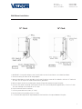
1. IMPORTANT: If using a low voltage system (24 volt) make sure that the transformer is an isolated transformer.
2. Connect the wiring as shown on the wiring diagram.
3. Mount the back plate to a single gang box using the two (2) machine screws #6-32 included in the kit for 12” clock and
16” clock. The 16” requires the screw to connect to the ground wire.
4. Mount the plastic anchor into the back plate, through the large hole, towards the top of the plate.
5. Insert the sheet metal screw (#10) into the plastic anchor. The screw should protrude approximately 1” for the 12” clock.
The screw should go in all the way for the 16” clock.
6. Plug the connector into the movement.
7. Insert the ground tab into the clock (12” clock).
8. Hang the clock on the protruding screw (12” clock).
9. Put screw #4-20 through hole on top and bottom of clock into hole at the top and bottom of the plate.
Wall Mount Installation
12” Clock 16” Clock

4
Valcom, Inc.
5614 Hollins Road
Roanoke, VA 24019
540-563-2000 P.
540-362-9800 F.
www.valcom.com
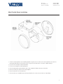
1. Screw the mounting bracket to the double gang box using four (4) inner holes on the mounting bracket, or mount the
mounting bracket directly to the wall or ceiling using the four (4) outer holes. (As shown in above drawing)
2. Insert the wires through the mounting bracket.
3. Fish the wires through the clock hanging rod.
4. Secure hanging rod to mounting bracket with screws supplied, and place cover over connection.
5. Connect the wiring as shown on the wiring diagrams.
6. Plug the connectors into the movements.
7. Place the clocks on the double mount housing and tighten the screws to secure clocks as shown above.
Metal Double Mount Installation

5
Valcom, Inc.
5614 Hollins Road
Roanoke, VA 24019
540-563-2000 P.
540-362-9800 F.
www.valcom.com
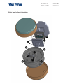
Plastic Double Mount Installation
q
w
e
r
y
y
t
y
Ethernet
Bracket
y
e

6
Valcom, Inc.
5614 Hollins Road
Roanoke, VA 24019
540-563-2000 P.
540-362-9800 F.
www.valcom.com
Plastic Double Mount Installation
q
Install metal mounting bracket - First, remove the metal mounting bracket from the inside of the double mount base by unscrewing
the two (2) 6-32 x 1/2” screws located on the underside of the base (save these screws for step #3). Next, screw the metal mounting
bracket to the wall or ceiling in which the clocks are being installed. To mount to the switch box, screw the four (4) 6-32 x 1” screws
supplied in the assembly kit through the inner four holes of the metal mounting bracket to the wall or ceiling. Use the outer four holes
to mount anchors to the wall or ceiling (both anchors and screws for anchors not supplied in kit). For IP clocks, if using an Ethernet
bracket (*as shown in the diagram) use the two (2) 6-32 x 1/4” included in the assembly kit to mount the Ethernet bracket to the metal
mounting bracket (Ethernet bracket not supplied in assembly kit).
Note: if using a plastic switch box, a ground wire must be routed through the switch box and into one (1) of
the four (4) metal mounting bracket screws in order to provide ground to the metal mounting bracket.
Note: the metal mounting bracket
MUST
be secured by both the screws going to the switch box
AND
the
anchors going into the wall.
w
Feed wiring through base and pole - Take the wiring coming from the switch box and begin to feed it through the center of the
base of the mounting assembly until it emerges from the hole in the center of the clock adaptor. Make sure there is roughly 1.5’ - 2’
of wiring coming from the switch box. Perform this task for both clocks. If installing IP clocks, run bare Ethernet wire without an RJ45
connector and install the connector after it has been routed through the clock if possible (this will be much easier than running the
wire with the connector on). If not possible, make sure that there is no boot present on the connector to run the wire through the
assembly. If you are using an Ethernet bracket with the installation of IP clocks, the assembly of the clocks in steps 4 through 6 can be
accomplished before mounting the assembly to the wall in step 3 - making the overall installation more simple.
Note: if the installer wishes to adjust the distance between the clock adaptor and the base of the double
mount, this can be accomplished by removing the adaptors from the double mount pole and choosing a
different hole on the double mount pole to route the wiring through before mounting to the wall.
e
Snap and screw base to metal mounting bracket - Snap the base to the metal mounting bracket by first making contact with the
lip in the upper side of the base and the metal mounting bracket. When the base has been snapped onto the bracket, take the two (2)
6-32 x 1/2” pan head screws that originally came installed on the base of the mounting assembly and screw them back into the two
holes on the underside of the base to secure the base to the metal mounting bracket.
r
Connect switch box wires to clock harness - Take the wiring harness supplied with the clock and make all necessary connections
between the wiring harness and the switch box wires using wire nuts. Perform this task for both clocks.
*For metal mounting bracket: Use anchor that can support 50 lbs with a maximum screw size of 10/1.5”
*instructions continued on next page

7
Valcom, Inc.
5614 Hollins Road
Roanoke, VA 24019
540-563-2000 P.
540-362-9800 F.
www.valcom.com
t
Plug and secure wiring to clock - Loosen and slip excess wiring through provided wire clamp (comes attached to each clock adaptor) and
tighten the clamp. After securing excess wiring, plug the jack at the end of the wiring into the appropriate jack on the back of the clock. If
using IP clocks, wiring will not be supplied with the clocks - the installer will be responsible for supplying all Ethernet wiring.
y
Attach and screw clocks to adaptors - Find all four (4) tabs located on each adaptor. Snap the clock onto the adaptor, making sure all
four (4) tabs on the adaptor are secured to the clock (if installing battery powered clocks, make sure batteries are installed at this point).
After securing the clock to the adaptor with the tabs, the clock should be able to rotate 5 degrees left and right. Rotate to align the clocks
with the ceiling or wall. Secure its position by using the four (4) 6-19 x 7/16” screws that come attached to the clock adaptor from the factory
and screw them into the four (4) tabs on the adaptor.
Plastic Double Mount Installation

8
Valcom, Inc.
5614 Hollins Road
Roanoke, VA 24019
540-563-2000 P.
540-362-9800 F.
www.valcom.com
Wiring Information
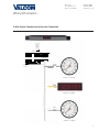
2 Wire Digital Communication System Connection
110V
(EU 240V)
White
Black
White
Black
V-D2425 or V-D2440
V-A2412 or V-A2416
V-CCU
V-C6124P
+ - + - + -
24 volt outputs
+ - + - + -
24 V DC IN
DATA IN
19
18
2 W ire Digital
Output to Clocks
V-C6124P and the V-CCU
are ordered as a V-VCU
18 19
*V-C6124P and the V-CCU are ordered as
a V-VCU
V-A2412 or V-A2416

9
Valcom, Inc.
5614 Hollins Road
Roanoke, VA 24019
540-563-2000 P.
540-362-9800 F.
www.valcom.com
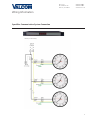
Wiring Information
10 Amp Contact Rating
Sync-Wire Communication System Connection

10
Valcom, Inc.
5614 Hollins Road
Roanoke, VA 24019
540-563-2000 P.
540-362-9800 F.
www.valcom.com
Frequently Asked Questions
Can the V-A2412 or V-A2416 clock run using a V-D11025 or V-D11040 digital clock as a master?
Yes, a V-D11025 or V-D11040 digital clock can run a V-A2412 or V-A2416 clock.
What happens if clocks are connected to power but the master clock has not been connected?
When power is applied, the clocks will run, but will not show the correct time. When the master clock is installed and connected, the V-A2412 or
V-A2416 clocks will receive a correction signal from the master clock and will reset themselves to show the correct time.
Can the clocks be set manually to display the correct time at installation (as a temporary measure until the master clock is installed)?
V-A2412 or V-A2416 clocks can NOT be set manually.
Do I have to reset the clock if a power failure occurs?
No, there is no need to reset the clock after power failure. When the power resumes, the V-A2412 or V-A2416 clocks will resume normal operation.
Upon receipt of correction signals from the master clock, the V-A2412 or V-A2416 clock will reset itself within a short time to display the proper
time.
How do I choose the proper protocol?
There is no need to set jumpers or choose a protocol. V-A2412 or V-A2416 clocks automatically detects the correct protocol of the system and they
will adjust themselves accordingly.
Can I change protocols after the system is already running?
Yes, if you desire to change protocols one of two options may be used:
Plug the V-A2412 or V-A2416 clock to the new protocol scheme and within three (3) days, the clocks will automatically detect the change and adapt
themselves accordingly.
Perform Diagnostic #3 to bring the clocks to manufacturers default; please see page 14 for complete details and instructions.
What size back box is needed?
A standard single gang box is required for wall mounting, and a standard double gang box for double mount clocks.
What does the LED on the back of the movement signify?
The LED allows the user to view diagnostics, as well as view if the clock is getting data. If the clock is receiving communication via 2 wire digital
communication or 3 wire digital communication, the LED will flicker indicating it is receiving the data. If the user is using a synchronous protocol,
the LED will turn solid red when the correction is put on the reset line. When diagnostics are being performed, the LED shows which diagnostic is
being performed and if the clock passes the diagnostic. Please see pages 12 - 14 for more information on diagnostics.
Support

11
Valcom, Inc.
5614 Hollins Road
Roanoke, VA 24019
540-563-2000 P.
540-362-9800 F.
www.valcom.com
Troubleshooting
The clock is not running. What do I do?
a) Make sure the pin is removed.
b) Measure the voltage between the (black) power wire and the (white) neutral wire. For 24 volt models, the voltage should measure 14 - 28 VAC,
unless the 2 wire digital communication system is being implemented. Then the meter should read a pulsating 24 volts DC. For 110 volt models,
the meter should read 85 - 135 VAC.
c) Make sure the ground wire is not touching other wires.
The clock is not receiving a reset signal from the master clock. What do I do?
Check the red diagnostic LED on the back of the movement (do NOT push the switch). If the red LED is off, no data is detected in the clock. If the
red LED is blinking once per second, data is detected in the clock in the right polarity (2 or 3 wire digital communication systems). If the red LED
is on, then the voltage is presently on the reset line (synchronous systems). If the red LED continues to be on steadily, please contact technical
support.
In order to verify the last time the clock received communication from the master, a Diagnostic #2 can be performed; please see page 13 for
complete details.
In order to verify that the clock detects the right protocol, perform Diagnostic #1; please see page 12 for complete details.
The clocks sometimes show the wrong time. What do I do?
Perform Diagnostic #2; please see page 13 for complete details and instructions.
I’m running the synchronous system, and the red LED is always on in the back. What does that mean?
Check to make sure that the reset line is not shorted to the power. Also, make sure that there is no leakage on the reset line. Measure the voltage
between the reset and the neutral. It should be reading 0 volts AC & DC when the clock is not in correction.
Support

12
Valcom, Inc.
5614 Hollins Road
Roanoke, VA 24019
540-563-2000 P.
540-362-9800 F.
www.valcom.com
Diagnostic Testing - Overview
To enter the diagnostic testing, press the diagnostic switch located on the right hand side of the movement, or use a master clock to send the
diagnostic tests to the V-A2412 or V-A2416 clocks. (Please refer to your specific master clock’s installation manual for complete details and
instructions.)
Diagnostic #1 - Protocol Verification
Purpose: To display the type of protocol the master clock is sending.
Holding the switch for 1 second will enable you to enter into Diagnostic #1. This can be verified by the green diagnostic LED flashing 1 time with a
3 second break between flashes.
While the clock is performing the diagnostic, the diagnostic LED will continue to flash green. If a problem is diagnosed by the clock, the flashing
green LED will turn into a flashing red LED. In this case, please refer to Table 2 for the diagnostic error codes. If at the end of the diagnostic, the
diagnostic LED changes to solid green, the test was completed successfully.
At the end of diagnostic, the second hand will display the type of protocol the master clock is sending; please refer to Table 1. This will be
displayed for approximately 3 minutes, then the clock will begin to run normally.
Table 1
Hand Position Protocol and Polarity Detected
2 seconds 2-Wire Digital Communication, Polarity 1
4 seconds 2-Wire Digital Communication, Polarity 2
14 seconds 59 Minute Correction, Correct Polarity
16 seconds 59 Minute Correction, Reverse Polarity
18 seconds 58 Minute Correction, Correct Polarity
20 seconds 58 Minute Correction, Reverse Polarity
22 seconds National Time/Rauland Correction, Correct Polarity
24 seconds National Time/Rauland Correction, Reverse Polarity
Diagnostic Testing

13
Valcom, Inc.
5614 Hollins Road
Roanoke, VA 24019
540-563-2000 P.
540-362-9800 F.
www.valcom.com
Diagnostic #2 - Comprehensive Test
Purpose: To test the gearbox and electrical components.
The second hand will display the protocol that was detected, the minute hand will display the software version number, and the hour hand will
display how much time has passed since the clock last received communication signal.
Holding the switch for 3 seconds will enable you to enter into diagnostic #2. This can be verified by the green diagnostic LED flashing 2 times with
a 3 second break between flashes.
While the clock is performing the diagnostic, the diagnostic LED will continue to flash green. If a problem is diagnosed by the clock, the flashing
green LED will turn into a flashing red LED. In this case, please refer to Table 2 for the diagnostic error codes. If at the end of the diagnostic the
diagnostic LED changes to solid green, the test was completed successfully.
At the end of Diagnostic #2
The second hand will display the protocol that was detected. Please refer to Table 1.
The minute hands will display the software version number.
The hour hand will display how much time has passed since the clock last received a communication signal; please refer to Table 2. This will be
displayed for approximately 3 minutes, then the clock will begin to run normally.
Table 2
Hand Position Time Since the Clock Last Received Communication
12 Clock received communication within the last hour
1 Clock received communication between one and two hours ago
2 Clock received communication between two and three hours ago
3 Clock received communication between three and four hours ago
4 Clock received communication between four and five hours ago
5 Clock received communication between five and six hours ago
6 Clock received communication between six and seven hours ago
7 Clock received communication between seven and eight hours ago
8 Clock received communication between eight and nine hours ago
9 Clock received communication between nine and ten hours ago
10 Clock received communication between ten and eleven hours ago
11 Clock received communication more than eleven hours ago - May signify a manufacturer default
Diagnostic Testing

14
Valcom, Inc.
5614 Hollins Road
Roanoke, VA 24019
540-563-2000 P.
540-362-9800 F.
www.valcom.com
Diagnostic #3 - Manufacturing Default
Purpose: To bring the clock to 12:00:00 and reset to manufacturer’s default.
Holding the switch for 5 seconds will enable you to enter into Diagnostic #3. This can be verified by the green diagnostic LED flashing 3 times with
a five (5) second break between flashes.
While the clock is performing the diagnostic, the diagnostic LED will continue to flash green. If a problem is diagnosed by the clock, the flashing
green LED will turn into a flashing red LED. In this case, please refer to Table 3 for the diagnostic error codes. If at the end of the diagnostic the
diagnostic LED changes to solid green, the test was completed successfully.
At the end of Diagnostic #3 the hands will all be set to 12:00:00. The V-A2412 or V-A2416 clocks will not resume normal operation until the power
has been recycled.
Table 3
Number of Red Flashes Diagnosis of Error Code
1,2 Movement detected problem with second hand. Check hands to see if they are hitting each other. Repeat test.
3,4,5 Movement detected problem with hour/minute hand. Check to see if they are hitting each other. Repeat test.
6,7,8 Call Tech Support
Diagnostic Testing

15
Valcom, Inc.
5614 Hollins Road
Roanoke, VA 24019
540-563-2000 P.
540-362-9800 F.
www.valcom.com
This equipment has been tested and found to comply with the limits for a Class B digital device, pursuant to part 15 of the FCC Rules. These
limits are designed to provide reasonable protection against harmful interference in a residential installation. This equipment generates, uses and
can radiate radio frequency energy and, if not installed and used in accordance with the instructions, may cause harmful interference to radio
communications. However, there is no guarantee that interference will not occur in a particular installation. If this equipment does cause harmful
interference to radio or television reception, which can be determined by turning the equipment off and on, the user is encouraged to try to correct
the interference by one or more of the following measures:
1. Reorient or relocate the receiving antenna.
2. Increase the separation between the equipment and receiver.
3. Connect the equipment into an outlet on a circuit different from that to which the receiver is connected.
4. Consult the dealer or an experienced radio/TV technician for help.
Compliances
FCC Statement: Information to the user (for U.S. only)
IC Statement (for Canada only)
This Class B digital apparatus complies with Canadian ICES-003.
CET appareil numérique de la classe B est conforme á la norme NMB-003 du Canada.
The user is cautioned that any changes or modifications not expressly approved by the party responsible for compliance could void the user’s
authority to operate the equipment.
This unit was tested with shielded cables on the peripheral devices. Shielded cables must be used with the unit to ensure compliance.
CE Declaration of Conformity
We, The Sapling Company certify and declare under our sole responsibility that the SMA 3000 conforms with the essential requirements of the EMC
Directive 2004/108.EC and LVD 2006/95/EC, based on the following standards applied:
EN 55022: 2006
EN 61000-3-2: 2006
EN 61000-3-3: 1995 /A1: 2001 /A2:2005
EN 55024 : 1998 /A1:2001, A2:2003
EN 60950-1:2006 - Safety Part 1
FCC Part 15b Industry Canada
-
 1
1
-
 2
2
-
 3
3
-
 4
4
-
 5
5
-
 6
6
-
 7
7
-
 8
8
-
 9
9
-
 10
10
-
 11
11
-
 12
12
-
 13
13
-
 14
14
-
 15
15


Valcom V-A2412 Installation guide
- Category
- Wall clocks
- Type
- Installation guide
- This manual is also suitable for
Ask a question and I''ll find the answer in the document
Finding information in a document is now easier with AI
Related papers
-
Valcom Wireless Digital Installation guide
-
-
-
-
-
-
-
-
-
Other documents
-
ThunderStruck-EV ThunderStruck-EV Chevy Volt DC-DC Converter User guide
-
Bosch VCUNM1 User manual
-
 Pure Air 2000HS PLUS Installation Instructions Manual
-
 Edwards Signaling 24A715M User manual
-
Sapling SAA Series Installation guide
-
-
-
-
-
 Simplex 6310-9221A Quick start guide


