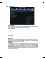
Gigabyte GA-F2A88X-UP4 (rev. 3.0) User manual
- Category
- Motherboards
- Type
- User manual

GA-F2A88X-UP4
User's Manual
Rev. 3001
12ME-F288XP4-3001R

Motherboard
GA-F2A88X-UP4
Aug. 26, 2013
Aug. 26, 2013
Motherboard
GA-F2A88X-UP4

Copyright
©
2013 GIGA-BYTE TECHNOLOGY CO., LTD. All rights reserved.
The trademarks mentioned in this manual are legally registered to their respective owners.
Disclaimer
Information in this manual is protected by copyright laws and is the property of GIGABYTE.
Changes to the specications and features in this manual may be made by GIGABYTE
without prior notice.
No part of this manual may be reproduced, copied, translated, transmitted, or published in
any form or by any means without GIGABYTE's prior written permission.
Documentation Classications
In order to assist in the use of this product, GIGABYTE provides the following types of docu-
mentations:
For quick set-up of the product, read the Quick Installation Guide included with the product.
For detailed product information, carefully read the User's Manual.
For product-related information, check on our website at: http://www.gigabyte.com
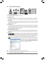
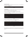
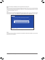
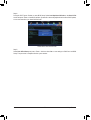
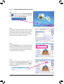
Identifying Your Motherboard Revision
The revision number on your motherboard looks like this: "REV: X.X." For example, "REV:
1.0" means the revision of the motherboard is 1.0. Check your motherboard revision before
updating motherboard BIOS, drivers, or when looking for technical information.
Example:

- 4 -
Table of Contents
Box Contents ...................................................................................................................6
Optional Items .................................................................................................................6
GA-F2A88X-UP4 Motherboard Layout ...........................................................................7
GA-F2A88X-UP4 Motherboard Block Diagram ..............................................................8
Chapter 1 Hardware Installation .....................................................................................9
1-1 Installation Precautions ................................................................................... 9
1-2 ProductSpecications ................................................................................... 10
1-3 Installing the CPU and CPU Cooler............................................................... 13
1-3-1 Installing the APU ..................................................................................................13
1-3-2 Installing the APU Cooler ......................................................................................15
1-4 Installing the Memory .................................................................................... 16
1-4-1 DualChannelMemoryConguration ....................................................................16
1-4-2 Installing a Memory ................................................................................................17
1-5 Installing an Expansion Card ......................................................................... 18
1-6 SetupoftheAMDDualGraphicsConguration ........................................... 19
1-7 Setting up AMD CrossFire
™
Conguration .................................................... 20
1-8 Back Panel Connectors ................................................................................. 21
1-9 Internal Connectors ....................................................................................... 24
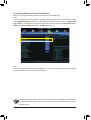
Chapter 2 BIOS Setup ..................................................................................................33
2-1 Startup Screen ............................................................................................... 34
2-2 The Main Menu .............................................................................................. 35
2-3 M.I.T. .............................................................................................................. 37
2-4 System Information ........................................................................................ 45
2-5 BIOS Features ............................................................................................... 46
2-6 Peripherals ..................................................................................................... 49
2-7 Power Management ....................................................................................... 52
2-8 Save & Exit .................................................................................................... 54

- 5 -
Chapter3 ConguringSATAHardDrive(s) ..................................................................55
3-1 ConguringSATAControllers ........................................................................ 55
3-2 Installing the SATA RAID/AHCI Driver and Operating System ..................... 64
Chapter 4 Drivers Installation .......................................................................................69
4-1 Installing Chipset Drivers ............................................................................... 69
4-2 Application Software ...................................................................................... 70
4-3 Technical Manuals ......................................................................................... 70
4-4 Contact........................................................................................................... 71
4-5 System ........................................................................................................... 71
4-6 Download Center ........................................................................................... 72
Chapter 5 Unique Features...........................................................................................73
5-1 BIOS Update Utilities ..................................................................................... 73
5-1-1 Updating the BIOS with the Q-Flash Utility ...........................................................73
5-1-2 Updating the BIOS with the @BIOS Utility ............................................................76
5-2 EasyTune 6 .................................................................................................... 77
5-3 Smart Recovery 2 .......................................................................................... 78
Chapter 6 Appendix ......................................................................................................81
6-1 ConguringAudioInputandOutput .............................................................. 81
6-1-1 Conguring2/4/5.1/7.1-ChannelAudio ..................................................................81
6-1-2 ConguringS/PDIFOut ........................................................................................ 83
6-1-3 ConguringMicrophoneRecording ...................................................................... 84
6-1-4 Using the Sound Recorder ................................................................................... 86
6-2 Troubleshooting ............................................................................................. 87
6-2-1 Frequently Asked Questions..................................................................................87
6-2-2 Troubleshooting Procedure .................................................................................. 88
6-3 Debug LED Codes .........................................................................................90
Regulatory Statements ............................................................................................. 94
Contact Us ................................................................................................................ 95

- 6 -
Box Contents
5
GA-F2A88X-UP4 motherboard
5
Motherboard driver disk
5
User's Manual
5
Quick Installation Guide
5
Six SATA cables
5
I/O Shield
Optional Items
2-portUSB2.0bracket(PartNo.12CR1-1UB030-6*R)
eSATAbracket(PartNo.12CF1-3SATPW-4*R)
3.5"FrontPanelwith2USB3.0/2.0ports(PartNo.12CR1-FPX582-2*R)
HDMI-to-DVIadapter(PartNo.12CT2-HDMI01-1*R)
COMportcable(PartNo.12CF1-1CM001-3*R)
The box contents above are for reference only and the actual items shall depend on the product package you obtain.
The box contents are subject to change without notice.

- 7 -
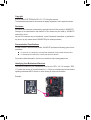
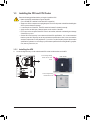
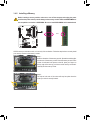
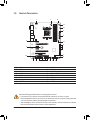
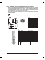
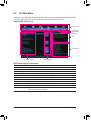
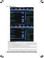
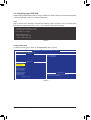
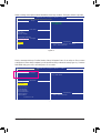
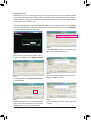
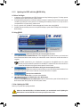
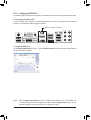
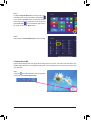
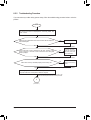
GA-F2A88X-UP4 Motherboard Layout
KB_MS_USB3
CPU_FAN
SYS_FAN1
Socket FM2+
ATX
F_USB30_1
AUDIO
DDR3_4
DDR3_2
DDR3_3
DDR3_1
BAT
ATX_12V
AMD A88X
CODEC
CLR_CMOS
VIA
®
VL805
M_BIOS
DB_PORT
(Note)
B_BIOS
DVI_VGA
USB30_LAN
Realtek
®
GbELAN
PCIEX16
PCIEX1_2
PCIEX4
PCI
PCIEX1_3
SYS_FAN3
RST_SW
PW_SW
CMOS_SW
iTE
®
Super I/O
GA-F2A88X-UP4
DP_HDMI_SPDIF
USB_ESATA
F_PANEL
SYS_FAN2
F_USB1 F_USB30_2F_USB3 F_USB2F_USB4F_AUDIO
SPDIF_O
COM
PCIEX1_1
PCIEX8
SATA3
SATA3
SATA3
SATA3
2
1
0
4
3
6
5
(Note) Fordebugcodeinformation,pleaserefertoChapter6.

- 8 -
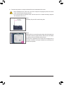
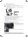
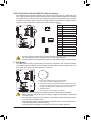
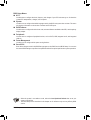
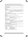
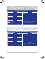
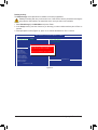
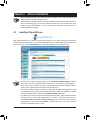
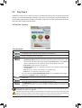
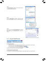
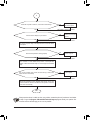
GA-F2A88X-UP4 Motherboard Block Diagram
Fordetailedproductinformation/limitation(s),referto"1-2ProductSpecications."
AMD APU
UMI
APUCLK+/-(100MHz)
Dual Channel Memory
PCI Express Bus
PCI Express Bus
COM
LPC
Bus
1 PCI
PCI Bus
Dual BIOS
PCI CLK
(33MHz)
PCIe CLK
(100MHz)
PS/2 KB/Mouse
10 USB 2.0/1.1
4 USB 3.0/2.0
LAN
RJ45
x1
x1x1
x1x4
x1
Realtek
®
GbELAN
2 PCI Express x1
(PCIEX1_1/PCIEX1_2)
1 PCI Express x16
2 PCI Express x8
Switch
or
or
x16 x16
2 USB 3.0/2.0
VIA
®
VL805
HDMI
7 SATA 6Gb/s
1 eSATA
AMD A88X
DISPCLK+/-(100MHz)
DDR32133/1866/1600/1333MHz
DVI-D
DisplayPort
D-Sub
Switch
iTE
®
Super I/O
2 PCI Express x1
(PCIEX4/PCIEX1_3)
1 PCI Express x4
Switch
Line Out
MIC
Line In
S/PDIF Out
Side Speaker Out
CODEC
Center/Subwoofer
Speaker Out
Rear Speaker Out

- 9 -
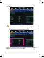
Hardware Installation
1-1 Installation Precautions
The motherboard contains numerous delicate electronic circuits and components which can become
damagedasaresultofelectrostaticdischarge(ESD).Priortoinstallation,carefullyreadtheuser's
manual and follow these procedures:
• Prior to installation, make sure the chassis is suitable for the motherboard.
• Prior to installation,do notremove or breakmotherboard S/N (SerialNumber) stickeror
warranty sticker provided by your dealer. These stickers are required for warranty validation.
• Always remove the AC power by unplugging the power cord from the power outlet before
installing or removing the motherboard or other hardware components.
• Whenconnectinghardwarecomponentstotheinternalconnectorsonthemotherboard,make
sure they are connected tightly and securely.
• Whenhandlingthemotherboard,avoidtouchinganymetalleadsorconnectors.
• Itisbesttowearanelectrostaticdischarge(ESD)wriststrapwhenhandlingelectroniccom-
ponents such as a motherboard, CPU or memory. If you do not have an ESD wrist strap, keep
yourhandsdryandrsttouchametalobjecttoeliminatestaticelectricity.
• Prior to installing the motherboard, please have it on top of an antistatic pad or within an
electrostatic shielding container.
• Before unplugging the power supply cable from the motherboard, make sure the power supply
has been turned off.
• Before turning on the power, make sure the power supply voltage has been set according to
the local voltage standard.
• Before using the product, please verify that all cables and power connectors of your hardware
components are connected.
• To prevent damage to the motherboard, do not allow screws to come in contact with the
motherboard circuit or its components.
• Make sure there are no leftover screws or metal components placed on the motherboard or
within the computer casing.
• Do not place the computer system on an uneven surface.
• Do not place the computer system in a high-temperature environment.
• Turning on the computer power during the installation process can lead to damage to system
components as well as physical harm to the user.
• If you are uncertain about any installation steps or have a problem related to the use of the
product,pleaseconsultacertiedcomputertechnician.
Chapter 1 Hardware Installation

- 10 -
Hardware Installation
1-2 ProductSpecications
APU FM2+ Socket:
- AMD A series processors
- AMD Athlon
™
series processors
(GotoGIGABYTE'swebsiteforthelatestCPUsupportlist.)
Chipset AMD A88X
Memory 4 x 1.5V DDR3 DIMM sockets supporting up to 64 GB of system memory
* DuetoaWindows32-bitoperatingsystemlimitation,whenmorethan4GBofphysical
memoryisinstalled,theactualmemorysizedisplayedwillbelessthanthesizeof
the physical memory installed.
* Themaximum64GBofsystemmemorycanbesupportedusing16GB(orabove)
memorymodules. GIGABYTEwillupdatethememory supportlistonthe ofcial
website when the memory modules are available on the market.
Dual channel memory architecture
SupportforDDR32133/1866/1600/1333MHzmemorymodules
SupportforAMDMemoryProle(AMP)/ExtremeMemoryProle(XMP)memory
modules
(GotoGIGABYTE'swebsiteforthelatestsupportedmemoryspeedsandmemory
modules.)
Onboard
Graphics
APU with integrated AMD Radeon
™
HD 8000/7000 series graphics:
* Tousetheonboardgraphicsports,youmustinstallanAMDAPUwithintegrated
graphics.
- 1 x D-Sub port, supporting a maximum resolution of 1920x1200
- 1 x DVI-D port, supporting a maximum resolution of 2560x1600
* Supportfor2560x1600resolutionrequiresbothamonitorandcablethatsupport
Dual Link DVI.
* TheDVI-DportdoesnotsupportD-Subconnectionbyadapter.
- 1 x HDMI port, supporting a maximum resolution of 4096x2160
* Theresolutionof 4096x2160 can be supported when using an FM2+APU; the
maximum resolution supported is 1920x1200 when using an FM2 APU.
* SupportforHDMI1.4aversion.
- 1 x DisplayPort, supporting a maximum resolution of 4096x2160
* TheDisplayPortdoesnotsupportHotplug.Ifyouwanttochangetoanothergraphics
portwhenthecomputerison,besuretoturnoffthecomputerrst.
* SupportforDisplayPort1.2version.
- Maximum shared memory of 2 GB
Audio Realtek
®
ALC892 codec
HighDenitionAudio
2/4/5.1/7.1-channel
Support for S/PDIF Out
LAN Realtek
®
GbELANchip(10/100/1000Mbit)
Expansion Slots 1xPCIExpressx16slot,runningatx16(PCIEX16)
* Foroptimumperformance,ifonlyonePCIExpressgraphicscardistobeinstalled,
be sure to install it in the PCIEX16 slot.
1xPCIExpressx16slot,runningatx8(PCIEX8)
* ThePCIEX8slotsharesbandwidthwiththePCIEX16slot.WhenthePCIEX8slot
is populated, the PCIEX16 slot will operate at up to x8 mode.
(ThePCIEX16andPCIEX8slotsconformtoPCIExpress3.0standard.)
* TosupportPCIExpress3.0,youmustinstallanFM2+APU.

- 11 -
Hardware Installation
Expansion Slots 1xPCIExpressx16slot,runningatx4(PCIEX4)
* ThePCIEX1_3slotsharesbandwidthwiththePCIEX4slot.WhenthePCIEX1_3
slot is populated, the PCIEX4 slot will operate at up to x1 mode.
3 x PCI Express x1 slots
(ThePCIEX4andPCIExpressx1slotsconformtoPCIExpress2.0standard.)
1 x PCI slot
Multi-Graphics
Technology
Support for AMD CrossFire
™
technology(PCIEX16andPCIEX8)
Support for AMD Dual Graphics technology
* OnlyAseriesAPUssupportAMDDualGraphics.
Storage Interface Chipset:
- 7xSATA6Gb/sconnectors(SATA30~6)
- 1 x eSATA connector on the back panel
* Actualtransferrateisdependentonthedevicebeingconnected.
- Support for RAID 0, RAID 1, RAID 5, RAID 10, and JBOD
USB Chipset:
- 4USB3.0/2.0ports(availablethroughtheinternalUSBheaders)
- 10USB2.0/1.1ports(2portsonthebackpanel,8portsavailablethrough
theinternalUSBheaders)
VIA
®
VL805 chip:
- 4 USB 3.0/2.0 ports on the back panel
Internal
Connectors
1 x 24-pin ATX main power connector
1 x 8-pin ATX 12V power connector
7 x SATA 6Gb/s connectors
1 x APU fan header
3 x system fan headers
1 x front panel header
1 x front panel audio header
1 x S/PDIF Out header
2 x USB 3.0/2.0 headers
4 x USB 2.0/1.1 headers
1 x serial port header
1 x Clear CMOS jumper
1 x power button
1 x reset button
1 x Clear CMOS button
Back Panel
Connectors
1 x PS/2 keyboard/mouse port
1 x D-Sub port
1 x DVI-D port
1 x optical S/PDIF Out connector
1 x HDMI port
1 x DisplayPort
4 x USB 3.0/2.0 ports
2 x USB 2.0/1.1 ports
1 x eSATA connector
1 x RJ-45 port
6xaudiojacks(Center/SubwooferSpeakerOut,RearSpeakerOut,SideSpeaker
Out,LineIn,LineOut,MicIn)

- 12 -
Hardware Installation
I/O Controller iTE
®
I/O Controller Chip
Hardware
Monitor
System voltage detection
APU/System temperature detection
APU/System fan speed detection
APU overheating warning
APU/System fan fail warning
APU/System fan speed control
* Whether the fan speed control function is supported will depend on the cooler you
install.
BIOS 2 x 64 Mbit ash
Use of licensed AMI EFI BIOS
Support for DualBIOS
™
PnP 1.0a, DMI 2.0, SM BIOS 2.6, ACPI 2.0a
Unique Features Support for @BIOS
Support for Q-Flash
Support for Xpress Install
Support for EasyTune
* Available functions in EasyTune may differ by motherboard model.
Support for Smart Recovery 2
Support for ON/OFF Charge
Bundled
Software
Norton
®
Internet Security (OEM version)
Operating
System
Support for Windows 8.1/8/7 32-bit/64-bit
* If you plan to install Windows 8.1, please download the latest drivers from GIGABYTE's
website.
Support for Windows XP 32-bit
* To support Windows XP 32-bit, you must install an AMD FM2 Trinity APU.
Form Factor ATX Form Factor; 30.5cm x 24.4cm
* GIGABYTE reserves the right to make any changes to the product specications and product-related information without
prior notice.
* Please visit the Support & Downloads\Utility page on GIGABYTE's website to check the supported operating system(s)
for the software listed in the "Unique Features" and "Bundled Software" columns.

- 13 -
Hardware Installation
1-3 Installing the CPU and CPU Cooler
Read the following guidelines before you begin to install the APU:
• Make sure that the motherboard supports the APU.
(GotoGIGABYTE'swebsiteforthelatestAPUsupportlist.)
• Always turn off the computer and unplug the power cord from the power outlet before installing the
APU to prevent hardware damage.
• Locate the pin one of the APU. The APU cannot be inserted if oriented incorrectly.
• Apply an even and thin layer of thermal grease on the surface of the APU.
• Do not turn on the computer if the APU cooler is not installed, otherwise overheating and damage
of the APU may occur.
• SettheAPUhostfrequencyinaccordancewiththeAPUspecications.Itisnotrecommended
thatthesystembusfrequencybesetbeyondhardwarespecicationssinceitdoesnotmeetthe
standard requirements for the peripherals. If you wish to set the frequency beyond the standard
specications,pleasedosoaccordingtoyourhardwarespecicationsincludingtheAPU,graphics
card, memory, hard drive, etc.
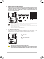
1-3-1 Installing the APU
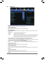
A. Locate the alignment keys on the motherboard APU socket and the notches on the APU.
APU
A Small Triangle Marking
Denotes APU Pin One
A Small Triangle Marking
Denotes Pin One of the
Socket
FM2+ Socket

- 14 -
Hardware Installation
B. Follow the steps below to correctly install the APU into the motherboard APU socket.
• Before installing the APU, make sure to turn off the computer and unplug the power cord from the
power outlet to prevent damage to the APU.
• DonotforcetheAPUintotheAPUsocket.TheAPUcannottiniforientedincorrectly.Adjustthe
APU orientation if this occurs.
Step 1:
Completely lift up the APU socket locking lever.
Step 2:
AligntheAPUpinone(smalltrianglemarking)withthetrianglemark
on the APU socket and gently insert the APU into the socket. Make
surethattheAPUpinstperfectlyintotheirholes.
OncetheAPUispositionedintoitssocket,placeonengerdownon
the middle of the APU, lowering the locking lever and latching it into
the fully locked position.
APU Socket
Locking Lever

- 15 -
Hardware Installation
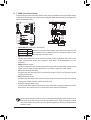
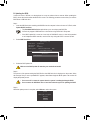
1-3-2 Installing the APU Cooler
Follow the steps below to correctly install the APU cooler on the motherboard.
Use extreme care when removing the APU cooler because the thermal grease/tape between the APU
cooler and APU may adhere to the APU. Inadequately removing the APU cooler may damage the APU.
Step 1:
Apply an even and thin layer of thermal grease on
the surface of the installed APU.
Step 2:
Hook the APU cooler clip to the mounting lug on
one side of the retention frame. On the other side,
push straight down on the APU cooler clip to hook
it to the mounting lug on the retention frame.
Step 4:
Finally, attach the power connector of the APU
coolertotheAPUfanheader(CPU_FAN)onthe
motherboard.
Step 3:
Turn the cam handle from the left side to the
rightside (as the pictureabove shows) to lock
intoplace.(RefertoyourAPUcoolerinstallation
manualforinstructionsoninstallingthecooler.)

- 16 -
Hardware Installation
1-4 Installing the Memory
Read the following guidelines before you begin to install the memory:
• Make sure that the motherboard supports the memory. It is recommended that memory of the same
capacity, brand, speed, and chips be used.
(GotoGIGABYTE'swebsiteforthelatestsupportedmemoryspeedsandmemorymodules.)
• Always turn off the computer and unplug the power cord from the power outlet before installing the
memory to prevent hardware damage.
• Memory modules have a foolproof design. A memory module can be installed in only one direction.
If you are unable to insert the memory, switch the direction.
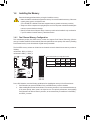
1-4-1 DualChannelMemoryConguration
This motherboard provides four DDR3 memory sockets and supports Dual Channel Technology. After the
memoryisinstalled,theBIOSwillautomaticallydetectthespecicationsandcapacityofthememory.Enabling
Dual Channel memory mode will double the original memory bandwidth.
The four DDR3 memory sockets are divided into two channels and each channel has two memory sockets as
following:
Channel A: DDR3_2, DDR3_4
Channel B: DDR3_1, DDR3_3
Due to APU limitations, read the following guidelines before installing the memory in Dual Channel mode.
1. Dual Channel mode cannot be enabled if only one DDR3 memory module is installed.
2. WhenenablingDualChannelmodewithtwoorfourmemorymodules,itisrecommendedthatmemory
of the same capacity, brand, speed, and chips be used. For optimum performance, when enabling
Dual Channel mode with two memory modules, we recommend that you install them in the DDR3_1
and DDR3_2 sockets.
DualChannelMemoryCongurationsTable:
(SS=Single-Sided,DS=Double-Sided,"--"=NoMemory)
DDR3_4
DDR3_2
DDR3_3
DDR3_1
DDR3_4 DDR3_2 DDR3_3 DDR3_1
Two Modules - - DS/SS - - DS/SS
DS/SS - - DS/SS - -
Four Modules DS/SS DS/SS DS/SS DS/SS

- 17 -
Hardware Installation
1-4-2 Installing a Memory
Before installing a memory module, make sure to turn off the computer and unplug the power
cord from the power outlet to prevent damage to the memory module. DDR3 and DDR2 DIMMs are
not compatible to each other or DDR DIMMs. Be sure to install DDR3 DIMMs on this motherboard.
ADDR3memorymodulehasanotch,soitcanonlytinonedirection.Followthestepsbelowtocorrectlyinstall
your memory modules in the memory sockets.
Step 1:
Notetheorientationofthememorymodule.Spreadtheretainingclips
at both ends of the memory socket. Place the memory module on the
socket.Asindicatedinthepictureontheleft,placeyourngerson
the top edge of the memory, push down on the memory and insert it
vertically into the memory socket.
Step 2:
The clips at both ends of the socket will snap into place when the
memory module is securely inserted.
Notch
DDR3 DIMM

- 18 -
Hardware Installation
1-5 Installing an Expansion Card
Read the following guidelines before you begin to install an expansion card:
• Make sure the motherboard supports the expansion card. Carefully read the manual that came
with your expansion card.
• Always turn off the computer and unplug the power cord from the power outlet before installing an
expansion card to prevent hardware damage.
Follow the steps below to correctly install your expansion card in the expansion slot.
1. Locate an expansion slot that supports your card. Remove the metal slot cover from the chassis back panel.
2. Align the card with the slot, and press down on the card until it is fully seated in the slot.
3. Make sure the metal contacts on the card are completely inserted into the slot.
4. Secure the card's metal bracket to the chassis back panel with a screw.
5. Afterinstallingallexpansioncards,replacethechassiscover(s).
6. Turn on your computer. If necessary, go to BIOS Setup to make any required BIOS changes for your
expansioncard(s).
7. Install the driver provided with the expansion card in your operating system.
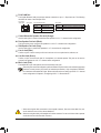
Example: Installing and Removing a PCI Express Graphics Card:
• Installing a Graphics Card:
Gently push down on the top edge of the card until it
is fully inserted into the PCI Express slot. Make sure
the card is securely seated in the slot and does not
rock.
• Removing the Card:
Gently push back on the lever on the slot and then lift the card straight out from the
slot.
PCI Slot
PCI Express x1 Slot
PCI Express x16 Slot

- 19 -
Hardware Installation
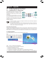
1-6 SetupoftheAMDDualGraphicsConguration
Combining the onboard GPU with a discrete graphics card, AMD's Dual Graphics technology can provide
signicantlyadvanceddisplayperformanceforAMDplatform.Readthefollowinginstructionsonconguringa
Dual Graphics system.
A. System Requirements
- AMD A series processor
- Windows8/7operatingsystem
- AnAMDDualGraphicstechnology-supportedmotherboard(withtheBIOSupdatedtothelatestversion)
andcorrectdriver(makesuretheonboardgraphicsdriverversionisRev.8.982orabove)
- An AMD Radeon
™
HD6000seriesgraphicscardthatsupportsAMDDualGraphicstechnology(formore
details,pleasevisitAMD'sofcialwebsite)andcorrectdriver
B.InstallingtheGraphicsCardsandConguringBIOSSetup
Step 1:
Observe the steps in "1-5 Installing an Expansion Card" and install an AMD Dual Graphics technology-supported
graphics card on the PCIEX16 slot. Plug the monitor cable into the graphics card and start up your computer.
Step 2:
Enter BIOS Setup to set the following items under the Peripherals\GFXConguration menu:
- Set Integrated Graphics to Force.
- Set UMA Frame Buffer Size to 512M or above.
Save the settings and exit BIOS Setup. Restart your computer.
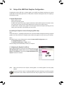
C.ConguringtheGraphicsCardDriver
After installing the graphics card driver in the operating system, go to the
AMD VISION Engine Control Center. Browse to Performance\AMD
Radeon
™
Dual Graphics and ensure the Enable AMD Radeon Dual
Graphics check box is selected.
(Note) MakesurethedriversfortheChipset,onboardgraphics,andexternalgraphicscardareproperly
installed.
Procedure and driver screen for enabling the AMD Dual Graphics technology may differ by graphics
card and driver version. Refer to the manual that came with your graphics card for more information.

- 20 -
Hardware Installation
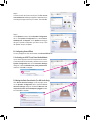
1-7 Setting up AMD CrossFire
™
Conguration
A. System Requirements
- Windows8,Windows7orWindowsXPoperatingsystem
- A CrossFire-supported motherboard with two PCI Express x16 slots and correct driver
- Two CrossFire-ready graphics cards of identical brand and chip and correct driver
- CrossFire
(Note)
bridge connector
- Apowersupplywithsufcientpowerisrecommended(Refertothemanualofyourgraphicscardsforthe
powerrequirement)
B. Connecting the Graphics Cards
Step 1:
Observe the steps in "1-5 Installing an Expansion Card" and install CrossFire graphics cards on the PCIEX16
and PCIEX8 slots.
Step 2:
Insert the CrossFire
(Note)
bridge connectors in the CrossFire gold edge connectors on top of the cards.
Step 3:
Plug the display cable into the graphics card on the PCIEX16 slot.
C.ConguringtheGraphicsCardDriver
To Enable CrossFire Function
After installing the graphics card driver in the operating system, go to
the AMD VISION Engine Control Center. Browse to Performance\
AMD CrossFire
™
CongurationandensuretheEnable CrossFire
™
check box is selected. and click Apply.
(Note) Thebridgeconnector(s)maybeneededornotdependingonyourgraphicscards.
Procedure and driver screen for enabling CrossFire technology may differ by graphics cards. Refer to the
manual that came with your graphics cards for more information about enabling CrossFire technology.
Page is loading ...
Page is loading ...
Page is loading ...
Page is loading ...
Page is loading ...
Page is loading ...
Page is loading ...
Page is loading ...
Page is loading ...
Page is loading ...
Page is loading ...
Page is loading ...
Page is loading ...
Page is loading ...
Page is loading ...
Page is loading ...
Page is loading ...
Page is loading ...
Page is loading ...
Page is loading ...
Page is loading ...
Page is loading ...
Page is loading ...
Page is loading ...
Page is loading ...
Page is loading ...
Page is loading ...
Page is loading ...
Page is loading ...
Page is loading ...
Page is loading ...
Page is loading ...
Page is loading ...
Page is loading ...
Page is loading ...
Page is loading ...
Page is loading ...
Page is loading ...
Page is loading ...
Page is loading ...
Page is loading ...
Page is loading ...
Page is loading ...
Page is loading ...
Page is loading ...
Page is loading ...
Page is loading ...
Page is loading ...
Page is loading ...
Page is loading ...
Page is loading ...
Page is loading ...
Page is loading ...
Page is loading ...
Page is loading ...
Page is loading ...
Page is loading ...
Page is loading ...
Page is loading ...
Page is loading ...
Page is loading ...
Page is loading ...
Page is loading ...
Page is loading ...
Page is loading ...
Page is loading ...
Page is loading ...
Page is loading ...
Page is loading ...
Page is loading ...
Page is loading ...
Page is loading ...
Page is loading ...
Page is loading ...
Page is loading ...
Page is loading ...
-
 1
1
-
 2
2
-
 3
3
-
 4
4
-
 5
5
-
 6
6
-
 7
7
-
 8
8
-
 9
9
-
 10
10
-
 11
11
-
 12
12
-
 13
13
-
 14
14
-
 15
15
-
 16
16
-
 17
17
-
 18
18
-
 19
19
-
 20
20
-
 21
21
-
 22
22
-
 23
23
-
 24
24
-
 25
25
-
 26
26
-
 27
27
-
 28
28
-
 29
29
-
 30
30
-
 31
31
-
 32
32
-
 33
33
-
 34
34
-
 35
35
-
 36
36
-
 37
37
-
 38
38
-
 39
39
-
 40
40
-
 41
41
-
 42
42
-
 43
43
-
 44
44
-
 45
45
-
 46
46
-
 47
47
-
 48
48
-
 49
49
-
 50
50
-
 51
51
-
 52
52
-
 53
53
-
 54
54
-
 55
55
-
 56
56
-
 57
57
-
 58
58
-
 59
59
-
 60
60
-
 61
61
-
 62
62
-
 63
63
-
 64
64
-
 65
65
-
 66
66
-
 67
67
-
 68
68
-
 69
69
-
 70
70
-
 71
71
-
 72
72
-
 73
73
-
 74
74
-
 75
75
-
 76
76
-
 77
77
-
 78
78
-
 79
79
-
 80
80
-
 81
81
-
 82
82
-
 83
83
-
 84
84
-
 85
85
-
 86
86
-
 87
87
-
 88
88
-
 89
89
-
 90
90
-
 91
91
-
 92
92
-
 93
93
-
 94
94
-
 95
95
-
 96
96


Gigabyte GA-F2A88X-UP4 (rev. 3.0) User manual
- Category
- Motherboards
- Type
- User manual
Ask a question and I''ll find the answer in the document
Finding information in a document is now easier with AI
Related papers
-
Gigabyte GA-F2A88XN-WIFI Owner's manual
-
Gigabyte GA-F2A85X-UP4 Owner's manual
-
-
Gigabyte GA-F2A88XM-D3H Owner's manual
-
-
Gigabyte GA-F2A55M-DS2GA-F2A55M-HD2GA-F2A75-D3HGA-F2A75M-D3HGA-F2A85X-D3HGA-F2A85X-UP4GA-F2A85XM-D3H Owner's manual
-
Gigabyte GA-Z77P-D3 User manual
-
-
-
Gigabyte GA-F2A68HM-DS2 Owner's manual
Other documents
-
ECS A78F2P-M2 User manual
-
 PowerColor AXR7 250 2GBK3-HV2E/OC Datasheet
-
Sapphire 11229-07-20G User guide
-
MAIWO KC014 User manual
-
 AV Access U3SW24 User manual
-
MSI A88X-G43 Series Owner's manual
-
MSI A88X-G41 PC MATE User manual
-
MSI A58-G41 PC Mate User manual
-
Gateway FX8010 Setup Manual
-
PNY 91007240 User manual

