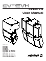
Electro-Voice EVF-1122S/96-FG User manual
- Category
- Loudspeakers
- Type
- User manual

Electro-Voice EVF/EVH User Manual
EVF/EVH
User Manual
EVF-1121S
EVF-1151S
EVF-1181S
EVF-2121S
EVF-2151D
EVF-1122S (All Patterns)
EVF-1122D (All Patterns)
EVF-1152S (All Patterns)
EVF-1152D (All Patterns)
EVH-1152S (All Patterns)
EVH-1152D (All Patterns)

Electro-Voice EVF/EVH User Manual
Table of Contents
Rigging-Safety Warning ...........................................................................................................................................................................................3
1.0 Introduction ........................................................................................................................................................................................................ 4
1.1 Finishes and Colors Available ......................................................................................................................................................... 9
1.2 EVF Front-Loaded Series ................................................................................................................................................................9
1.3 EVH Horn-Loaded Series ................................................................................................................................................................ 9
1.4 Accessories for EVF and EVH Systems ..................................................................................................................................... 10
2.0 Tool List ......................................................................................................................................................................................................10
3.0 Designing an EVF/EVH Cluster ................................................................................................................................................................. 11
3.1 General Aiming and Placement Guidelines .............................................................................................................................. 11
3.2 Choosing between the EVF Full-Range and EVH Full-Range Systems ............................................................................ 11
3.21 Directivity Break Frequency Defined ........................................................................................................................ 11
3.3 More on Coverage Patterns, Multiple Coverage Patterns, the Need for Clusters of
Loudspeakers and How Far a Single Cluster Can “Reach” into a Venue ......................................................................... 12
3.31 Basic Clustering Guidelines ...................................................................................................................................... 12
3.4 Coverage-Uniformity Target ......................................................................................................................................................... 13
3.5 Multiple-Source Interference in Clusters .................................................................................................................................. 14
3.51 Reducing Multiple-Source Interference .................................................................................................................. 16
4.0 Preparing EVF and EVH Systems for Installation ................................................................................................................................... 19
4.1 Recommended Preflight Procedures ......................................................................................................................................... 19
4.2 Passive/Biamp Crossover Configuration .................................................................................................................................. 19
4.3 Rotation of High-Frequency Waveguides (EVF Systems) .................................................................................................... 20
4.4 Rotation of High-Frequency Waveguides and Mid-Frequency Waveguide
Contours (EVH Systems) .............................................................................................................................................................. 20
4.5 Digital Signal Processing .............................................................................................................................................................. 21
4.51 Full-Range Systems in Passive Mode ..................................................................................................................... 21
4.52 Using the EVF-1121S and EVF-1151S Low-Frequency Systems in Full-Range
Clusters that Operate on a Single Power-Amplifier Channel ............................................................................ 22
4.53 DSP (Digital Signal Processor) Loudspeaker Presets for Biamp Operation ................................................. 22
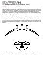
5.0 EVF and EVH Rigging System .................................................................................................................................................................... 23
5.1 Introduction ...................................................................................................................................................................................... 23
5.11 The Flying EV-Innovation (EV-I) Loudspeaker System ........................................................................................ 23
5.12 Important Details that Apply to the VRK and HRK Rigging Kits ....................................................................... 26
5.2 EV-I Rigging Primer ........................................................................................................................................................................ 26
5.21 Anatomy of an EVF or EVH Flying System Using M10 Eyebolts ....................................................................... 27
5.211 Eyebolt Application Warnings ................................................................................................................. 27
5.212 Eyebolt Installation ..................................................................................................................................... 28
5.213 All-Eyebolt Clusters ................................................................................................................................... 29
5.22 VRK Kits and Vertically Rigged Clusters ................................................................................................................ 31
5.23 HRK Kits and Horizontally Rigged Clusters .......................................................................................................... 32
5.24 Assembly Instructions for VRK and HRK Kits ....................................................................................................... 35
6.0 Rigging-Strength Ratings and Safety Factors .........................................................................................................................................37
6.1 Working Load Limit and Safety-Factor Definitions ..................................................................................................................37
6.2 Structural-Rating Overview .......................................................................................................................................................... 38
6.3 All-Eyebolt Structural Ratings ...................................................................................................................................................... 39
6.31 Working Load Limits for Eyebolts ............................................................................................................................. 40
6.32 Suspension-Line Angles ............................................................................................................................................. 41
6.33 Left-to-Right All-Eyebolt Cluster Angles ................................................................................................................ 41
6.4 VRK Rigging Structural Ratings for Vertical Clusters ............................................................................................................ 42
6.41 Working Load Limits for Eyebolts used with VRK Vertical Rigging Kits .......................................................... 44
6.42 Left-to-Right Vertical Cluster Angles ....................................................................................................................... 45
2

Electro-Voice EVF/EVH User Manual
Rigging-Safety Warning
3
This document details general rigging practices appropriate to the entertainment industry, as they would apply to the rigging
of Electro-Voice EVF and EVH loudspeaker systems. It is intended to familiarize the reader with standard rigging hardware and
techniques for suspending EVF and EVH loudspeaker systems overhead. Only persons with the knowledge of proper hardware
and safe rigging techniques should attempt to suspend any sound systems overhead. Prior to suspending any Electro-Voice
EVF and EVH loudspeaker systems overhead, it is essential that the user be familiar with the strength ratings, rigging tech-
niques and special safety considerations outlined in this manual. The rigging techniques and practices recommended in this
manual are, of necessity, in general terms to accommodate the many variations in loudspeaker clusters and rigging configura-
tions. As such, the user is expressly responsible for the safety of all specific EVF and EVH loudspeaker cluster
designs and rigging configurations as implemented in practice.
All the general rigging material contained in this manual is based on the best available engineering information concerning
materials and practices, as commonly recognized in the United States, and is believed to be accurate at the time of original
printing. As such, the information may not be directly applicable in other countries. Furthermore, the regulations and require-
ments governing rigging hardware and practices may be superseded by local regulations. It is the responsibility of the user to
ensure that any Electro-Voice loudspeaker system is suspended overhead in accordance with all current federal, state and local
regulations.
All specific material concerning the strength ratings, rigging techniques and safety considerations for the EVF and EVH loud-
speaker systems is based on the best available engineering information concerning the use and limitations of the products.
Electro-Voice continually engages in testing, research and development of its loudspeaker products. As a result, the specifi-
cations are subject to change without notice. It is the responsibility of the user to ensure that any Electro-Voice loudspeaker
system is suspended overhead in accordance with the strength ratings, rigging techniques and safety considerations given in
this document and any manual update notices. All non-Electro-Voice associated hardware items necessary to rig a complete
EVF and EVH loudspeaker cluster (chain hoists, building or tower supports and miscellaneous mechanical components) are the
responsibility of others.
Electro-Voice
June 2010
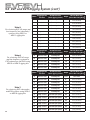
Table of Contents (cont’)
6.5 HRK Rigging Structural Ratings for Horizontal Clusters ...................................................................................................... 46
6.51 Using Tie Plates as Main Load-Bearing Suspension ............................................................................................47
6.52 Suspension-Line Angles for HRK Kits .................................................................................................................... 48
6.53 Symmetry for Horizontal Clusters using HRK Kits ............................................................................................... 49
6.54 Inner Connection Points ............................................................................................................................................. 50
6.55 Left-to-Right Horizontal Cluster Angles .................................................................................................................. 50
6.6 Ratings for Outdoor Applications with Wind Loading ........................................................................................................... 51
6.7 Electro-Voice Structural-Analysis Procedures ......................................................................................................................... 51
7.0 Rigging Inspection and Precautions ........................................................................................................................................................... 52
8.0 References ..................................................................................................................................................................................................... 53
8.1 Rigging (Printed) ............................................................................................................................................................................. 53
8.2 Mechanical Engineering (Printed) ............................................................................................................................................... 53
8.3 Rigging (Websites) ........................................................................................................................................................................ 53
Notes ......................................................................................................................................................................................................................... 54

Electro-Voice EVF/EVH User Manual
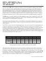
1.0 Introduction
The Electro-Voice EVF series is a group of compact two-way front-loaded full-range systems, available
with 12- or 15-inch woofers, augmented by low-frequency and subwoofer systems. EVF full-range sys-
tems are available in two versions. The “S” versions employ 400-watt SMX low-frequency transducers
and the ND2B medium-format, 1.4-inch exit/2-inch diaphragm compression driver. The “D” versions em-
ploy 500-watt DVX-A low-frequency transducers and the DH7N large-format, 1.4-inch exit/3-inch dia-
phragm compression driver. Both compression drivers have neodymium magnetic structures. In general,
the premium components in the “D” versions provide lower distortion and reduced power compression.
The EVH series is a group of larger two-way horn-loaded full-range systems. Both the “S” and “D” EVH
versions use SMX low-frequency transducers. The “D” versions substitute the DH7N large-format com-
pression driver for the ND2B medium-format driver.
All full-range systems utilize high-order crossover networks that seamlessly integrate the low-frequency
transducers with the high-frequency compression drivers, providing very low distortion and excellent fre-
quency response.
The EVF/EVH systems have many threaded rigging points that can be used with the supplied eyebolt kits
or optional suspension kits to easily create a number of horizontal or vertical cluster configurations. All
enclosures in their normal orientations (long axis vertical) share the same height, just over 30 inches (762
mm), promoting attractive clusters. Six coverage patterns, all rotatable, are available in each family, as
shown in Table 1a. The EVF-1121S and EVF-1151S low-frequency systems have integral low-pass filters
that allow paralleling them with up to two full-range systems, offering a cost-effective way to augment the
low-frequency output of EVF full-range systems.
4
The model number scheme denotes the number of woofers, the diameter of the woofers, the number of
band passes in the system, the woofer series used and, following a forward slash, the coverage pattern.
An example is the EVF-1122S/96, which has a single SMX series 12-inch woofer in a two-way configura-
tion and a 90° x 60° pattern. Another example is the EVF-1181S subwoofer, which has a single EVS-18S
18-inch woofer in a “one way” configuration and without a specific coverage pattern (essentially omnidi-
rectional in the very-low-frequency range in which it is usually operated).
Table 1a:
Coverage patterns available in the EVF and EVH series (all rotatable)
Horn Pattern: 40° x 30° 60° x 40° 60° x 60° 90° x 40° 90° x 60° 90° x 90° 120° x 60°
EVF 12-inch
• • • • • •
EVF 15-inch
• • • • • •
EVH
• • • • • •

Electro-Voice EVF/EVH User Manual 5
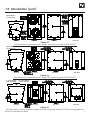
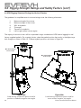
Typical EVF and EVH systems are shown in Figure 1, with key dimensions, suspension points, weights
and centers-of-gravity. Engineering data sheets for each model, containing full specifications and dimen-
sional drawings, are shipped with each loudspeaker and are downloadable from the Electro-Voice Web
site (www.electrovoice.com).
Table 1b:
Model number scheme, showing the meaning of each individual model number
Model Name
(As Shown)
EVF-1122S/96 (example)
Model Name
(Separated)
EVF - 1 12 2 S / 96
Description
Loudspeaker
Family/Series
(EVF Series)
Number of
Woofers
(1 Woofer)
Woofer
Diameter
(12-inch)
Number of
Band Passes
(Two-Way)
Woofer
Series Used
(SMX Series)
Coverage
Pattern
(90° x 60°)
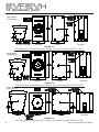
1.0 Introduction (cont’)
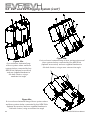
Figure 1a:
Key dimensions, suspension points, weight, and center-of-gravity for EVF-1122 (all coverage patterns)
Figure 1b:
Key dimensions, suspension points, weight, and center-of-gravity for EVF-1152 (all coverage patterns)
Front ViewEnd View
Side View
Rear View
“S” System Weight -
60.0 lb (27.2 kg)
Front ViewEnd View
Side View
Rear View
“S” System Weight -
70.1 lb (31.8 kg)
“D” System Weight -
65.5 lb (29.7 kg)
“D” System Weight -
75.7 lb (34.4 kg)

Electro-Voice EVF/EVH User Manual
1.0 Introduction (cont’)
Figure 1c:
Key dimensions, suspension points, weight, and center-of-gravity for EVF-1121S
Front ViewEnd View
Side View
Rear View
System Weight -
57.7 lb (26.2 kg)
Figure 1d:
Key dimensions, suspension points, weight, and center-of-gravity for EVF-1151S
Figure 1e:
Key dimensions, suspension points, weight, and center-of-gravity for EVF-1181S
System Weight -
62.6 lb (28.4 kg)
Front ViewEnd View
Side View
Rear View
System Weight -
101.2 lb (46.0 kg)
Front ViewEnd View
Side View
Rear View
6

Electro-Voice EVF/EVH User Manual
Figure 1f:
Key dimensions, suspension points, weight, and center-of-gravity for EVF-2121S
Figure 1g:
Key dimensions, suspension points, weight, and center-of-gravity for EVF-2151D
Figure 1h:
Key dimensions, suspension points, weight, and center-of-gravity for EVH-1152 (all coverage patterns)
System Weight -
82.4 lb (37.4 kg)
Front ViewEnd View
Side View
Rear View
System Weight -
117.0 lb (53.1 kg)
Front ViewEnd View
Side View
Rear View
“S” System Weight -
143.0 lb (64.9 kg)
Front ViewEnd View
Side View
Rear View
1.0 Introduction (cont’)
7
“D” System Weight -
145.5 lb (66.1 kg)

Electro-Voice EVF/EVH User Manual
1.0 Introduction (cont’)
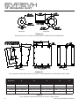
Figure 1h:
Key suspension point dimensions for EVF or EVH loudspeakers as indicated in table below
Figure 1g:
Key dimensions for washers and eyebolts included with each loudspeaker
Washer (x4)
Eyebolt (x4)
End View
Side View
Rear View
Table 2:
Key suspension point dimensions as shown in figure above
Dimension: A B C D E°
EVF 12-inch 4.176” [106.07mm] 14.301” [363.24mm] N/A 16.129” [409.67mm] 15°
EVF 15-inch 4.176” [106.07mm] 14.301” [363.24mm] N/A 18.353” [466.16mm] 15°
EVF Subs 3.957” [100.50mm] 13.889” [352.77mm] 23.857” [605.97mm] 28.255” [717.68mm] 10°
EVH 3.957” [100.50mm] 13.889” [352.77mm] 23.857” [605.97mm] 26.409” [670.79mm] 10°
8

Electro-Voice EVF/EVH User Manual
1.0 Introduction (cont’)
1.1 Finishes and Colors Available
The standard EVF/EVH indoor versions are finished in tough EVCoat™. In addition, all models are available
in two levels of weather resistance, indicated by letters following the coverage-pattern numbers. The FG
versions, e.g., EVF-1152S/64-FGB, are designed for full weather exposure and feature a fiberglass-fin-
ished enclosure, stainless-steel hydrophobic grille and the CDG dual-gland-nut input-panel cover. The PI
versions, e.g., EVF-1152S/64-PIW, are rated for indirect outdoor exposure only in protected areas, such
as under a roof overhang, and feature a stainless-steel hydrophobic grille and CDG dual-gland-nut input-
panel cover on an enclosure finished in standard EVCoat. External fasteners on all systems are stainless
steel.
All EVF and EVH systems are available in black or white. Black is indicated by BLK or B at the very end of
the complete model number and white is indicated by WHT or W at the very end of the complete model
number, e.g., EVF-1152/94-BLK and EVF-1152S/94-PIW.
1.2 EVF Front-Loaded Series
Note that engineering data sheets with complete specifications are packed with each system and down-
loadable at www.electrovoice.com.
EVF-1122S/64, EVF-1122S/66, EVF-1122S/94, EVF-1122S/96, EVF-1122S/99, EVF-1122S/126,
EVF-1122D/64, EVF-1122D/66, EVF-1122D/94, EVF-1122D/96, EVF-1122D/99, EVF-1122D/126:
two-way 12-inch full-range systems with six different rotatable waveguides ranging from 60° x 40° to
120° by 60°, as detailed in Table 1.
EVF-1152S/43, EVF-1152S/64, EVF-1152S/66, EVF-1152S/94, EVF-1152S/96, EVF-1152S/99,
EVF-1152D/43, EVF-1152D/64, EVF-1152D/66, EVF-1152D/94, EVF-1152D/96, EVF-1152D/99:
two-way 15-inch full-range systems with six different rotatable waveguides ranging from 40° x 30° to
90° by 90°, as detailed in Table 1.
EVF-1121S: 12-inch low-frequency system.
EVF-1151S: 15-inch low-frequency system.
EVF-1181S: 18-inch subwoofer system.
EVF-2121S: Dual 12-inch low-frequency system.
EVF-2151D: Dual 15-inch subwoofer system.
1.3 EVH Horn-Loaded Series
Note that engineering data sheets with complete specifications are packed with each system and down-
loadable at www.electrovoice.com.
EVH-1152S/43, EVH-1152S/64, EVH-1152S/66, EVH-1152S/94, EVH-1152S/96, EVH-1152S/99,
EVH-1152D/43, EVH-1152D/64, EVH-1152D/66, EVH-1152D/94, EVH-1152D/96, EVH-1152D/99:
two-way 15-inch full-range systems with six different rotatable high-frequency waveguides ranging from
40° x 30° to 90° x 90° and mid-frequency waveguide contours, as detailed in Table 1.
9

Electro-Voice EVF/EVH User Manual
2.0 Tool List
Listed below are the tools required to prepare EVF and EVH systems for installation:
1. 3/16-inch flat-blade screwdriver (for attaching signal wires to input-panel connectors).
2. Phillips #2 screwdriver (for grille removal to rotate waveguides, removal of high-frequency
waveguides for rotation, and removal of input panel to install the optional TK-150
70.7/100-volt transformer).
3. 4-mm Allen (hex) wrench (for removal and reorientation of the EVH hard foam
mid-frequency waveguide contours to rotate the mid-frequency coverage pattern).
4. 6-mm Allen (hex) wrench (for working with all rigging points).
1.0 Introduction (cont’)
1.4 Accessories for EVF and EVH Systems
Note that some accessories are supplied with certain system versions, as noted.
CDG: optional dual-gland-nut input-panel cover to protect the input connections from water. Note that
this cover is supplied with the weather-resistant versions.
CSG: optional single-gland-nut input-panel cover to protect the input connections from water.
CDNL4: optional input-panel cover equipped with dual Neutrik Speakon
®
NL4M connectors, providing a
quick-disconnect alternative to the standard Phoenix screw-terminal input connectors.
HRK and VRK: a series of horizontal (HRK) and vertical (VRK) rigging kits that accommodate a number
of horizontal and vertical system aiming angles. See section 5.0 EVF and EVH Rigging System for details.
TK-150: optional 70.7/100-volt transformer kit mounts on the inside of the EVF and EVH input panels,
offering 37.5, 75 and 150 watts at 70.7 volts and 75 and 150 watts at 100 volts. Installation instructions
come with the TK-150.
EVF-UB: optional U-bracket kit for mounting single EVF full-range and low-frequency (not subwoofer)
systems to a wall or ceiling. Installation instructions come with the EVF-UB.
EVI-M10K: optional eyebolt kit, consisting of four M10 shoulder eyebolts and four fender washers, used
when additional eyebolts are needed to suspend loudspeakers. See section 6.3 for details. One EVI-
M10K eyebolt kit is supplied with each loudspeaker system.
EVI-AC: optional access card which allows diagnostic access to the transducers and protection circuitry
inside the enclosure. Use of this accessory does not require any disassembly or disconnections beyond
removal of the plug-in switch card.
10

Electro-Voice EVF/EVH User Manual
3.0 Designing an EVF/EVH Cluster
3.1 General Aiming and Placement Guidelines
Loudspeakers should be “pointed at the people” and away from reflective room surfaces. Since people
are excellent absorbers of sound and room surfaces are often not, this practice insures not only that the
audience will receive the high frequencies necessary for good voice intelligibility and musical clarity but
also that the reflective surfaces do not energize the room with intelligibility-robbing reverberation.
Loudspeakers for sound reinforcement are usually located high above a stage or platform and aimed
down and out into the audience. This minimizes the difference between the longest throws to the rear of
a venue and the shortest throws to the front rows, promoting coverage uniformity. Note that the typical
portable loudspeaker on a short, 6-foot stand cannot duplicate such uniformity since the distant seats are
so much farther away than the front rows. The direct sound from a loudspeaker drops 6 dB every time the
distance from it doubles, according to the formula:
Level loss (dB) = 20log
10
(closest distance/farthest distance).
See comments on the audibility of different dB differences in section 3.4 Coverage-Uniformity Target.
3.2 Choosing between the EVF Full-Range and the EVH Full-Range Systems
When the reverberation time of a room (formally called T60 and the time it takes sound, once the source
has stopped, to decay by 60 dB) exceeds 2-2.5 seconds at mid frequencies, the horn-loaded EVH series
should be used. The EVH’s low-frequency horn mouth is large enough to control the rated coverage pat-
tern down to 500 Hz, which promotes clarity by keeping more sound off of reflective surfaces than can the
smaller, 12-inch-square horns and direct-radiating woofers of the EVF series. This concept is explored in
more detail below.
3.21 Directivity Break Frequency Defined
Below a certain frequency, the mouth size of a waveguide is no longer large enough to maintain the nomi-
nal coverage angle and the coverage angle gets wider and wider as frequency is decreased. The fre-
quency at which this occurs is called the “directivity break frequency” (f
b
) and is inversely proportional to
the size of the waveguide mouth and the nominal coverage angle of the waveguide. The directivity break
frequency can be approximated by the following formula:
f
b
(Hz) = 1,000,000/[angle (degrees) x dimension (inches)].
11

Electro-Voice EVF/EVH User Manual
3.0 Designing an EVF/EVH Cluster (cont’)
3.3 More on Coverage Patterns, Multiple Coverage Patterns, the Need for Clusters of Loud-
speakers and How Far a Single Cluster Can “Reach” into a Venue
The coverage patterns or angles mentioned previously are defined where loudspeaker output is 6 dB
down from maximum, usually on-axis level. In order to help cover only the absorptive audience with sound,
given different trim heights and the wide variety of venue shapes, the EVF and EVH series are offered in
the many coverage patterns listed in Table 1 (above). Even with this wide choice, it is relatively unlikely that
a single loudspeaker will cover the audience uniformly. Therefore, two or more loudspeakers are often as-
sembled into clusters and aimed in different directions in order to reach the entire audience.
3.31 Basic Clustering Guidelines
The aiming angles of systems in a cluster are related not only to room geometry but also to the particular
coverage patterns selected. A rough design can be based on the plan and elevation views of a room, rep-
resenting the loudspeakers by the angles of their horizontal and vertical coverage patterns, e.g., 60° x 40°.
A wide or “short throw” coverage pattern, such as 120° x 60°, is good for aiming down into the front rows
of a rectangular venue to reach all of the seats left to right. Narrower patterns, such as 60° x 40° and
40° x 30°, are appropriate as “long throw” devices that send sound to the rear of the audience without
also “blasting out” the front rows.
Sophisticated software is also available, which allows the designer to build a room model and place and
aim loudspeakers within it, assessing the uniformity of coverage. An example is EASE 4.2 (Enhanced
Acoustic Simulator for Engineers), developed by Acoustic Design Ahnert (www.ada-acousticdesign.
de). EASE is available from the Bosch Communications Systems/Electro-Voice technical support group;
specific contact information can be found at www.electrovoice.com. EASE loudspeaker data for EVF and
EVH systems may be downloaded at www.electrovoice.com.
A common practice is to widen the horizontal coverage of a single loudspeaker by placing two systems
side by side and aiming them in such a way that their horizontal patterns do not overlap. Individually, each
system will be 6 dB down at the overlap point. Together at the overlap point, they will sum coherently to
the 0-dB on-axis level. A specific example is two 60° horizontal systems clustered together with their axes
placed 60° apart.
If these two systems are “underlapped,” with, say, their axes 75° apart, the overall coverage angle will be
wider but the level near the array axis will drop. If the two systems are overlapped to any great degree,
e.g., their axes only 45° apart, the overall coverage angle will be reduced and the interference discussed
in section 3.5 Multiple-Source Interference in Clusters will be worsened.
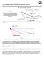
The degree to which long-throw devices can extend the region of uniform coverage is limited. A single
loudspeaker will typically “reach” to the rear a distance that is about twice that of the distance to the clos-
est front row. See Figure 2.
12

Electro-Voice EVF/EVH User Manual 13
Figure 2:
Typical “reach” of a single loudspeaker
into a venue (D
I
) in order to maintain
the desired ±3 dB coverage is about
two times the distance to the closest
seats (D
S
)
3.0 Designing an EVF/EVH Cluster (cont’)
Adding a long-throw device will typically extend this reach to about three times the closest distance. See
Figure 3.
Figure 3:
Adding a long-throw device extends the reach to about three times the distance to the closest seat
For reaches beyond this, loudspeakers can be suspended over the audience, with their signal delayed
with respect to the front or source loudspeakers so that the sound image will appear to come from the
front of the room. The details of these design tips are beyond the scope of this manual and should be left
to experienced design personnel.
3.4 Coverage-Uniformity Target
A good uniformity target is ±3 dB throughout the audience area, particularly in the 2,000- and 4,000-Hz
octave bands, the bands most important for intelligibility. Such coverage should also be achieved in the
8,000-Hz band, important for “sparkle.” As a reference, a 1-dB level difference is nearly imperceptible, a
3-dB difference is noticeable but not a large change, a 6-dB change is clearly noticeable and a 10-dB
change is twice or half as loud. The ±3-dB uniformity target is related to these perceptual differences.

Electro-Voice EVF/EVH User Manual14
3.5 Multiple-Source Interference in Clusters
Whenever two or more sources serve a single venue, some seats will receive strong signals from multiple
sources. Consider two EVF-1122S/64 60° x 40° systems clustered side by side with their axes 60° apart
to form a 120° x 40° cluster. If these systems maintained their rated coverage patterns into the low-
frequency range, there would be essentially no interference. But the 12-inch-square waveguides used in
the EVF series will begin to “balloon out” at about 2 kHz and below, an effect discussed in Section 3.21
Directivity Break Frequency Defined, above.
On the axis of the cluster, the output of both systems sums perfectly, since the listener is equidistant from
each system and the output of both reaches the listener at the same time. This is the axis-of-cluster line
shown in Figure 4. If the listener moves to the left (as viewed in the figure), the left loudspeaker will be
closer and the sound will arrive sooner. At some angle and at some frequency, the time difference will be
equivalent to reversing the polarity of one signal, causing a complete cancellation of cluster output at that
frequency.
Figure 4:
The two loudspeaker sources sum perfectly only on the axis of the cluster (as shown);
to the left and right of this axis, distance differences produce arrival-time differences
that cause cancellation of some frequencies (see text for more details)
3.0 Designing an EVF/EVH Cluster (cont’)

Electro-Voice EVF/EVH User Manual 15
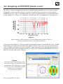
Figure 5:
Typical response off the array axis of the two loudspeakers shown in Figure 4,
showing cancellations due to arrival-time differences
This effect is shown in the frequency-response of Figure 5. Given the dimensions of the typical compact
loudspeaker systems and when they are clustered in close proximity to one another, the first several in-
terference nulls occur right in the middle of the vocal range. A frequency response with these ever-more-
closely spaced nulls is known as a “comb filter” response, after the visual appearance of the response.
3.0 Designing an EVF/EVH Cluster (cont’)
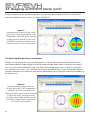
If one of the null frequencies is chosen and the horizontal polar response is measured, the result is shaped
like the blue polar response in the center lower graph of Figure 6. In this view, the cluster axis points up
(+X). Full output is achieved on this axis, since both signals arrive at the same time. But there are off-axis
problems. While the overall coverage of the cluster is about 120° (6 dB down), two deep nulls occur at
about 20° on either side of the cluster axis.
Figure 6:
Horizontal polar response (blue center
plot) of two closely clustered 60° x 40°
loudspeakers aimed 60° apart, showing
the off-axis nulls at 1,250 Hz caused by
multiple-source interference
(see text for more details)
NORMALIZED

Electro-Voice EVF/EVH User Manual16
At higher frequencies, the interference patterns become more densely packed, which essentially elimi-
nates their audibility. Figure 7 shows this effect at 8,000 Hz.
3.51 Reducing Multiple-Source Interference
Multiple-source interference cannot be eliminated but it can be substantially reduced. Systems which
have radiating devices large enough to hold their rated coverage angles down to relatively low frequen-
cies, such as the horn-loaded EVH series that hold their coverage angles down to 500 Hz, will exhibit
less interference in clusters. Also, doubling the distance between the two systems of Figure 8 produces
multiple interference nulls which are more densely packed than those of Figure 6, reducing the audibility of
the interference.
Figure 7:
Horizontal polar response (blue center
plot) of two closely clustered 60° x 40°
loudspeakers aimed 60° apart, showing
multiple, densely packed off-axis nulls
at 8,000 Hz caused by multiple-source
interference (see text for more details)
3.0 Designing an EVF/EVH Cluster (cont’)
Figure 8:
Horizontal polar response (blue cen-
ter plot) of two 60° x 40° loudspeakers
aimed 60° apart but with double the
distance between grille centers compared
to Figures 6 and 7, showing the more
densely packed 1,250-Hz off-axis nulls
caused by multiple-source interference
(see text for more details)

Electro-Voice EVF/EVH User Manual 17
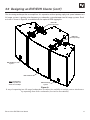
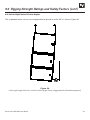
One clustering technique that accomplishes this separation without putting a physical space between two
full-range systems is putting a low-frequency or subwoofer system between two full-range systems. Such
a cluster is shown in Figure 9, assembled with the optional HRK rigging kits.
Figure 9:
A way of separating two full-range loudspeakers to reduce the audibility of multiple-source interference
by separating them with a subwoofer (see text for more details)
3.0 Designing an EVF/EVH Cluster (cont’)
Note: Loudspeakers
are non-specific and
shown as an example.
EVF Full-Range
System
EVF Subwoofer
EVF Full-Range
System
HRK-2 Kit
(Sold Separately)
HRK-2 Kit
(Sold Separately)

Electro-Voice EVF/EVH User Manual18
Finally, another way to reduce interference is to apply signal delay of up to 8 milliseconds to one of the
two systems. This requires a separate DSP (digital signal processor) drive to the delayed system. Figure
10 shows the dramatic smoothing achieved at 1,250 Hz. Note that the systems are still close together as
in Figure 6.
Figure 10:
Horizontal polar response (blue center plot) of two closely clustered 60° x 40° loudspeakers aimed 60°
apart, showing the smoothing of multiple-source interference caused by a 3-ms delay to one loudspeaker
3.0 Designing an EVF/EVH Cluster (cont’)
In clusters with more than two systems, adjacent boxes are usually delayed. While the effect can be
predicted with appropriate software (such as EASE 4.2), the actual delays are typically established in the
field during system setup and commissioning, by ear and measurements.

Electro-Voice EVF/EVH User Manual 19
4.0 Preparing EVF and EVH Systems for Installation
4.1 Recommended Preflight Procedures
For any installed sound system, certain checks made at the installer’s place of business can prevent ex-
pensive on-site delays. A short-list follows, and sets the stage for proper cluster performance:
1. Unpack all loudspeakers in the shop.
2. Check for proper model numbers.
3. Check the overall condition of the loudspeakers.
4. Check for continuity at the loudspeaker inputs.
It is a good idea, once on site and the loudspeakers are connected, to check again for continuity at the
power-amplifier end.
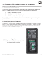
4.2 Passive/Biamp Crossover Configuration
All two-way EVF and EVH systems are shipped in the passive crossover mode. In the center of the input
panel is an external switch card that can change this configuration. See Figure 11. (Note that EVH input
panels, when the systems are in their normal, slanted-sides-vertical orientation, have their long axes ro-
tated 90° with respect to the EVF view of Figure 11.)
Figure 11:
EVF/EVH input panel as supplied, with the passive/biamp
switch card in its full-range passive position
(left position in picture as oriented)

Electro-Voice EVF/EVH User Manual20
4.0 Preparing EVF and EVH Systems for Installation (cont’)
To configure for biamp operation, remove the switch card by drawing it toward you using the central finger
hole. (The switch can also be removed with the end of a flat-blade screwdriver, by placing the blade end
in the switch hole and using the adjacent edge of the input panel as a fulcrum. To facilitate this operation,
there is a small recess in the edge of the input panel adjacent to the hole in switch card.) Reinsert the
switch card in its biamp-operation position (right position in the picture of Figure 11).
4.3 Rotation of High-Frequency Waveguides (EVF systems)
All high-frequency waveguides have their horizontal and vertical patterns molded in for easy identification
of orientation and are rotatable according to the following procedure:
1. With a #2 Phillips screwdriver, remove the four screws on each side of the enclosure and
pop the grille out.
2. With a #2 Phillips screwdriver, remove the 12 screws holding the compression-driver/
waveguide assembly.
3. Rotate the assembly 90° and reinstall.
4. Reinstall the grille.
4.4 Rotation of High-Frequency Waveguides and Mid-Frequency Waveguide Contours (EVH
systems)
1. With a #2 Phillips screwdriver, remove the four screws on each side of the enclosure and
pop the grille out.
2. With a #2 Phillips screwdriver, remove the four screws holding the compression-driver/HF
waveguide assembly.
3. Use a 6-mm Allen (hex) wrench to remove the two rails that hold the HF waveguide
assembly.
4. Use a 4-mm Allen (hex) wrench to remove the four screws holding the hard foam
mid-frequency waveguide contours in place on the left and right sides of the enclosure.
Figure 12 shows a contour in the process of being removed.
5. Rotate and reinstall the contours in the top and bottom of the enclosure.
6. Reinstall the two rails that hold the HF waveguide assembly.
7. Rotate and reinstall the compression-driver/HF waveguide assembly.
8. Reinstall the grille.
Page is loading ...
Page is loading ...
Page is loading ...
Page is loading ...
Page is loading ...
Page is loading ...
Page is loading ...
Page is loading ...
Page is loading ...
Page is loading ...
Page is loading ...
Page is loading ...
Page is loading ...
Page is loading ...
Page is loading ...
Page is loading ...
Page is loading ...
Page is loading ...
Page is loading ...
Page is loading ...
Page is loading ...
Page is loading ...
Page is loading ...
Page is loading ...
Page is loading ...
Page is loading ...
Page is loading ...
Page is loading ...
Page is loading ...
Page is loading ...
Page is loading ...
Page is loading ...
Page is loading ...
Page is loading ...
Page is loading ...
Page is loading ...
-
 1
1
-
 2
2
-
 3
3
-
 4
4
-
 5
5
-
 6
6
-
 7
7
-
 8
8
-
 9
9
-
 10
10
-
 11
11
-
 12
12
-
 13
13
-
 14
14
-
 15
15
-
 16
16
-
 17
17
-
 18
18
-
 19
19
-
 20
20
-
 21
21
-
 22
22
-
 23
23
-
 24
24
-
 25
25
-
 26
26
-
 27
27
-
 28
28
-
 29
29
-
 30
30
-
 31
31
-
 32
32
-
 33
33
-
 34
34
-
 35
35
-
 36
36
-
 37
37
-
 38
38
-
 39
39
-
 40
40
-
 41
41
-
 42
42
-
 43
43
-
 44
44
-
 45
45
-
 46
46
-
 47
47
-
 48
48
-
 49
49
-
 50
50
-
 51
51
-
 52
52
-
 53
53
-
 54
54
-
 55
55
-
 56
56


Electro-Voice EVF-1122S/96-FG User manual
- Category
- Loudspeakers
- Type
- User manual
Ask a question and I''ll find the answer in the document
Finding information in a document is now easier with AI
Related papers
-
Electro-Voice EVF & EVH User manual
-
-
-
Bosch ZX3-60PI-W User manual
-
-
Electro-Voice EBK1 User manual
-
-
-
-
Other documents
-
POLYWOOD NS48MA Operating instructions
-
Biamp WX-1200 Owner's manual
-
Quest Engineering UBHPI Rigging Installation Guide
-
Biamp Community R2-EN User manual
-
-
 EV Rider EVF-1152S/94 User manual
-
Bosch Appliances EVF-1122S/94-FG User manual
-
-
-
 Alvarez SA1530Z User manual

