BROAN ONE YEAR LIMITED WARRANTY
BROAN-NUTONE ONE YEAR LIMITED WARRANTY
Broan-Nutone warrants to the original consumer pur-
chaser of its products that such products will be free
from defects in materials or workmanship for a pe-
riod of one year from the date of original purchase.
THERE ARE NO OTHER WARRANTIES, EXPRESS
OR IMPLIED, INCLUDING, BUT NOT LIMITED TO,
IMPLIED WARRANTIES OF MERCHANTABILITY
OR FITNESS FOR A PARTICULAR PURPOSE.
During this one-year period, Broan-NuTone will, at
its option, repair or replace, without charge, any
product or part which is found to be defective under
normal use and service.
THIS WARRANTY DOES NOT EXTEND TO FLUO-
RESCENT LAMP STARTERS AND TUBES. This
warranty does not cover (a) normal maintenance and
service or (b) any products or parts which have been
subject to misuse, negligence, accident, improper
maintenance or repair (other than by Broan-NuTone),
faulty installation or installation contrary to recom-
mended installation instructions.
The duration of an implied warranty is limited to the
one-year period as specified for the express war-
ranty. Some states do not allow limitation on how
long an implied warranty lasts, so the above limita-
tion may not apply to you.
BROAN-NUTONE’S OBLIGATION TO REPAIR OR
REPLACE, AT BROAN-NUTONE’S OPTION, SHALL
BE THE PURCHASER’S SOLE AND EXCLUSIVE
REMEDY UNDER THIS WARRANTY. BROAN -
NUTONE SHALL NOT BE LIABLE FOR INCIDEN-
TAL, CONSEQUENTIAL OR SPECIAL DAMAGES
ARISING OUT OF OR IN CONNECTION WITH
PRODUCT USE OR PERFORMANCE. Some states
do not allow the exclusion or limitation of incidental
or consequential damages, so the above limitation
may not apply to you.
This warranty gives you specific legal rights, and you
may also have other rights, which vary from state to
state. This warranty supersedes all prior warran-
ties.
To qualify for warranty service, you must (a) notify
Broan-Nutone at the address stated below or tele-
phone: 1-800-637-1453, (b) give the model number
and part identification and (c) describe the nature of
any defect in the product or part. At the time of re-
questing warranty service, you must present evi-
dence of the original purchase date.
Broan-NuTone LLC
926 West State Street
Hartford, WI 53027
(1-800-637-1453)
GARANTIA BROAN-NUTONE LIMITADA POR
UN AÑO
Broan-Nutone garantiza al consumidor comprador
original de sus productos que dichos productos
carecerán de defectos en materiales o en mano de
obra por un período de un año a partir de la fecha
original de compra. NO EXISTEN OTRAS
GARANTIAS, EXPRESAS NI IMPLICITAS,
INCLUYENDO, PERO NO LIMITADAS A,
GARANTIAS IMPLICITAS DE COMERCIALIZACION
O APTITUD PARA UN PROPOSITO PARTICULAR.
Durante el período de un año, y a su propio criterio,
Broan-NuTone reparará o reemplazará, sin costo
alguno, cualquier producto o pieza que se encuentre
defectuosa bajo condiciones normales de servicio y
uso.
ESTA GARANTIA NO SE APLICA A TUBOS Y
ARRANCADORES DE LAMPARAS
FLUORESCENTES. Esta garantía no cubre (a)
mantenimiento y servicio normales ni (b) cualquier
producto o piezas que hayan sido utilizadas de forma
errónea, negligente, que hayan tenido un accidente,
o que hayan sido reparadas o mantenidas
incorrectamente (por otras compañías que no sean
Broan-NuTone), instalación defectuosa, o instalación
contraria a las instrucciones de instalación
recomendadas.
La duración de cualquier garantía implícita se limita
a un período de un año como se especifica en la
garantía expresa. Algunos estados no permiten
limitaciones en cuanto al tiempo de expiración de
una garantía implícita, por lo que la limitación antes
mencionada puede no corresponderle.
LA OBLIGACION DE BROAN-NUTONE DE
REPARAR O REEMPLAZAR, SIGUIENDO EL
CRITERIO DE BROAN-NUTONE, DEBERA SER EL
UNICO Y EXCLUSIVO RECURSO LEGAL DEL
COMPRADOR BAJO ESTA GARANTIA. BROAN -
NUTONENO SERA RESPONSABLE POR DAÑOS
ACCIDENTALES, CONSIGUIENTES, O POR
DAÑOS ESPECIALES RESULTANTES O EN
CONEXION CON EL USO O EL RENDIMIENTO DEL
PRODUCTO.
Algunos estados no permiten la exclusión o limitación
de daños accidentales o consiguientes, por lo que la
limitación antes mencionada puede no aplicarse a
usted.
Esta garantía le proporciona derechos legales
específicos, y usted puede también tener otros
derechos, los cuales varían de estado a estado. Esta
garantía reemplaza todas las garantías anteriores.
Para tener derecho al servicio de garantía, usted
debe (a) notificar a Broan-NuTone en la dirección
que se menciona abajo o al teléfono:1-800-637-1453
en los E.E. U.U., (b) dar el número del modelo y la
identificación de la pieza, y (c) describir la naturaleza
de cualquier defecto en el producto o pieza. En el
momento de solicitar servicio cubierto por la garantía,
usted debe presentar comprobación de la fecha origi-
nal de compra. Broan-NuTone LLC
926 West State Street
Hartford, WI 53027
(1-800-637-1453)
99042375M
Broan-NuTone LLC, 926 West State Street, Hartford, WI 53027 (1-800-637-1453)
658 ONLY
SOLO PAR EL
658
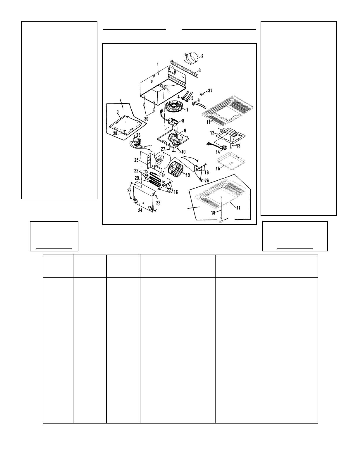
SERVICE PARTS
Models 656 & 658
PIEZAS DE SERVICIO
Modelos 656 y 658
KEY NO. MODEL 656 MODEL 658
NUMERO DE PART NO. PART NO. DESCRIPTION DESCRIPCION
CODIGO MODELO 656 MODELO 658
NO. PIEZ NO. PIEZ
1 97007383 97007383 Housing Carcasa
2 ----- 97014185 Damper Amortiguador
3 98003036 98003036 Mounting Bracket (4 Req.) Soporte de montaje (se necesitan 4)
4 99270479 ----- Receptacle, White Enchufe - Blanco
5 ----- 99270748 Receptacle, Black Enchufe - Negro
6 99270489 99270489 Receptacle, Red Enchufe - Rojo
7 ----- 99110446 Plastic Blower Wheel Disco de plástico del soplador
8 ----- 99080166 Fan Motor Motor del ventilador
9 97013628 97006987 Motor Plate / Partition Assembly Placa del motor/Conjunto del espaciador
10 ----- 99260428 Nut (4 Req.) Tuerca (se necesitan 4)
11 97013836 97013581 Grille Rejilla
12 97014211 ----- Light Reflector Reflector de luz
13 97005316 ----- Nut Tuerca
14 99770118 ----- Light Socket Casquillo de la lámpara
15 97013578 ----- Light Lens Lente de la luz
16 97005058 97005058 Bolt Assembly Conjunto de tornillos
17 ----- 99110748 Logo Button Botón con el logo
18 ----- 99150566 Grille Screw Tornillo de la parilla
19 99020290 99020290 Blower Wheel Disco del soplador
21 93260457 93260457 #10 - 32 Nut (7 Req.) Tuerca No. 10-32 (se necesitan 7)
22 99270107 99270107 Heater Hooks (5 Req.) Ganchos del calentador (se necesitan 5)
23 99150417 99150417 #8 x 1/4 Sheet Metal Screws (4 Req.)
Tornillos de lámina metálica No. 8 x 1/4 (se necesitan 4)
24 98003788 98003788 Heater Scroll Cover Cubierta de la espiral del calentador
25 97005006 97005006 Heater Scroll Housing Carcasa de la espiral del calentador
26 99080591 99080591 Heater Motor Motor del calentador
27 99170245 99170245 #8 x 3/8 Sheet Metal Screw Tornillo de lámina metálica No. 8 x 3/8
28 99160410 ----- Grille Stud Pasador de la rejilla
29 98004514 98004514 Heater Element Elemento calentador
30 99260566 99260566 Tinnerman Nut #10-32 (2 Req.) Tuerca Tinnerman No. 10 x 32 (se necesitan 2)
31 98000566 ----- Aluminum Receptacle Plug Enchufe de aluminio
Order service parts by Part No. - NOT by Key No.
Encargue piezas de servicio por No. Piez - NO por No. Codigo.
656 ONLY
SOLO PARA
EL 656
17
Replacement parts
can now be ordered
on our website.
Please visit us at
www.Broan.com
Las piezas de recambio se
pueden ahora pedir en
nuestro Web site. Visítenos
por favor en
www.Broan.com


