Page is loading ...

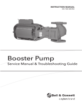
INSTRUCTION MANUAL
P2002884 Rev B
Series e-1500


Table of Contents
1 Introduction and Safety..............................................................................................................3
1.1 Introduction.......................................................................................................................... 3
1.2 Safety..................................................................................................................................... 3
1.2.1 Safety terminology and symbols.................................................................................3
1.2.2 Safety instruction decals.............................................................................................. 4
1.2.3 User safety......................................................................................................................5
1.2.4 Protecting the environment.........................................................................................6
2 Transportation and Storage...................................................................................................... 7
2.1 Examine the delivery........................................................................................................... 7
2.1.1 Examine the package................................................................................................... 7
2.1.2 Examine the unit............................................................................................................7
2.2 Pump lifting...........................................................................................................................7
2.3 Long-term storage............................................................................................................... 8
3 Product Description....................................................................................................................9
3.1 General description............................................................................................................. 9
3.2 Operational specifications.................................................................................................. 9
4 Installation................................................................................................................................. 11
4.1 Preinstallation.....................................................................................................................11
4.1.1 Pump mounting guidelines.......................................................................................11
4.1.2 Pump location guidelines..........................................................................................11
4.1.3 Piping checklist........................................................................................................... 12
4.2 Typical pump installation..................................................................................................12
5 Commissioning, Startup, Operation, and Shutdown.......................................................... 16
5.1 Preparation for startup...................................................................................................... 16
5.1.1 Check the rotation...................................................................................................... 16
5.2 Prime the pump................................................................................................................. 17
5.3 Start the pump....................................................................................................................17
5.4 Pump operation precautions............................................................................................17
5.5 Shut down the pump.........................................................................................................18
5.6 Note on the packed pump operation............................................................................. 18
5.7 Vibration..............................................................................................................................19
6 Maintenance..............................................................................................................................20
6.1 Lubrication..........................................................................................................................20
6.2 Disassembly........................................................................................................................20
6.2.1 Disassembly precautions...........................................................................................20
6.2.2 Drain the pump...........................................................................................................20
6.2.3 Remove the pump assembly.....................................................................................20
6.2.4 Remove the impeller.................................................................................................. 21
6.2.5 Remove the mechanical seal (e-1500–F)................................................................. 21
6.2.6 Remove the seal or packing rings (e-1500-S, e-1500-D, e-1500-PF)...................21
6.2.7 Remove the box type single mechanical seal (e-1500-S)...................................... 21
6.2.8 Impeller trimming guidelines....................................................................................21
6.3 Pre-assembly inspections................................................................................................. 22
6.3.1 Replacement guidelines............................................................................................ 22
6.3.2 Shaft inspection...........................................................................................................23
Table of Contents
Series e-1500 INSTRUCTION MANUAL 1

6.4 Reassembly.........................................................................................................................23
6.4.1 Assemble the standard mechanical seal (e-1500-F).............................................. 23
6.4.2 Assemble the single mechanical seal (e-1500-S)................................................... 24
6.4.3 Assemble the box type single mechanical seal (e-1500-S)................................... 24
6.4.4 Assemble the double mechanical seal (e-1500-D)................................................ 25
6.4.5 Assemble the packed stuffing box (e-1500-PF)......................................................26
6.4.6 Install the impeller...................................................................................................... 26
6.4.7 Reinstall the pump assembly.....................................................................................27
6.4.8 Screw torque values................................................................................................... 27
6.4.9 Dealer servicing ......................................................................................................... 27
7 Product warranty...................................................................................................................... 28
Table of Contents
2 Series e-1500 INSTRUCTION MANUAL

1 Introduction and Safety
1.1 Introduction
Purpose of this manual
The purpose of this manual is to provide necessary information for:
• Installation
• Operation
• Maintenance
CAUTION:
Read this manual carefully before installing and using the product. Improper use of the
product can cause personal injury and damage to property, and may void the warranty.
NOTICE:
Save this manual for future reference, and keep it readily available at the location of the
unit.
Requesting other information
Special versions can be supplied with supplementary instruction leaflets. See the sales
contract for any modifications or special version characteristics. For instructions,
situations, or events that are not considered in this manual or in the sales documents,
please contact the nearest Xylem representative.
Always specify the exact product type and identification code when requesting technical
information or spare parts.
1.2 Safety
WARNING:
• The operator must be aware of safety precautions to prevent physical injury.
• Operating, installing, or maintaining the unit in any way that is not covered in this
manual could cause death, serious personal injury, or damage to the equipment. This
includes any modification to the equipment or use of parts not provided by Xylem. If
there is a question regarding the intended use of the equipment, please contact a
Xylem representative before proceeding.
• Do not change the service application without the approval of an authorized Xylem
representative.
CAUTION:
You must observe the instructions contained in this manual. Failure to do so could result
in physical injury, damage, or delays.
1.2.1 Safety terminology and symbols
About safety messages
It is extremely important that you read, understand, and follow the safety messages and
regulations carefully before handling the product. They are published to help prevent
these hazards:
• Personal accidents and health problems
• Damage to the product and its surroundings
• Product malfunction
1 Introduction and Safety
Series e-1500 INSTRUCTION MANUAL 3

Hazard levels
Hazard level Indication
DANGER:
A hazardous situation which, if not avoided, will result in
death or serious injury
WARNING:
A hazardous situation which, if not avoided, could result
in death or serious injury
CAUTION:
A hazardous situation which, if not avoided, could result
in minor or moderate injury
NOTICE:
Notices are used when there is a risk of equipment
damage or decreased performance, but not personal
injury.
Special symbols
Some hazard categories have specific symbols, as shown in the following table.
Electrical hazard Magnetic fields hazard
Electrical Hazard:
CAUTION:
1.2.2 Safety instruction decals
WARNING:
Do NOT exceed the maximum working pressure of the pump. This information is listed on
the nameplate of the pump.
Alert symbol
This safety alert symbol is used in manuals and on the safety instruction decals on the pump
to draw attention to safety-related instructions.
When used, the safety alert symbol means that failure to follow the instructions may result in
a safety hazard.
Decals
Make sure your pump has these safety instruction decals and that they are located as this
figure shows. If the decals are missing or illegible, contact your local sales and service
representative for a replacement.
1 Introduction and Safety
4 Series e-1500 INSTRUCTION MANUAL

All series e-1500 Pumps All series e-1500 with optional ITSC/IT
P70643
P70644
P70642
EYEBOLTS OR LIFTING
LUGS IF PROVIDED ARE
FOR LIFTING ONLY THE
COMPONENTS TO WHICH
THEY ARE ATTACHED.
FAILURE TO FOLLOW
INSTRUCTIONS COULD
RESULT IN INJURY OR
DEATH.
DO NOT RUN PUMP DRY.
SEAL DAMAGE MAY OCCUR.
INSPECT PUMP SEAL
REGULARLY FOR LEAKS.
REPLACE AS REQUIRED.
FOR LUBRICATION
REQUIRMENTS, CONSULT
SERVICE INSTRUCTIONS.
FAILURE TO FOLLOW
INSTRUCTIONS COULD
RESULT IN INJURY OR
PROPERTY DAMAGE.
ROTATING COMPONENTS
DISCONNECT AND LOCK
OUTPOWER BEFORE
SERVICING.
DO NOT OPERATE WITHOUT
ALL GUARDS IN PLACE.
CONSULT INSTALLATION
AND SERVICE INSTRUCTION
SHEET BEFORE OPERATING
OR SERVICING.
FAILURE TO FOLLOW
INSTRUCTIONS COULD
RESULT IN INJURY OR
DEATH.
S11547
ELECTRICAL SHOCK HAZARD.
TURN OFF AND LOCKOUT ALL
POWER SOURCES PRIOR TO
SERVICING PANEL.
FAILURE TO FOLLOW THESE
INSTRUCTIONS COULD RESULT
IN SERIOUS PERSONAL INJURY,
DEATH, AND/OR PROPERTY
DAMAGE.
WARNING
Make sure that all safety instruction decals are always clearly visible and readable.
1.2.3 User safety
General safety rules
These safety rules apply:
• Always keep the work area clean.
• Pay attention to the risks presented by gas and vapors in the work area.
• Avoid all electrical dangers. Pay attention to the risks of electric shock or arc flash
hazards.
• Always bear in mind the risk of drowning, electrical accidents, and burn injuries.
Safety equipment
Use safety equipment according to the company regulations. Use this safety equipment
within the work area:
• Hard hat
• Safety goggles, preferably with side shields
• Protective shoes
• Protective gloves
• Gas mask
• Hearing protection
• First-aid kit
• Safety devices
NOTICE:
Never operate a unit unless safety devices are installed. Also see specific information
about safety devices in other chapters of this manual.
Electrical connections
Electrical connections must be made by certified electricians in compliance with all
international, national, state, and local regulations. For more information about
requirements, see sections dealing specifically with electrical connections.
1 Introduction and Safety
Series e-1500 INSTRUCTION MANUAL 5

Precautions before work
Observe these safety precautions before you work with the product or are in connection
with the product:
• Provide a suitable barrier around the work area, for example, a guard rail.
• Make sure that all safety guards are in place and secure.
• Make sure that you have a clear path of retreat.
• Make sure that the product cannot roll or fall over and injure people or damage
property.
• Make sure that the lifting equipment is in good condition.
• Use a lifting harness, a safety line, and a breathing device as required.
• Allow all system and pump components to cool before you handle them.
• Make sure that the product has been thoroughly cleaned.
• Disconnect and lock out power before you service the pump.
• Check the explosion risk before you weld or use electric hand tools.
1.2.3.1 Wash the skin and eyes
Follow these procedures for chemicals or hazardous fluids that have come into contact
with your eyes or your skin:
Condition Action
Chemicals or hazardous fluids in
eyes
1. Hold your eyelids apart forcibly with your fingers.
2. Rinse the eyes with eyewash or running water for at least 15 minutes.
3. Seek medical attention.
Chemicals or hazardous fluids on
skin
1. Remove contaminated clothing.
2. Wash the skin with soap and water for at least 1 minute.
3. Seek medical attention, if necessary.
1.2.4 Protecting the environment
Emissions and waste disposal
Observe the local regulations and codes regarding:
• Reporting of emissions to the appropriate authorities
• Sorting, recycling and disposal of solid or liquid waste
• Clean-up of spills
Exceptional sites
CAUTION: Radiation Hazard
Do NOT send the product to Xylem if it has been exposed to nuclear radiation, unless
Xylem has been informed and appropriate actions have been agreed upon.
Recycling guidelines
Always follow local laws and regulations regarding recycling.
1 Introduction and Safety
6 Series e-1500 INSTRUCTION MANUAL

2 Transportation and Storage
2.1 Examine the delivery
2.1.1 Examine the package
1. Examine the package for damaged or missing items upon delivery.
2. Record any damaged or missing items on the receipt and freight bill.
3. If anything is out of order, then file a claim with the shipping company.
If the product has been picked up at a distributor, make a claim directly to the
distributor.
2.1.2 Examine the unit
1. Remove packing materials from the product.
Dispose of all packing materials in accordance with local regulations.
2. To determine whether any parts have been damaged or are missing, examine the
product.
3. If applicable, unfasten the product by removing any screws, bolts, or straps.
Use care around nails and straps.
4. If there is any issue, then contact a sales representative.
2.2 Pump lifting
WARNING:
• Assembled units and their components are heavy. Failure to properly lift and support
this equipment can result in serious physical injury and/or equipment damage. Lift
equipment only at the specifically identified lifting points. Lifting devices such as
eyebolts, slings, and spreaders must be rated, selected, and used for the entire load
being lifted.
• Crush hazard. The unit and the components can be heavy. Use proper lifting methods
and wear steel-toed shoes at all times.
In order to lift the entire pump, use slings placed around the unit as shown.
2 Transportation and Storage
Series e-1500 INSTRUCTION MANUAL 7

All series e-1500 All series e-1500 with optional ITSC/IT
Figure 1: Proper lifting method
2.3 Long-term storage
If the unit is stored for more than 6 months, these requirements apply:
• Store in a covered and dry location.
• Store the unit free from heat, dirt, and vibrations.
• Rotate the shaft by hand several times at least every three months.
Treat bearing and machined surfaces so that they are well preserved. Refer to the drive
unit and coupling manufacturers for their long-term storage procedures.
For questions about possible long-term storage treatment services, please contact your
local sales and service representative.
2 Transportation and Storage
8 Series e-1500 INSTRUCTION MANUAL

3 Product Description
3.1 General description
The pump is a centrifugal, in-line, close-coupled pump. These features make the pump
easy to install, operate, and service:
• High efficiency
• Rugged stainless steel-fitted construction
• Horizontal or vertical in-line mounting
Intended applications
WARNING:
This product can expose you to chemicals including lead, which is known to the state of
California to cause cancer and birth defects or other reproductive harm. For more
information go to: www.P65Warnings.ca.gov
NOTICE:
• This product is not intended for potable water applications.
• This product is non-submersible. For indoor use only.
• This product has not been investigated, nor is it intended for, use in swimming pools
and marine areas.
The pump is intended for use with these pumped fluids:
• Unheated domestic and fresh water
• Boiler feed water
• Condensate
• Hydronic cooling or heating
• Benign liquids
• Pressure boosting
• General liquid transfer
Rotation
Pump rotation is clockwise when viewed from the back of the motor. An arrow is also
located on the pump to show the direction of rotation.
3.2 Operational specifications
Mechanical seal specifications
Seal type/
Parameter
Standard seal,
BUNA/Carbon/
Ceramic
Optional seal,
EPR/Carbon /
Tungsten
Carbide
Optional seal,
FKM/Carbon /
Ceramic
Optional seal,
EPR/Silicon
Carbide/Silicon
Carbide
Optional seal,
EPR/Carbon /
Tungsten
Carbide with
external
flush
1,3,4
Packing
2
Operating
temperature
range, °F (°C)
-20 to 225 (-29
to 107)
-20 to 250 (-29
to 121)
-10 to 225 (-23
to 107)
-20 to 250 (-29
to 121)
-20 to 250 (-29
to 121)
0 to 200 (-18
to 93)
pH range limits 7.0 to 9.0 7.0 to 11.0 7.0 to 9.0 7.0 to 12.5 7.0 to 9.0 7.0 to 9.0
Resistance to
dissolved
solids
Low Low-Medium Low Medium-High Low-Medium Medium
3 Product Description
Series e-1500 INSTRUCTION MANUAL 9

Seal type/
Parameter
Standard seal,
BUNA/Carbon/
Ceramic
Optional seal,
EPR/Carbon /
Tungsten
Carbide
Optional seal,
FKM/Carbon /
Ceramic
Optional seal,
EPR/Silicon
Carbide/Silicon
Carbide
Optional seal,
EPR/Carbon /
Tungsten
Carbide with
external
flush
1,3,4
Packing
2
Maximum
glycol/water
concentration
50/50% 50/50% 50/50% 60/40% 50/50% Not
recommended
Table notes
1. An external flush is required on low pressure systems that contain a high concentration
of abrasives.
2. Use packing on open or closed systems which require a large amount of makeup
water, as well as systems that are subjected to a wide variety of chemical conditions
and solids buildup.
3. For operating temperatures above 250°F, a cooled flush is required and is
recommended for temperatures above 225°F for optimum seal life. On closed
systems, cooling is accomplished by inserting a small heat exchanger in the flush line
to cool the seal flushing fluid.
4. Flush-line filters and sediment separators are available on request.
3 Product Description
10 Series e-1500 INSTRUCTION MANUAL

4 Installation
4.1 Preinstallation
Precautions
WARNING:
• When installing in a potentially explosive environment, make sure that the motor is
properly certified.
• You must ground (earth) all electrical equipment. This applies to the pump equipment,
the driver, and any monitoring equipment. Test the ground (earth) lead to verify that it
is connected correctly.
• Motors without built-in thermal protection shall be provided with overload current
protection.
NOTICE:
Supervision by an authorized Xylem representative is recommended to ensure proper
installation. Failure to do so may result in equipment damage or decreased performance.
Evaluate the installation in order to determine that the Net Positive Suction Head Available
(NPSH
A
) meets or exceeds the Net Positive Suction Head Required (NPSH
R
), as stated by
the pump performance curve.
4.1.1 Pump mounting guidelines
Series e-1500 pumps can be mounted with the motor shaft horizontal or vertical (motor
shaft down). When the optional Integrated Technologic with Sensorless Control (ITSC) or
Integrated Technologic (IT) is installed, the pump can only be installed with the motor
shaft vertical (motor shaft down).
The optional ITSC or IT can be oriented to different positions relative to the pump nozzles.
This can be easily changed during pump installation by removing the motor mounting
capscrews, raising the motor assembly slightly, 0.015 to 0.030” (if needed), and rotating
the motor assembly around the pump centerline. Raising the motor assembly more than
0.030” could damage the mechanical seal. Replace the motor bolting when the preferred
position is determined.
CAUTION:
The pump and motor assembly must be properly supported during this procedure to
prevent the pump unit or motor assembly from falling. Failure to properly support the
pump and motor assembly could result in personal injury and or property damage.
4.1.2 Pump location guidelines
WARNING:
Assembled units and their components are heavy. Failure to properly lift and support this
equipment can result in serious physical injury and/or equipment damage. Lift equipment
only at the specifically identified lifting points. Lifting devices such as eyebolts, slings, and
spreaders must be rated, selected, and used for the entire load being lifted.
4 Installation
Series e-1500 INSTRUCTION MANUAL 11

4.1.3 Piping checklist
WARNING:
• The heating of water and other fluids causes volumetric expansion. The associated
forces can cause the failure of system components and the release of high-
temperature fluids. In order to prevent this, install properly sized and located
compression tanks and pressure-relief valves. Failure to follow these instructions can
result in serious personal injury or death, or property damage.
• Avoid serious personal injury and property damage. Make sure that the flange bolts
are adequately torqued.
NOTICE:
Never force piping to make a connection with a pump.
Check Explanation/comment Checked
Check that a section of straight pipe, with a length that
is five times its diameter, is installed between the
suction side of the pump and the first elbow.
This reduces suction turbulence by
straightening the flow of liquid before it enters
the pump.
Check that the suction and discharge pipes are
supported independently by use of pipe hangers near
the pump .
This eliminates pipe strain on the pump .
Check that there is a strong, rigid support for the
suction and discharge lines.
As a rule, ordinary wire or band hangers are not
adequate to maintain proper alignment.
For pumps with flanges, check that the bolt holes in
the pump flanges match the bolt holes in the pipe
flanges.
—
For pumps mounted in vertical piping with the motor
in the horizontal position, check that adequate
support is provided.
This prevents strain on the pump parts and
piping. Do not mount the pump with the motor
vertically downward. Do not use motor lift rings
to suspend the pump.
Check that the suction or discharge lines are not
forced into position.
Coupling and bearing wear will result if suction
or discharge lines are forced into position.
The code for Pressure Piping (A.S.A.B. 31.1) lists
many types of supports available for various
applications.
Check that fittings for absorbing expansion are
installed in the system when considerable
temperature changes are expected.
This helps to avoid strain on the pump.
Check that you have a foot valve of equal or greater
area than the pump suction piping when you use in
an open system with a suction lift.
Prevent clogging by using a strainer at the
suction inlet next to the foot valve. Make sure
that the strainer has an area three times that of
the suction pipe with a mesh hole diameter of
no less than 0.25 in. (0.64 cm).
Check that flexible piping is used on both the suction
and discharge sides of the pump when you use an
isolation base.
—
Verify that a non-slam check valve is installed in the
discharge line.
This valve protects the pump from water
hammer if reverse flow is possible upon pump
shut down.
Check that the pipeline has isolation valves around
the pump and has a drain valve in the suction pipe.
—
4.2 Typical pump installation
Various installation arrangements can be used as described below.
4 Installation
12 Series e-1500 INSTRUCTION MANUAL

Series e-1500 pumps can be installed directly in the piping with pipe hangers adequate to
carry the loads from the pump and piping.
Figure 2
In many installations, the piping is installed near the ceiling with the pump located close
to the floor for ease of maintenance. Pumps with up to 4 inch nozzles and up to 286
NEMA frame motors can be installed in this configuration with pipe hangers adequate to
carry the loads from the pump, piping and piping accessories. Larger pumps can be
installed in this configuration but require the optional Flange Supports.
Figure 3
Pumps can be installed in the piping with floor mounted saddles adequate to carry the
loads from the pump and piping.
Figure 4
Optional Flange Supports can be used when rigid pump support to the floor or isolation
base is required. The supports are installed on the back side of the pump flanges and
have tapped holes to accept the flange bolting and have mounting holes in their bases for
anchor bolts. Pipe supports (not shown) are required such that the pump flanges are not
supporting the piping.
4 Installation
Series e-1500 INSTRUCTION MANUAL 13

Figure 5
Alternately with the optional Flange Supports, insolation pads can be used between the
support and the floor.
Figure 6
Pumps with motors 256 NEMA frame and below can be installed with the shaft horizontal
and the piping vertical with supports for the piping (not shown) adequate to carry the
loads from the pump and piping.
Figure 7
Pumps with motors 256 NEMA frame and below can also be installed with the shaft
horizontal and the piping horizontal with supports for the piping (not shown) adequate to
carry the loads from the pump.
Figure 8
e-1500 pumps have a four bolt circle on the bottom of the volute to accept an ANSI/ASME
flange that can be used with a connected pipe as a temporary pump support while the
permanent pump piping or pump supports are being fitted to the pump. This support can
4 Installation
14 Series e-1500 INSTRUCTION MANUAL

only be used to handle the pump weight as it is not suitable resist loads in other
directions.
Figure 9
For installations in grooved piping systems when the pump is supported by the piping,
flange locking type grooved piping connections are required to prevent the pump from
rotating in the piping.
4 Installation
Series e-1500 INSTRUCTION MANUAL 15

5 Commissioning, Startup,
Operation, and Shutdown
5.1 Preparation for startup
WARNING:
• Failure to follow these precautions before you start the unit will lead to serious
personal injury and equipment failure.
• Do not operate the pump below the minimum rated flows or with the suction or
discharge valves closed. These conditions can create an explosive hazard due to
vaporization of pumped fluid and can quickly lead to pump failure and physical injury.
• If the pump, motor, or piping operate at extremely high or low temperatures, then
guarding or insulation is required. Failure to follow these instructions can result in
serious personal injury or death, and property damage.
• Always disconnect and lock out power to the driver before you perform any installation
or maintenance tasks. Failure to disconnect and lock out driver power will result in
serious physical injury.
• Operating the pump in reverse rotation can result in the contact of metal parts, heat
generation, and breach of containment.
NOTICE:
• Verify the driver settings before you start any pump.
• Make sure that the warm-up rate does not exceed 2.5°F (1.4°C) per minute.
You must follow these precautions before you start the pump:
• Flush and clear the system thoroughly to remove dirt or debris in the pipe system in
order to prevent premature failure at initial startup.
• Bring variable-speed drivers to the rated speed as quickly as possible.
• Run a new or rebuilt pump at a speed that provides enough flow to flush and cool the
close-running surfaces of the stuffing-box bushing.
• If temperatures of the pumped fluid will exceed 200°F (93°C), then warm up the pump
prior to operation. Circulate a small amount of fluid through the pump until the casing
temperature is within 100°F (38°C) of the fluid temperature.
At initial startup, do not adjust the variable-speed drivers or check for speed governor or
over-speed trip settings while the variable-speed driver is coupled to the pump. If the
settings have not been verified, then uncouple the unit and refer to instructions supplied
by the driver manufacturer.
5.1.1 Check the rotation
WARNING:
• Operating the pump in reverse rotation can result in the contact of metal parts, heat
generation, and breach of containment.
• Always disconnect and lock out power to the driver before you perform any installation
or maintenance tasks. Failure to disconnect and lock out driver power will result in
serious physical injury.
1. Unlock power to the driver.
2. Make sure that everyone is clear, and then jog the driver long enough to determine
that the direction of rotation corresponds to the arrow on the pump.
3. Lock out power to the driver.
5 Commissioning, Startup, Operation, and Shutdown
16 Series e-1500 INSTRUCTION MANUAL

5.2 Prime the pump
CAUTION:
Do not run the pump dry.
Make sure that the pump body is full of liquid before startup. If the system does not
automatically fill the pump body with liquid, then you must manually prime the pump.
1. Loosen the vent plugs on the pump body.
2. While venting the air from the pump body, rotate the pump shaft a few times by hand.
3. After all air has been purged from the pump, close the vent plugs.
5.3 Start the pump
CAUTION:
• Observe the pump for vibration levels, bearing temperature, and excessive noise. If
normal levels are exceeded, shut down the pump and resolve the issue.
If your Series e-1500 pump is equipped with the optional ITSC or IT drive, refer to the
ITSC/IT instruction manual for proper setup and running requirements.
Before you start the pump, you must perform these tasks:
1. Fully close or partially open the discharge valve, depending on system conditions.
2. Start the driver.
3. Slowly open the discharge valve until the pump reaches the desired flow.
4. Immediately check the pressure gauge to ensure that the pump quickly reaches the
correct discharge pressure.
5. If the pump fails to reach the correct pressure, perform these steps:
a) Stop the driver.
b) Prime the pump again.
c) Restart the driver.
6. Monitor the pump while it is operating:
a) Check the pump for bearing temperature, excessive vibration, and noise.
b) If the pump exceeds normal levels, then shut down the pump immediately and
correct the problem.
7. Repeat steps 5 and 6 until the pump runs properly.
5.4 Pump operation precautions
General considerations
CAUTION:
• Vary the capacity with the regulating valve in the discharge line. Never throttle the flow
from the suction side since this can result in decreased performance, unexpected heat
generation, and equipment damage.
• Do not overload the driver. Driver overload can result in unexpected heat generation
and equipment damage. The driver can overload in these circumstances:
– The specific gravity of the pumped fluid is greater than expected.
– The pumped fluid exceeds the rated flow rate.
• Make sure to operate the pump at or near the rated conditions. Failure to do so can
result in pump damage from cavitation or recirculation.
5 Commissioning, Startup, Operation, and Shutdown
Series e-1500 INSTRUCTION MANUAL 17

Operation at reduced capacity
WARNING:
Never operate any pumping system with a blocked suction and discharge. Operation,
even for a brief period under these conditions, can cause confined pumped fluid to
overheat, which results in a violent explosion. You must take all necessary measures to
avoid this condition.
CAUTION:
Avoid excessive vibration levels. Excessive vibration levels can damage the bearings,
stuffing box or seal chamber, and the mechanical seal, which can result in decreased
performance.
NOTICE:
• Avoid increased radial load. Failure to do so can cause stress on the shaft and
bearings.
• Avoid heat build-up. Failure to do so can cause rotating parts to score or seize.
• Avoid cavitation. Failure to do so can cause damage to the internal surfaces of the
pump.
Operation under freezing conditions
NOTICE:
Do not expose an idle pump to freezing conditions. Drain all liquid that is inside the pump
and the flush lines. Failure to do so can cause liquid to freeze and damage the pump.
5.5 Shut down the pump
1. Slowly close the discharge valve.
2. Shut down and lock the driver to prevent accidental rotation.
5.6 Note on the packed pump operation
Tighten the gland nuts
Before you start the pump, back off the packing gland nuts or screws until the gland is
loose.
Hand tighten until the gland is snug against the first packing ring. Initially, water might
freely run from the packing. This is normal and should be allowed to continue for a period
of time before you continue to tighten the gland. Tighten the gland nuts slowly and one
flat at a time.
Leakage rate
An adequate leakage rate is not one single value for all pumps and installations, but is the
amount required to provide adequate cooling and lubrication. The required leakage is
influenced by operating pressure, fluid temperature, shaft speed, and so forth. For fluid
temperatures in the range of 32°F to 190°F (0°C to 88°C), average leakage rates of 60 to
80 drops per minute are recommended. However, each individual pump and installation
has unique operating conditions that result in widely-variable leakage rate requirements.
Maximum fluid temperature
At fluid operating temperatures near the upper limit of 190°F (88°C), the maximum
temperature rise of the leakage is important. Never operate a packed pump with steam
forming at the gland. This limits the temperature rise to a maximum of about 20°F (-7°C). If
the formation of steam persists at higher leakage rates, you must provide cooling water by
means of an external supply, or a heat exchanger used to cool the bypass flush.
5 Commissioning, Startup, Operation, and Shutdown
18 Series e-1500 INSTRUCTION MANUAL
/