Page is loading ...

INLET VALVE
Equipment reference
155.802.000
User manual 582112110
2021-07-29
Index F
Translation of the original instructions
SAMES KREMLIN SAS
13 Chemin de Malacher
38240 Meylan
www.sames-kremlin.com
33 (0)4 76 41 60 60

Any communication or reproduction of this document, in any form whatsoever, and any exploitation or
communication of its contents are prohibited, except with the express written consent of
SAMES KREMLIN.
The descriptions and features contained in this document are subject to change without notice.
© SAMES KREMLIN 2021

Contents
3
Contents
Contents ................................................................................................................................................. 3
1 Safety instructions .......................................................................................................................... 5
1.1 Personal safety ............................................................................................................................ 5
2 Environment ................................................................................................................................. 13
3 Presentation of the material ....................................................................................................... 14
3.1 Equipment dimensions ............................................................................................................. 14
4 Technical characteristics and performances .......................................................................... 15
4.1 Technical characteristics ......................................................................................................... 15
5 Installation .................................................................................................................................... 16
5.1 Connections ............................................................................................................................... 16
5.2 Storage ........................................................................................................................................ 17
6 Commissioning ............................................................................................................................ 18
6.1 Prerequisite for commissioning ............................................................................................... 18
7 Using the product ........................................................................................................................ 19
7.1 User Settings ............................................................................................................................... 19
7.2 Safety in production ................................................................................................................. 19
7.3 Possible symptoms of faults / Causes of faults / Remedy to be applied - rapid
operation ................................................................................................................................................ 20
8 Maintenance ............................................................................................................................... 21
8.1 Preventive Maintenance Plan ................................................................................................ 22
9 Disassembly / reassembly operations ...................................................................................... 24
9.1 Changing the cartridge .......................................................................................................... 25
9.2 Mounting the cartridge ........................................................................................................... 27
9.3 Changing the seat .................................................................................................................... 33
9.4 Mounting the seat..................................................................................................................... 36
9.5 Changing the needle .............................................................................................................. 39
9.6 Mounting the needle ............................................................................................................... 44
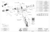
10 Spare parts ............................................................................................................................... 53
10.1 Doseur E dispense L1K .............................................................................................................. 53

4
Evolution table of the
document
Recording revisions
Editor
Object
Revision
Date
Aimed by
F SEGUIN Valve B - Draft -
beta test
Week 45/2019 B Batllo
F SEGUIN Valve C - Beta test Week 09/2020 B Batllo
F SEGUIN Valve D - Beta test Week 24/2020 B Batllo
F SEGUIN Valve E Week 46/2020 B Batllo
F SEGUIN Valve F Week 09/2021 B Batllo
Dear customer, you have just purchased your new equipment and
we thank you for it.
We have taken the utmost care, from design to manufacture, so that
this equipment gives you complete satisfaction.
For a good use and an optimal availability, we invite you to read this
manual carefully before commissioning your equipment.
Supplementary notice
Designation
Reference
E-dispense L1K shotmeterer
582111110-EN
Note: Consult the shotmeter and heating block
supplementary manuals separately before using the
system.

Safety instructions
5
1 Safety instructions
1.1 Personal safety
Overview
Read all operating instructions and device labels carefully
before putting the equipment into service.
Personnel using this equipment must have been trained in its use.
The workshop manager must ensure that the operators have fully
understood all the instructions and safety rules of this equipment and
other elements and accessories of the installation.
Misuse or operation can cause serious injury. This material is for
professional use only. It must be used only for the purpose for which it
was intended.
Do not modify or transform the material. Parts and accessories must
only be supplied or approved by SAMES KREMLIN.
The equipment must be checked periodically. Defective or worn parts
must be replaced.
Never exceed the maximum working pressures of the equipment
components.
Always respect the laws in force regarding security, fire, electricity of
the destination country of the equipment.
Only use products or solvents compatible with the parts in contact
with the product (see product manufacturer's technical data sheet).

Safety instructions
6
Meaning of the pictograms
Danger pinching,
crushing
Danger moving
parts
Danger: high pressure
Risks of product
emanation
Danger: hot parts or
surfaces
Danger: flammability
hazard
Danger: electricity
Risk of explosion
Danger (user)
Glasses required
Gloves required
Grounding

Safety instructions
7
Security devices
Attention
Guards (motor cover, coupling guard, housings, ...) are
installed for safe use of the equipment.
The manufacturer can not be held responsible for any bodily
injury as well as failures and / or damage to the equipment
resulting from the destruction, the occultation or the total or
partial removal of the protectors.
Never exceed the maximum working pressures of the
equipment components.
Pressure hazards
Safety requires that a decompression air shutoff valve be mounted on
the pump motor supply circuit to allow trapped air to escape when
the supply is shut off.
Without this precaution, the residual air from the engine may cause
the motor pump to operate and cause a serious accident.
Similarly, a product purge valve must be installed on the product
circuit in order to be able to purge it (after shutting off the engine air
and its decompression) before any intervention on the equipment.
These valves should remain closed for air and open for the product
during the procedure.

Safety instructions
8
Injection hazards
"HIGH PRESSURE" technology requires the utmost care.
Operation can cause dangerous leaks. There is a risk of product
injection into exposed parts of the body, which can lead to serious
injury and the risk of amputation:
An injection of product into the skin or other parts of the
body (eyes, fingers ...) must be treated urgently by
appropriate medical care.
Do not look at the gun nozzle when it is under pressure.
Never direct the jet to another person.
Never attempt to stop the jet with the body (hands, fingers
...) or with rags or similar.

Safety instructions
9
Fire hazards, explosion,
electric arc, static
electricity
Improper grounding, insufficient ventilation, open flames or sparks can
cause an explosion or fire which could result in serious injury.
To avoid these risks, especially when using pumps, it is imperative:
to connect the equipment, the parts to be treated, the cans
of products and cleaners to the ground,
to ensure good ventilation,
keep the work area clean and free of rags, papers, solvents,
do not operate electrical switches in the presence of vapors
or during removal,
immediately stop the application in the presence of arcs,
store all liquids outside the work areas.
use products whose flash point is as high as possible to avoid
any risk of formation of flammable gases and vapors
(consult the product safety data sheets).
to equip the drums with a lid to reduce the diffusion of gases
and vapors in the cabin.
It is forbidden to pump explosive materials
Hazards
toxic products
Toxic products or vapours can cause serious injury through contact
with the body, in the eyes, under the skin, but also by ingestion or
inhalation. It's imperative :
to know the type of product used and the dangers it
represents,
store the products to be used in appropriate areas,
contain the product used in the application in a container
designed for that purpose,
evacuate the products in accordance with the legislation of
the country where the equipment is used,
to wear protective clothing designed for that purpose,
wearing goggles, hearing protectors, gloves, shoes,
coveralls and masks for the respiratory tract.

Safety instructions
10
Attention
The use of halogenated hydrocarbon solvents and
products containing these solvents in the presence of
aluminium or zinc is prohibited.
Failure to follow these instructions exposes the user to the
risk of explosion resulting in serious injury or death.

Safety instructions
11
Valve
Recommendations for the valve.
Before starting up or using the shotmeter, carefully read the
DECOMPRESSION PROCEDURE.
Check that the decompression and purge air valves are
working properly.
Valve
Only use genuine SAMES KREMLIN accessories and spare
parts designed to withstand the operating pressures of the
valve.
Mandatory PPE (glasses + gloves + safety shoes).
Tubing
Recommandations for pipes.
Keep hoses away from traffic areas, moving parts and hot
areas.
Never subject product hoses to temperatures above 80 ° C
or below 0 ° C.
Do not use hoses to pull or move equipment.
Tighten all connections and hoses and connectors before
commissioning the equipment.
Check hoses regularly, replace them if damaged.
Never exceed the maximum operating pressure stated on
the hose (PMS).
For fitting the hoses and gun: PPE is mandatory.
Tighten to block stop. (Pipes + Pistol)

Safety instructions
12
Products implemented
Given the diversity of the products implemented by the users and the
impossibility of listing all the characteristics of the chemical
substances, their interactions and their evolution over time
SAMES KREMLIN can not be held responsible:
The poor compatibility of materials in contact.
inherent risks to staff and the environment.
Wear and tear, maladjustment, malfunction of equipment or
machines and the quality of the finished product.
The user will have to identify and prevent the potential dangers
inherent to the implemented products such as /
Toxic vapors
Fire.
Explosions.
It will determine the risks of immediate reactions or due to repeated
exposures to staff.
SAMES KREMLIN declines any responsibility, in case of:
Bodily or psychic injuries.
Direct or indirect material damage due to the use of
chemical substances.

Environment
13
2 Environment
The equipment is installed on a horizontal, stable and flat ground (eg
concrete slab).
Non-moving equipment must be fixed to the ground by suitable
fasteners (spit, screws, bolts, ...) to ensure their stability during use.
To avoid risks due to static electricity, the equipment and its
components must be grounded.
For dosing equipment (pumps, elevators, chassis, etc.), a
ground connector is available. Use this connector to
connect the equipment to the general "earth".
Have the earth continuity checked by a qualified
electrician. If earth continuity is not assured, check terminal,
wire and grounding point. Never operate the equipment
without solving this problem.
Do not store more flammable products than necessary
inside the work area.
These products must be stored in approved containers and
grounded.
Use only grounded metal buckets for the use of rinse
solvents.
Cartons and papers are to be banned. They are very bad
conductors, even insulators.

Presentation of the material
14
3 Presentation of the material
3.1 Equipment dimensions
Input valve

Technical characteristics and performances
15
4 Technical characteristics and performances
4.1 Technical characteristics
E Dispense L1K
Characteristics
Max product input pressure (bar) 500 bar / 7252 psi (feeding)
Max output pressure (bar) 500 bar / 7252 psi (place a string)
Air pressure (valve)
6 bar / 87 psi
Weight
4.7 kg / 10.36 lbs
Product connections
Product input (inlet valve)
M 3/4" G (optional M 1/2" G)
Product output
M1/2''G (optional M1/4''G)
Connections
Distributor Connectors
M 8
Instant connection for hose (feeding)
Ø 4x6

Installation
16
5 Installation
Valve
PNEUMATIC CONNECTIONS
Fit an air hose ( 4x6) to supply the valve with compressed air.
Connect it to the compressed air network via a pressure regulator.
ELECTRICAL CONNECTIONS
Connect the M8 connector control cable to the distributor
5.1 Connections
Make sure that all connections of the components of the
valve - cables, hoses and pipes - are installed in such a way
as to avoid causing a fall of people.
Make sure that the order of connection of cables, hoses and
hoses is in accordance with the connection diagram.
Ensure that all cable connectors, hose connectors and
hoses are properly in place.
Remember that loose or incorrectly connected cables,
hoses and pipes can lead to malfunctions that endanger
the safety of the operating personnel.
5.1.1 Product supply connection
If the supply pressure is higher than the max pressure, it is
necessary to install a product pressure regulator in front of
the valve.
Ensure that a short product hose reduces pressure
fluctuations and pressure drops.
5.1.2 Air supply connection
Ensure that a short air duct reduces pressure fluctuations
and pressure drops.

Installation
17
5.2 Storage
Valve
Storage before installation:
Place the equipment away from moisture.
Close the various air inlets and other openings with plugs.
Storage ambient temperature: 0 / +50 ° C.
Protect the unit against dust, water runoff, moisture and
shocks.
Storage after installation:
Operating temperature: +15 / +35 ° C.
Protect the unit against dust, water runoff, moisture and
shocks.

Commissioning
18
6 Commissioning
Valve
The valves are tested in our workshops with petroleum jelly before
shipping.
Before final commissioning, it will be necessary to purge the valve.
6.1 Prerequisite for commissioning
The valve works as a component of a product application system.
Ensure that the following preliminary functions are fulfilled to ensure
proper operation:
The entire product application system is completely
assembled and ready for operation.
The complete product application system is ventilated.
Power and pneumatic supply are in use.
The pump has a product supply at a sufficient boost
pressure.

Using the product
19
7 Using the product
7.1 User Settings
Valve
If the lubrication option has been selected, fill the lubricant reservoirs
"T".
7.2 Safety in production
Guards (motor cover, coupling guard,
housings, ...) are set up for safe use of the equipment.
The manufacturer can not be held responsible in case of
bodily injury as well as breakdowns and / or damage of
the material resulting from the destruction, the
occultation or the total or partial removal of the
protectors.

Using the product
20
7.3 Possible symptoms of faults / Causes of faults / Remedy to be
applied - rapid operation
Valve remedies
Defaults Possible causes Remedies
The material no longer flows
out
the valve outlet
Clogged valve outlet
Check, clean and unclog the valve
outlet if necessary
The inlet valve did
not open
Check the inlet valve, reassemble it or
replace it if necessary.
Refer to the
procedures for the Inlet and Outlet
Valve in the "Repair" section
Check the distributor command, and
the air supply. Change the distributor
if necessary.
Valve
open and no material
upstream
Check the material inlet at the valve
inlet
Product continuously flows
out of the valve
Valve closed,
no needle seal / seat holder
Remove and clean the seat needle,
check the condition and replace it if
necessary
Product
flows out through
the leak detector
Seal wear and tear
Replace the seals
/