Limit Switches, Plunger-Operated and Lever-Operated Bulletin No. 65013-037-27A
Class 9007 Type AW October 2001
4© 1994–2001 Schneider Electric All Rights Reserved
REPLACEMENT PARTS
When ordering replacement parts, specify quantity, Class, and Type
number. See Figure 3 on page 5.
Basic Contact Mechanism
The Class 9007 Type AO or Type CO snap switch (items 1 and 2 in
Figure 3 on page 5) serves as the contact mechanism. Replace it as a
complete unit.
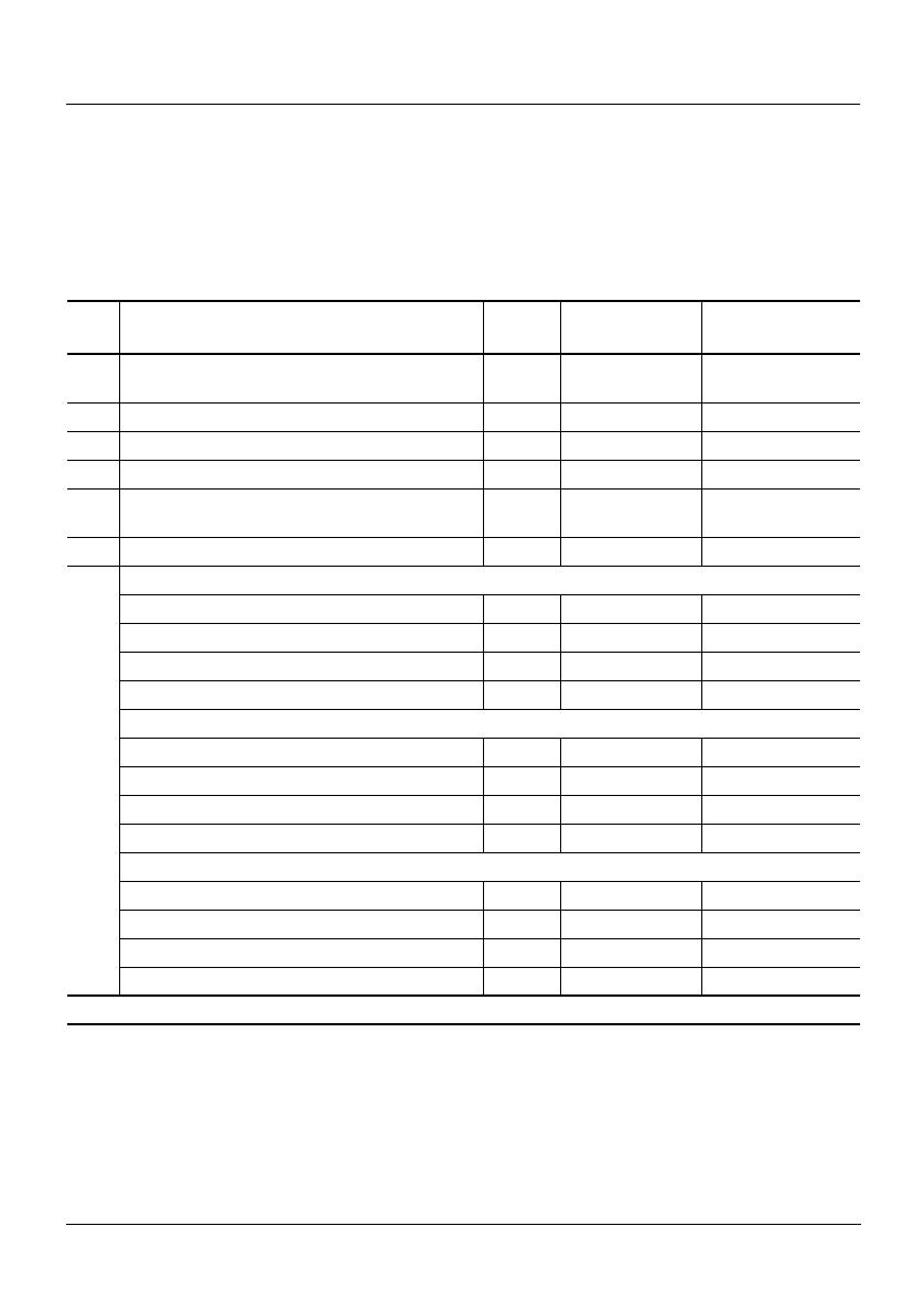
Table 2: Parts List
Item Description Class Type Used in Class
9007 Type
1 Snap Switch, Single Pole 9007 AO2 AW12, AW14, AW32,
AW34, AW42, AW44
2 Snap Switch, Single Pole Plug-in 9007 AO6 AW16, AW36, AW46
1 [1] Snap Switch, Double Pole 9007 CO3 AW18, AW38, AW48
2 [1] Snap Switch, Double Pole Plug-in 9007 CO6 AW19, AW39, AW49
3 Plug-in Terminal Block Assembly 9998 2441-S914-G1 AW16, AW19, AW36,
AW46, AW49
4 Gasket Kit 9998 2441-S913-G1 All Types
5
Limit Switch Mechanism—Roller Plunger Type
Single Pole Plug-in 9007 AO36 AW36
Double Pole Plug-in 9007 AO39 AW39
Single Pole Non-Plug-in 9007 AO32 AW32, AW34
Double Pole Non-Plug-in 9007 AO38 AW38
Limit Switch Mechanism—Push Rod Plunger Type
Single Pole Plug-in 9007 AO46 AW46
Double Pole Plug-in 9007 AO49 AW49
Single Pole Non-Plug-in 9007 AO42 AW42, AW44
Double Pole Non-Plug-in 9007 AO48 AW48
Limit Switch Mechanism—Lever Arm Type
Single Pole Plug-in 9007 AO16 AW16
Double Pole Plug-in 9007 AO19 AW19
Single Pole Non-Plug-in 9007 AO12 AW12, AW14
Double Pole Non Plug-in 9007 AO18 AW18
[1] Not shown in Figure 3 on page 5.


