


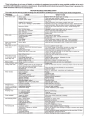
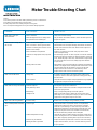
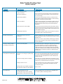
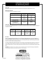
Motor Trouble-Shooting Chart
Caution:
1. Disconnect power to the motor before performing service or maintenance.
2. Discharge all capacitors before servicing motor.
3. Always keep hands and clothing away from moving parts.
4. Be sure required safety guards are in place before starting equipment.
Motor fails to start upon
initial installation.
Problem: What To Do:Like Causes:
Motor is miswired. Verify motor is wired correctly.
May be able to reassemble; otherwise, motor should be replaced.
Motor damaged and rotor is striking stator.
Replace fan guard.
Fan guard bent and contacting fan.
Motor has been running, then
fails to start. Fuse or circuit breaker tripped. Replace fuse or reset the breaker.
Stator is shorted or went to ground. Motor
will make a humming noise and the circuit
breaker or fuse will trip.
Disassemble motor and inspect windings and internal connections.
A blown stator will show a burn mark. Motor must be replaced or
the stator rewound.
Capacitor (on single phase motor) may have
failed.
Inspect to see that the load is free.Verify amp draw of motor
versus nameplate rating.
Starting switch has failed.
First discharge capacitor.To check capacitor, set volt-ohm meter to
RX100 scale and touch its probes to capacitor terminals. If capacitor
is OK, needle will jump to zero ohms, and drift back to high. Steady
zero ohms indicates a short circuit; steady high ohms indicates
an open circuit.
Motor runs but dies down. Voltage drop. If voltage is less than 10% of the motor’s rating contact power
company or check if some other equipment is taking power away
from the motor.
Verify the load has not changed.Verify equipment hasn’t got tighter.If
fan application verify the air flow hasn’t changed.
Load increased.
Motor takes too long to accelerate. Defective capacitor Test capacitor per previous instructions.
Faulty stationary switch. Inspect switch contacts and connections.Verify that switch reeds
have some spring in them.
Bad bearings. Noisy or rough feeling bearings should be replaced.
Motor runs in the wrong direction. Incorrect wiring.
Make sure that the voltage is within 10% of the motor’s name-
plate rating. If not, contact power company or check if some other
equipment is taking power away from the motor.
Motor overload protector continually
trips. Load too high.
Rewire motor according to wiring schematic provided.
Motor overloaded or load jammed.
Voltage too low.
Ambient temperature too high.
Protector may be defective.
Winding shorted or grounded.
Disassemble motor and inspect both the centrifugal and stationary
switches.The weights of the centrifugal switch should move in and
out freely. Make sure that the switch is not loose on the shaft.
Inspect contacts and connections on the stationary switch.
Replace switch if the contacts are burned or pitted.
Verify that the load is not jammed. If motor is a replacement,
verify that the rating is the same as the old motor. If previous
motor was a special design, a stock motor may not be able to
duplicate the performance. Remove the load from the motor and
inspect the amp draw of the motor unloaded. It should be less
than the full load rating stamped on the nameplate.
Verify that the motor is getting enough air for proper cooling. Most
motors are designed to run in an ambient temperature of less than
40°C.(Note: A properly operating motor may be hot to the touch.)
Replace the motor’s protector with a new one of the same rating.
Inspect stator for defects, or loose or cut wires that may cause it
to go to ground.

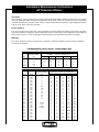
Motor vibrates.
Problem: What To Do:Like Causes:
Motor misaligned to load. Realign load.
Load out of balance.
(Direct drive application.) Remove motor from load and inspect motor by itself.Verify that
motor shaft is not bent. Rule of thumb is .001" runout per every
inch of shaft length.
Motor bearings defective. Test motor by itself. If bearings are bad, you will hear noise or
feel roughness. Replace bearings. Add oil if a sleeve of bearing.
Add grease if bearings have grease fittings.
Rotor out of balance.
Winding may be defective.
Inspect motor by itself with no load attached. If it feels rough and
vibrates but the bearings are good, it may be that the rotor was
improperly balanced at the factory. Rotor must be replaced or
rebalanced.
With the motor disconnected from power turned shaft. It should
move but with some resistance. If the shaft moves in and out too
freely, this may indicate a preload problem and the bearings may
need additional shimming.
Test winding for shorted or open circuits.The amps may also be
high. Replace motor or have stator rewound.
Bearings continuously fail. Load to motor may be excessive or
unbalanced. Besides checking load, also inspect drive belt tension to ensure it’s
not too tight may be too high.An unbalanced load will also cause the
bearings to fail.
High ambient temperature. If the motor is used in a high ambient, a different type of bearing
grease may be required.You may need to consult the factory or
a bearing distributor.
The motor, at start up, makes a
loud rubbing or grinding noise. Rotor may be striking stator. Ensure that motor was not damaged in shipment. Frame damage
may not be repairable. If you cannot see physical damage,
inspect the motor’s rotor and stator for strike marks. If signs of
rubbing are present, the motor should be replaced. Sometimes
simply disassembling and reassembling motor eliminates rubbing.
Endbells are also sometimes knocked out of alignment during
transportation.
Motor may not be sized properly.Verify how long the motor takes
to come up to speed, Most single phase capacitor start motors
should come up to speed within three seconds. Otherwise the
capacitors may fail.
Start capacitors continuously fail. The motor is not coming up to speed quickly
enough.
The motor is being cycled too frequently. Verify duty cycle. Capacitor manufacturers recommend no more
than 20, three-second starts per hour. Install capacitor with higher
voltage rating, or add bleed resistor to the capacitor.
Run capacitor fail.
Voltage to motor is too low. Verify that voltage to the motor is within 10% of the nameplate
value. If the motor is rated 208-230V, the deviation must be
calculated from 230V.
Motor Trouble-Shooting Chart
10/13/00 (continued)
Motor may have too much endplay.
Starting switch may be defective, preventing
the motor from coming out of start winding. Replace switch.
Ambient temperature too high.
Possible power surge to motor, caused by
lightning strike or other high transient voltage.
Verify that ambient does not exceed motor’s nameplate value.
If a common problem, install surge protector.
Bulletin 2400 10/00

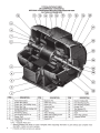
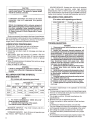
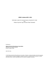
Lubrication
This motor is supplied with pre-lubrication ball bearings. No lubrication required before start up.
Relubrication Intervals
The following intervals are suggested as a guide:
Lubrication
Use high quality ball bearing lubricant. Use consistency of lubricant suitable for class of insulation stamped on
nameplate as follows:
Procedure
If motor is equipped with Alemite fitting, clean tip of fitting and apply grease gun. Use 1 to 2 full strokes on
motors in NEMA 215T frame and smaller. Use 2 to 3 strokes on NEMA 254T thru NEMA 365 T frame. Use 3
to 4 strokes on NEMA 404T frames and larger. On motors having drain plugs, remove drain plug and operate
motor for 20 minutes before replacing drain plug.
On motors equipped with slotted head grease screw, remove screw and apply grease tube to hole. Insert 2 to
3 inch length of grease string into each hole on motors in NEMA 215T frame and smaller. Insert 3 to 5 inch
length on larger motors. For motors having drain plug and operate motor for 20 minutes before replacing drain
plug.
CAUTION: Keep lubricant clean. Lubricate motors at standstill. remove and replace drain plugs at standstill. Do
not mix petroleum lubricant and silicone lubricant in motor bearings.
Lubrication Instructions
For Ball Bearing Motors
H.P. RANGE
Sub Fractional to 7 1/2
10 to 40
50-200
Sub Fractional to 7 1/2
10 to 40
50 to 200
All
Sub Fractional to 40
50 to 200
SUGGESTED RELUBRICATION INTERVALS
HOURS OF SERVICE PER YEAR
5,000
Continuous Normal Applications
Season Service Motor
Idle 6 Months or More
Continuous High Ambients
Dirty or Moist Locations
High Vibrations
Where Shaft End is Hot (Pumps-Fans)
RELUBE INTERVAL
5 Years
3 Years
1 Year
2 Years
1 Year
9 Months
1 Year
(Beginning of Season)
6 Months
3 Months
300-088.02
CONSISTENCY
Medium
LUBRICATION CONSISTENCY
INSULATION
CLASS
B & F
F & H
TYPICAL
LUBRICATION
Shell Dolium R
and/or
Chevron SR1 2
FRAME
TYPE
Sub Fractional
to 447T
All
TYPE
Polyurea

100
12
12
12
12
12
12
10
12
8
12
6
12
4
12
4
10
2
8
2
8
1
6
1
4
1
4
0
4
150
12
12
12
12
10
12
8
12
6
12
4
12
4
10
2
8
2
8
1
6
0
6
0
4
00
2
000
2
200
12
12
12
12
10
12
8
12
6
12
4
12
4
10
2
8
2
6
1
6
00
4
00
2
000
2
0000
0
300
12
12
10
12
8
12
6
10
4
10
4
10
2
8
1
6
0
6
00
4
0000
2
0000
2
250
0
300
00
500
10
12
8
12
6
10
4
8
2
8
1
8
0
6
000
4
000
4
0000
2
300
0
300
0
500
00
500
000
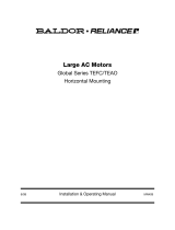
SINGLE PHASE MOTORS - 230 VOLTS
H.P.
1 1/2
2
3
5
7 1/2
100
10
10
8
6
6
150
8
8
8
4
4
200
8
8
6
4
3
300
6
6
4
2
1
500
4
4
2
0
0
TRANSFORMER
KVA
3
3
5
7 1/2
10
DISTANCE - MOTOR TO TRANSF. IN FT.
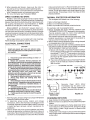
Installation
After unpacking, check for damage. Be sure that shaft rotates freely. Before making electrical power connections,
check for proper grounding of motor and application. All electrical contacts and connections must be properly
insulated and enclosed. Couplings, belts, chains or other mounted devices must be in proper alignment, balance
and secure to insure safe motor operation.
Electrical Wiring
Prior to connecting to the power line, check nameplate for proper voltage and rotation connection.This motor
should be installed in compliance with the National Electrical Code and any other applicable codes.Voltage at
motor not to exceed + or -10% of nameplate. Authorized person should make all electrical connections.
Mounting
This motor should be securely mounted to the application. Sufficient ventilation area should be provided to
insure proper operation.
RECOMMENDED COPPER WIRE & TRANSFORMER SIZE
Installation Maintenance Instructions
AC Induction Motors
VOLTS
230
460
230
460
230
460
230
460
230
460
230
460
230
460
230
460
230
460
230
460
230
460
230
460
230
460
230
460
THREE PHASE MOTORS - 230 & 460 VOLTS
H.P.
1 1/2
1 1/2
2
2
3
3
5
5
7 1/2
7 1/2
10
10
15
15
20
20
25
25
30
30
40
40
50
50
60
60
75
75
TRANSFORMER
KVA
3
3
3
3
5
5
7
1/2
7 1/2
10
10
15
15
20
20
Consult
Local
Power
Company
DISTANCE - MOTOR TO TRANSF. IN FT.
-
 1
1
-
 2
2
-
 3
3
-
 4
4
-
 5
5
-
 6
6
-
 7
7
-
 8
8
-
 9
9
-
 10
10
-
 11
11


Leeson 102891 Owner's manual
- Type
- Owner's manual
Ask a question and I''ll find the answer in the document
Finding information in a document is now easier with AI
Other documents
-
Marathon 5KCP33KNB267AS AC Induction Motors User manual
-
 Regal Beloit Water Pump Pool & Spa Motor User manual
-
In-Sink-Erator SS-100-28 User manual
-
GE gei-m1031 Installation and Maintenance Manual
-
 NEMA MG 1-2011 Information Manual
-
Pentek ELECTRONICS Owner's manual
-
-
 Baldor-Reliance Above NEMA DutyMaster AC Motors (Horizontal & Vertical) Owner's manual
-
 Baldor-Reliance Above NEMA Duty Master AC Motors Owner's manual
-
 Baldor-Reliance Large AC Motors Global Series TEFC/TEAO Horizontal Mounting Owner's manual


