Page is loading ...

SAM Series
Inverter /
Charger
SAM-1500C-12
Please read this
manual BEFORE
installing your
inverter
Owner's
Manual

2 | SAMLEX AMERICA INC.
SECTION 1
Safety Instructions ...............................................................................................3
SECTION 2
Features, Applications & Principle of Operation ..................................................5
SECTION 3
Layout .......................................................................................................12
SECTION 4
Installation ...................................................................................................... 14
SECTION 5
Operation .......................................................................................................23
SECTION 6
Protections, Monitoring & Troubleshooting .......................................................30
SECTION 7
Specications ....................................................................................................37
SECTION 8
Warranty .......................................................................................................38
OWNER'S MANUAL | Index
Disclaimer of Liability
UNLESS SPECIFICALLY AGREED TO IN WRITING, SAMLEX AMERICA, INC.:
1. MAKES NO WARRANTY AS TO THE ACCURACY, SUFFICIENCY OR SUITABILITY OF ANY TECHNICAL OR OTHER INFORMATION
PROVIDED IN ITS MANUALS OR OTHER DOCUMENTATION.
2. ASSUMES NO RESPONSIBILITY OR LIABILITY FOR LOSSES, DAMAGES, COSTS OR EXPENSES, WHETHER SPECIAL, DIRECT,
INDIRECT, CONSEQUENTIAL OR INCIDENTAL, WHICH MIGHT ARISE OUT OF THE USE OF SUCH INFORMATION. THE USE OF
ANY SUCH INFORMATION WILL BE ENTIRELY AT THE USERS RISK.
Samlex America reserves the right to revise this document and to periodically make changes to the content
hereof without obligation or organization of such revisions or changes.
Copyright Notice/Notice of Copyright
Copyright © 2016 by Samlex America, Inc. All rights reserved. Permission to copy, distribute and/or modify this
document is prohibited without express written permission by Samlex America, Inc.

2 | SAMLEX AMERICA INC. SAMLEX AMERICA INC. | 3
SECTION 1 | Safety Instructions
1.1 IMPORTANT SAFETY INSTRUCTIONS
This manual contains important information regarding safety, operation, maintenance
and storage of this product. Before use, read and understand all cautions, warnings,
instructions and product labels, plus your vehicle’s battery manufacturer’s guidelines.
Failure to do so could result in injury and / or property damage. The following safety
symbols will be used in this manual to highlight safety and information:
WARNING!
Indicates possibility of physical harm to the user in case of non-compliance.
!
CAUTION!
Indicates possibility of damage to the equipment in case of non-compliance.
i
INFO
Indicates useful supplemental information.
WARNING!
To reduce the risk of re, electric shock, explosion or injury:
1. Do not connect in parallel with another AC source e.g. Utility AC Distribution
Wiring / generator. This is NOT a Grid Tied Inverter!
2. When working with Multiple Outlet Power Strips, disconnect appliance
plug from outlet strip or turn off the inverter before working on the ap-
pliance. Multiple Outlet Power Strips with switches and circuit breakers
interrupt power only to the “Hot” receptacle terminals.
3. Precautions when working with batteries
• BatteriescontainverycorrosivedilutedSulphuricAcidaselectrolyte.
Precautions should be taken to prevent contact with skin, eyes or
clothing.
• BatteriesgenerateHydrogenandOxygenduringchargingresult-
inginevolutionofexplosivegasmixture.Careshouldbetakento
ventilate the battery area and follow the battery manufacturer’s
recommendations.
• Neversmokeorallowasparkoramenearthebatteries.
• Usecautiontoreducetheriskofdroppingametaltoolonthe
battery. It could spark or short circuit the battery or other electrical
partsandcouldcauseanexplosion.
• Removemetalitemslikerings,braceletsandwatcheswhenworking
with batteries and also use caution when working with metal tools.
Batteries can produce a short circuit current high enough to melt /
weld metals and thus, cause severe burn.

4 | SAMLEX AMERICA INC.
• Ifyouneedtoremoveabattery,alwaysremovetheGround(Nega-
tive) terminal from the battery rst. Make sure that all the accesso-
ries are off so that you do not cause a spark.
4. Do not make any electrical connections or disconnections in areas desig-
nated as IGNITION PROTECTED. Thisincludes12VDCPowerPlug(Cigarette
Plug) connections and terminal connections.
5. This is not a toy - keep away from children.
6. Do NOT insert objects into the ventilation air vents.
!
CAUTION!
1. Please ensure that the Grid AC Power input is fed from 15A/20A GFCI
protected outlet to provide Ground Fault Protection when the unit is oper-
ating in Charger / Grid AC Pass Through Mode
2. ConnecttheexternalChassisGroundConnection(15,Fig3.1)toEarth
Ground using at least AWG #8 wire.
3. When Inverter is supplying AC loads, the voltage on the Neutral and Line
Socket of the NEMA5-15R AC outlet with respect to the Ground Socket /
metal chassis of the unit / metal chassis of the AC loads will be a pulsing
DCvoltagewithaverageDCvalueofupto50V(willfalselyread75VAC
on AC scale of the Voltmeter because of pulsing nature of DC voltage). DO
NOT TOUCH THE NEUTRAL SOCKET / NEUTRAL CONDUCTORS OF THE AC
OUTLETS!
4. Do not connect AC output from NEMA5-15R outlets to AC distribution wir-
ing where the Neutral is bonded to Earth Ground. The inverter will see this
as abnormal condition of Ground Fault and will shut down.
5. DonotusewithPositiveGroundedElectricalSystems(themajorityofmod-
ern automobiles, RVs, trucks and boats use Negative Grounded Electrical
Systems).
6. Observe correct polarity when connecting the DC input terminals of the
inverter to the battery. Connect Positive of the battery to the Positive input
connector of the Inverter and the Negative of the battery to the Negative
input terminal of the Inverter. Reverse polarity connection will result in a
blown fuse and may cause permanent damage to the inverter. Damage
due to reverse polarity is not covered under warranty.
7. ThisInverterwillnotoperatehighwattageappliancesthatexceedthe
output power limit or the surge power limit.
8. Do not operate this Inverter if it is wet.
9. Do not install in engine compartment – please install in a well-ventilated area.
10. This Inverter is not tested for use with medical devices.
SECTION 1 | Safety Instructions

4 | SAMLEX AMERICA INC. SAMLEX AMERICA INC. | 5
2.1 GENERAL
i
INFO
For additional technical and operational information on Inverters, Battery
Chargers and related topics, please refer to www.samlexamerica.com/
Support/Application Notes/White Papers.
This unit is a Modied Sine Inverter / Charger with a Transfer Relay with primary
function of Backup AC Power Source. The unit consists of the following 3 components
integrated into a single unit:
• ModiedSineWaveInverterforACbackupwhenGridACPowerfails:
• Input:12VNominalLeadAcidBattery(10.5Vto15.5V±0.5V)
• Output:1500W(AtPowerFactor=1)at115VAC,60Hz
• ACBatteryChargertochargebatterieswhenGridACPowerisavailable:
• Input:120VAC,60Hz
• Output:13.8VDC,15Atocharge12VLeadAcidBatteries-Flooded,AGMorGel
Cell
• 2-StageCharging-BulkandFloat
• ACInputPassThroughtoloadwhenGridACPowerisavailable
• Input:120VAC,60Hz,15A
• TransferRelayRating:30A
2.2 APPLICATIONS
• BackupACPowerSourceorOff-LineACUPStoprovideACpowerduringpoweroutages
• 12VLeadAcidBatterycharging
• RVs,trucksandremotehousing
2.3 FEATURES
• Integrated 1500W Modied Sine Wave Inverter, 30A rated Transfer switch, and 2
Stage 12 VDC, 15A Battery Charger
• HighInverterpeakefciencyof87%,lightweight,andcompactforeasyinstallation
• SoftStartTechnologyforbettersurgeperformance
• SeparateON/OFFcontrolforInverterandBatteryChargerforselectableoperationas
Inverter/Charger(BackupACPowerSource)orStand-aloneInverterorStand-alone
Battery Charger
• 4LEDindicatorstomonitoroperationalstatus
• Loadcontrolledfanforefcientcoolingwhenrequired
• Allowsuseofhighercapacityexternal12Vbatterybankforlongerbackuptime
• CoolSurfaceTechnologyforcoolerandsafertouchtemperature
• ElectronicprotectionsincludingGFCIwheninInverterMode
SECTION 2 | Features, Applications &
Principle of Operation

6 | SAMLEX AMERICA INC.
SECTION 2 | Features, Applications &
Principle of Operation
• LowInterferenceTechnologyforcontrolledRFnoise
• IdealforRV’s,Trucksandremotehousing
2.3.1 Soft Start Technology
This feature offers the following advantages:
• WhentheInverterisswitchedON,thevoltagerampsupto115VACinaround2sec.
If the load was already ON at the time of switching ON of the Inverter, starting surge
current demanded by certain reactive devices like motors etc. will be reduced and
there will be less likelihood of the Inverter shutting down due to overload.
• IftheInverterisswitchedONrstandthenaloadwithhigherstarting/inrushcur-
rent like SMPS / motor is switched ON, the voltage will dip momentarily and then
recover to reduce inrush / starting surge current in the load as above.
• Similaroverloadreductionwillbeinitiatedduringanyothersuddenhigher
loading conditions.
2.3.2 Low Interference Technology
Innovative circuit design and noise ltration circuitry reduces RF interference in TV
picture, audio and radio equipment.
2.3.3 Cool Surface Technology
Normally, heat dissipating components are mounted directly on internal metal chassis
surface of the unit and hence, the chassis surface may rise to unsafe touch-temperature.
In this unit, heat-dissipating components are not mounted directly on the chassis of the
unitbutonPCB(PrintedCircuitBoard)mountedheatsinkand,thereisairgapbetween
the heat sink and the chassis surface. The heat sink is cooled by load-controlled fan.
As there is no direct contact between the heat sink and the chassis, the chassis surface
remains much cooler and is safer to touch.
2.3.4 Load Controlled Cooling Fans
Cooling is carried out by convection and by forced air circulation by 2 load-controlled
fan. The fan will normally be OFF and will be switched ON automatically as follows:
• InvertersupplyingACload(s):Whenload(s)≥85W
• BatteryCharging/ACPassThroughMode:Whenchargingcurrent≥3A±1A
This will reduce energy consumption by the fan and will increase overall efciency.
2.4 PRINCIPLE OF OPERATION - INVERTER
Conversion of 12 VDC from the battery / other DC source to 115 VAC takes place in 2
stages.Intherststage,the12VDCisconvertedtohighvoltageDC(around160VDC)
usinghighfrequencyswitchingandPulseWidthModulation(PWM)technique.Inthe
2ndstage,the160VhighvoltageDCisconvertedto115V,60HzModiedSineWave
AC.(NOTE: 115V is the RMS value of the Modied Sine Wave AC voltage. The peak
value of the Modied Sine Wave AC voltage will be equal to the value of the above
high voltage of around 160V. See the Fig 2.1).

6 | SAMLEX AMERICA INC. SAMLEX AMERICA INC. | 7
SECTION 2 | Features, Applications &
Principle of Operation
SECTION 2 | Features, Applications &
Principle of Operation
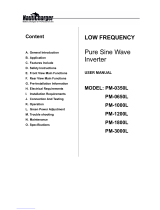
2.4.1. Modied Sine Waveform - Characteristics & Comparison with
Pure Sine Waveform
Please refer to Fig 2.1 below which shows one cycle of Modied Sine Wave and Pure
SineWaveforcomparison.(BothwithRMSvoltageof115VAC)
TIME
180
160
140
120
100
80
60
40
20
0
20
40
60
80
100
120
140
160
180
Modied Sine
Wave sits at
ZERO for some
time and then
rises or falls
Pure Sine Wave
crosses zero V
instantaneously
Modied Sine Wave
• V
RMS
= 115VAC
• V
peak
= 160V ± 5V
Sine Wave
• V
RMS
= 115VAC
• V
peak
= 162.61V
16.66 ms
VOLTS − VOLTS +
V
peak
= 162.61V
V
peak
= 160V ± 5V
V
RMS
= 115 VAC
Fig 2.1 Modied Sine Wave and Pure Sine Wave - Comparison
The output waveform of the Inverter is a Modied Sine Wave. In a Modied Sine Wave,
thevoltagewaveformconsistsofrectangularpulsesthatapproximatesinewavepulses
of a Pure Sine Wave. The voltage rises and falls abruptly at a particular phase angle
and sits at 0 Volts for some time before changing its polarity. In a Pure Sine Wave, the
voltage rises and falls smoothly with respect to phase angle and the voltage changes its
polarity instantly when it crosses 0 Volts.
!
CAUTION!
Certaindevices(fewexamplesgivenbelow)maymalfunctionwhenpowered
from Modied Sine Wave. Check with the manufacturer of the device for suit-
ability of powering with Modied Sine Wave:
• Devicesutilizingzerovoltagecrossingfortimingcontrol:Someclocksused
inconsumerelectronicitems(willnotkeepaccuratetime)
• DevicesusingmodulationofRFsignalsonAClinesduringzerocrossinge.g.
X-10 System for Home Automation
• DevicesutilizingTriacbasedphasecontrolfortransformerlessvoltagestep
down e.g.:
• Smallbatterychargersforhandtools,ashlights,night-lights,shaversetc.
• Variablemotorspeedcontrolinhandtools
• Lightdimmers

8 | SAMLEX AMERICA INC.
SECTION 2 | Features, Applications &
Principle of Operation
• Temperaturecontrollerse.g.:
• TemperatureControlledElectricBlankets
• Devicesusinghighcapacitancebasedvoltagemultipliersforgeneratinghigh
voltage(willcreateveryhighsurgecurrents)e.g.:
• PhotographicStrobeLights
• LaserPrinters
2.4.2 Measuring Modied Sine Wave Voltage with a "True RMS"
Voltmeter
As mentioned above, Modied Sine Wave voltage is a type of square wave that has an
RMS(RootMeanSquare)valueof115VACinthisInverter.Ageneral-purposeACvolt-
meter is calibrated to accurately measure the RMS value of a Pure Sine Wave and NOT
of a Modied Sine Wave. If this general-purpose voltmeter is used to measure Modied
Sinewavevoltage,itwillindicatealowervalue(96VACto104VAC).Foraccurately
measuring the voltage of a Modied Sine Wave, use a voltmeter which is designed to
measure“TrueRMSValues”likeFluke87,Fluke8060A,Fluke77/99,Beckman4410etc.
2.5 PRINCIPLE OF OPERATION AND CHARGING ALGORITHM - BATTERY
CHARGER
The battery charger is a 2 Stage, Switched Mode Design using Fly Back Topology.
120VACfromtheACInputisrectiedtohighvoltageDCofaround170VDC,which
is then converted to high frequency pulses using MOSFET Switch and then stepped
down through switching transformer. The transformed voltage is rectied and ltered.
A sample of the output voltage is used as feedback signal for the drive circuit for the
switching Mosfet to achieve desired voltage regulation of 13.8 VDC using Pulse Width
Modulation(PWM).Itisdesignedtoprovidemaximumchargingcurrentof15A.
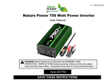
2.5.1 Charging / Discharging Curves for Lead Acid Batteries
Fig. 2.2 shows the charging and discharging characteristics of a typical 12V / 24V Flooded
LeadAcidbatteryatelectrolytetemperatureof80°F/26.7°C.Thecurvesshowthe%
StateofCharge(X-axis)versusterminalvoltage(Y-axis)duringcharginganddischarging
at different "C-Rates". Please note that X-axis shows % State of Charge. State of Dis-
charge will be = 100% - % State of Charge. The value of charging / discharging curent is
expressedas"C-Rate"whichisaratioasdenedbelow:
C-Rate in Amperes =
C
T
where,
C= CapacityofthebatteryinAmpereHours(Ah)
T=TimeinHoursoverwhichthebatteryindischargedfromfullychargedconditionto
10.5V(12Vbattery)or21V(24Vbattery)atconstantcurrent=C-Rate e.g. if 100Ah
battery(C=100)isdischargedin5Hours(T=5)theC-Rate=
100
5
=20Amperes

8 | SAMLEX AMERICA INC. SAMLEX AMERICA INC. | 9
SECTION 2 | Features, Applications &
Principle of Operation
SECTION 2 | Features, Applications &
Principle of Operation
Typical Flooded Lead-Acid Battery Chart - 80˚F / 26.7˚C
Battery Voltage in VDC
Battery State of Charge in Percent (%)
0 10 20 30 40 50 60 70 80 90 100 110 120 130
16.5
16.0
15.5
15.0
14.5
14.0
13.5
13.0
12.5
12.0
11.5
11.0
10.5
10.0
9.5
9.0
C/5
C/40
C/20
C/10
DISCHARGE
CHARGE
C/20
C/3
C/5
C/10
C/100
33.0
32.0
31.0
30.0
29.0
28.0
27.0
26.0
25.0
24.0
23.0
22.0
21.0
20.0
19.0
18.0
24V 12V
Standing
Voltage
Fig 2.2 Charging / Discharging Curves for Typical Flooded Lead Acid Battery

10 | SAMLEX AMERICA INC.
2.5.2 2 Stage Charging - Bulk Charge and Float Charge Stages
The built-in Battery Charger is a "2 stage charger".
Workingofa2StageChargerisexplainedbelow.PleaserefertoFig2.3.
Bulk Charge
Stage
Float Charge
Stage
Charger Current Curve
Charger Voltage Curve
Time
Voltage
Current
9
10
11
12
13
14
1
1
2
2
3
3
15A
0A
LEGEND
1. Charging Starts
1 to 2. Bulk Charge Stage: Constant Current = 15A
2. Exits Bulk & enters Float
2 to 3. Foat Stage: Constant Voltage = 13.8V
Current tapers to 0.25% of Ah Capacity
13.8V
5A
10A
20A
Fig. 2.3 Battery Charger Stages and Voltage/Current Curves
2StagesofChargingare(i)ConstantcurrentBulkStageand(ii)ConstantvoltageFloat
Stage.A2-StageChargerisabletorechargeabatterytoaround80%capacity.Thistype
of charger is used in Backup / UPS applications where the battery remains charged, is
oatingmostofthetimesandwilldischargeatlesserfrequencyonlyduringpowerout-
ages. Charging details are given below:
i. Thechargeroutputsaconstant,regulatedvoltageof13.8V(FloatChargeStage
Voltage)andcandeliverupto15Aofmaximumchargingcurrent(BulkChargeStage
Current). If the battery tries to draw current higher than 15A due to its discharged
condition, the charger enters Current Limit Condition. Under Current Limit Condition,
the charger will supply constant current of 15A, its output voltage will no longer be
regulated and will drop below 13.8V. However, its output voltage will get clamped to
the battery voltage corresponding to the State of Charge of the battery.
ii. The input resistance of a healthy battery is very low – around 16 milli Ohm at com-
pletely discharged condition to less than 8 milli Ohm when fully charged
SECTION 2 | Features, Applications &
Principle of Operation

10 | SAMLEX AMERICA INC. SAMLEX AMERICA INC. | 11
SECTION 2 | Features, Applications &
Principle of Operation
iii. The “Standing Voltage” of a battery is the terminal voltage of the battery after it has
“rested”foratleast4hours(nochargingordischargingduringrestingperiodof4
hours).TheStandingVoltagesof12VLeadAcidbatteryareasfollows(SeeFig2.2):
- Fully Charged: Around 12.8V
- Fully discharged: Around 11.8V
iv. BeforethechargerisswitchedON(beforePoint1inFig2.3),thebatteryisalmost
completelydischargedto“StandingVoltage”ofaround11.8V(Fig2.2)anditsinter-
nal resistance is, say 16 milli Ohm. Assuming 4 milli Ohm of battery wire resistance, a
resistance of 20 milli Ohm will be seen by the charger when it is initially switched ON.
WhenthechargerisswitchedON(Point1inFig2.3),13.8Vfromthechargerisfed
tothebattery.Voltagedifferenceof2.0V(13.8V-11.8V)willinitiallyTRYtodrivevery
largechargingcurrentofaround100Aintothebattery(2.0V÷20milliOhm=100A).
However, the charger will limit the current to 15A will enter Current Limit Condition
asexplainedatparagraph(i)aboveanditsvoltagewillbeclampedtotheactualbat-
tery voltage i.e. 11.8V. This is the start of the “Bulk Charge Stage”
v. Continuous15Aconstantcurrentcharginginthe“BulkChargeStage”(Points1to2
of Fig 2.3) will slowly raise the battery voltage. As the battery voltage rises, the volt-
age difference between the charger’s Float Stage Voltage setting of 13.8V and the
battery’s actual voltage reduces. The internal resistance of the battery also reduces.
When the battery voltage rises to around 13.6V, the charging current will reduce
below15AandthechargerwillexitCurrentLimitCondition-itsvoltagewillrise
toconstant,regulatedFloatVoltageof13.8V(Point2inFig2.3).Atthispoint,the
chargerwillexittheconstantcurrent“BulkChargeStage”andentertheconstant
voltage “Float Charge Stage”.
vi.Duringthe“FloatChargeStage”(Points2to3inFig2.3),thebatteryischargedat
constant voltage of 13.8V. The charging current tapers from 15A to low steady state
FloatChargeCurrentofaround0.25%oftheAmpereHour(Ah)capacityofthebat-
tery(Point3inFig2.3).At13.8V,thebatteryischargedtoaround80%ofitsrated
capacityatC/10ChargeRate(Fig2.2).
SECTION 2 | Features, Applications &
Principle of Operation

12 | SAMLEX AMERICA INC.
SECTION 3 | Layout
Fig 3.1 Layout and Input/Output Connections
AC INPUT/OUTPUT SIDE
5
4
1
14
2 3
6 7 8 9
10A
LEGEND
1. AC Outlet - NEMA5-15R
2. ON/OFF Switch - Charger
3. ON/OFF Switch - Inverter
4. Breaker for AC Input - 15A
5. Fuse for Charger Section - 5A, 125V / 250V
6. YELLOW LED for Input Fault
7. GREEN LED for Charger ON
8. GREEN LED for Inverter ON
9. RED LED for Fault
10A. & 10B.
AC Input Cord - 6 ft. 10A with
NEMA5-15P Plug (10B)
11. Negative Input Terminal (M9) for 12V
Battery Negative
11a. BLACK plastic cover for Negative
Input Terminal
12. Positive Input Terminal (M9) for
12V Battery Positive
12A. RED plastic cover for Positive
Input Terminal
13. Opening for cooling fan discharge
14. Ventilation slots for air inlet
15. Chassis Ground Connection, M5
16. 200A, Class-T / MRBF Fuse (within 7”
of Positive Battery Terminal)*
17. AWG#2 Battery Cables (see Table 4.1
for voltage drops)*
* Not included
1
DC INPUT SIDE
13
15
13
11A 12A
11
12
+–
12V Battery
16
1717
10B
Grid AC Power
Outlet
3.1 LAYOUT
LEGEND
1. AC Outlet - NEMA5-15R
2. ON/OFF Switch - marked “CHARGER”
3. ON/OFF Switch - marked “INVERTER”
4. Breaker for AC Input - 15A
5. Fuse for
Charger Section
6. YELLOW LED marked “INPUT FAULT”
7. GREEN LED marked “CHARGER”
8. GREEN LED marked “INVERTER”
9. RED LED marked “FAULT”
10A. AC input power cord; 3x AWG#14, 105ºC
10B. NEMA5-15P Plug for the power cord
11. Negative Input Terminal (M9) for 12V
Battery Negative
11a. BLACK plastic cover for Negative
Input Terminal
12. Positive Input Terminal (M9) for
12V Battery Positive
12A. RED plastic cover for Positive
Input Terminal
13. Opening for cooling fan discharge
14. Ventilation slots for air inlet
15. Chassis Ground Connection, M5
16. 200A, Class-T / MRBF Fuse (within 7”
of Positive Battery Terminal)*
17. AWG#2 Battery Cables (see Table 4.1
for voltage drops)*
* Not included
- 5 mm x 20 mm,
Fast Acting Glass Tube Fuse
- 5A, 125V ; Bussman
GMA-A or equivalent
{

12 | SAMLEX AMERICA INC. SAMLEX AMERICA INC. | 13
SECTION 3 | Layout SECTION 3 | Layout
12
6
SAM-1500C-12
Dimensions:
345 mm x 202 x 84 mm
13.54 x 7.87 x 3.35 inch
Weight: 4 kg / 8.8 lb
302
345
120
202
Fig 4.1: Dimensions of Mounting Arrangement
Fig 3.2 Dimensions & Mounting Arrangement
3.2 DIMENSIONS AND MOUNTING ARRANGEMENT

14 | SAMLEX AMERICA INC.
SECTION 4 | Installation
4.1 SAFETY OF INSTALLATION
WARNING!
Please read safety instructions in Section 1 before commencing installation.
When using the unit as a backup AC Power Source, Grid AC Power Input should
be fed from 15A/20A, GFCI Protected outlet.
4.2 INSTALLATION ENVIRONMENT
Forbestoperatingresults,theunitshouldbeplacedonatsurface,suchastheground,car
oor,orothersolidsurface.Thepowercordallowseasypositioningoftheunit.Theunit
should only be used in locations that meet the following criteria:
Dry- Do not allow water and/or other liquids to come into contact with the unit. In all ma-
rine applications, do not install the unit below or near the waterline and keep the inverter
away from moisture or water.
If Flooded / Wet Cell Type of battery is being used, ensure that the unit is not installed very
close to the battery to avoid contact with acid / acid vapors
Cool - Ambientairtemperatureshouldbebetween0°C(32°F)to25°C(77°F)forfullrated
power.Athighertemperatureof26°C(79°F)to35°C(95°F),theoutputpowershouldbe
de-ratedto80%.Donotplacetheunitonornearaheatingventoranypieceofequipment
which is generating heat above room temperature. Keep the unit away from direct sunlight.
Ventilated - The unit is cooled by 2 load-controlled fans. The fans will switch ON automati-
callyatload≥85WwhentheInverterissupplyingpower,andat3A±1Achargingcurrent
when in Battery Charging/AC Pass Through Mode. The fans draw cool air from the air
intakeventilationslotsontheACoutletside(14,Fig3.1)anddischargehotairoutofthe
fanopenings(13,Fig3.1)ontheDCInputTerminalside.Keeptheareassurroundingthe
inverter clear by at least 10 cm to ensure free air circulation around the unit. Ensure that the
air intake ventilation slots and fan openings for air discharge are not blocked. Do not place
other items on or over the unit during operation.
4.3 MOUNTING ORIENTATION
Two(2)angesonthebottomwith2mountingslotseachareprovidedformounting,as
shown in Fig 3.2.
If the unit is required to be mounted on a vertical surface like a wall, please ensure that the
fanaxisishorizontalasshowninFig4.1(a).
TheDCinputsidehaslargerventilationopenings(13,Fig3.1)forfanairdischarge.
MountingwiththefansidefacingupordownasshowninFigs4.1(b)or4.1(c)isNOT
permittedduetosafetyconsiderations.IfmountedasinFig4.1(b),metallicorother
conductiveobject(s)mayaccidentallyfallinsidetheunitthroughthefanventilation
openingsandcreatehazardousconditionresultingfromshortcircuitofinternalhigh
voltagesection(s).IfmountedasinFig4.1(c),hot/moltenmaterialfromdamaged
internal portion of the unit due to malfunction may fall on combustible material on the
oorandmaycreaterehazard.

14 | SAMLEX AMERICA INC. SAMLEX AMERICA INC. | 15
SECTION 4 | Installation
(a) (c)(b)
Fig 4.1
Mounting Orientation
on Wall
4.4 GROUNDING AND GROUND FAULT / LEAKAGE PROTECTIONS
4.4.1 DC Side Grounding and Ground Fault Protection
ForDCsidegroundingandprotectionagainstGroundFault,anM5BoltandNut(15,Fig3.1)
has been provided. Connect this to the Earth Ground in shore based installations / Vehicle
Chassis Ground using minimum AWG #8 wire.
4.4.2. AC Side Grounding and Leakage Protection
AC Side Grounding and Leakage Protection are provided as follows:
(i) Condition 1: AC input cord is plugged into GFCI protected Grid AC Outlet and Grid
Voltage is available at this outlet:
TheGroundingConductoroftheACinputcord(Greenwire)isinternallyconnected
to the metal chassis of the unit. Hence, the metal chassis of the unit will also get
connected to the Earth Ground in the Grid AC Supply Panel through the above
mentioned Grounding Conductor of the AC input cord. On detecting availability of
Grid input voltage, internal Ground Switching Relay K2 will be de-energised and the
groundingsocketsofthetwoNEMA5-15RACoutlets(1,Fig3.1)willbeconnectedto
the metal chassis of the unit. Hence, the metal chassis of the unit and the metal chassis
of the AC loads will be bonded to the Earth Ground in the Grid AC Supply Panel.
Leakage protection will be provided by the GFCI in the AC outlet providing AC input
powertotheunit.Ondetectingleakage,theexternalGFCIsupplyingGridACpower
to the unit will trip and disconnect AC input power. When loss of Grid AC input power
is detected, the load will be transferred to the Inverter through the internal Transfer
Relay K1. As there is leakage in the load, the Inverter will also be shut down by the
internalGFCIcircuitryduetoleakageasexplainedatCondition2(ii)below.Underthis
condition,GreenLED“CHARGER”(7,Fig3.1)willbeOFFandRedLED“FAULT”(9,Fig
3.1)willbeON(RefertoSection6,Table6.1)
!
CAUTION!
Please note that when Grid input power is available, Ground Switching Relay K2
willbede-energizedandwilldisconnecttheinternalGFCIprotectioncircuitryfor
protection against leakage on the load side. Hence, it is to be ensured that the AC
input cord is plugged into 15A, GFCI protected AC outlet to ensure leakage protec-
tion on the load side.

16 | SAMLEX AMERICA INC.
SECTION 4 | Installation
(ii) Condition 2: AC input cord is plugged into GFCI protected AC outlet and Grid voltage is
NOT available at this outlet (Either Grid voltage has shut down or the breaker / switch
feeding this outlet has been switched OFF): The Grounding conductor of the AC input
cord(Greenwire)isinternallyconnectedtothemetalchassisoftheunit.Hence,the
metal chassis of the unit will also get connected to the Earth Ground in the Grid AC
Supply Panel through the above mentioned grounding conductor of the AC input cord.
On detecting loss of Grid AC input voltage, internal Ground Switching Relay K2 will be
energised,itsNormallyOpened(NO)contactswillcloseandthegroundingsocketsof
thetwoNEMA5-15RACoutlets(10,Fig3.1)willgetdisconnectedfromthemetalchas-
sis of the unit and get connected to the internal GFCI circuitry. Hence, the metal chassis
of the AC loads will be protected against leakage through the internal GFCI circuitry in
the Inverter. The internal GFCI circuitry will shut down the AC output of the Inverter if
itdetectsleakageof>5.8mA.Underthiscondition,GreenLED“CHARGER”(7,Fig3.1)
willbeOFFandRedLED“FAULT”(9,Fig3.1)willbeON(RefertoSection6,Table6.1)
(iii) Condition 3: AC input cord is unplugged from the GFCI protected Grid AC Outlet: On
detecting loss of Grid power, internal Ground Switching Relay K2 will be energised,
itsNormallyOpened(NO)contactswillcloseandtheGroundingSocketsofthetwo
NEMA5-15RACoutlets(10,Fig3.1)willgetdisconnectedfromthemetalchassisof
the unit and get connected to the internal GFCI circuitry. Hence, the metal chassis of
the AC loads powered from the Inverter will be protected from leakage through the
internal GFCI circuitry in the Inverter. The internal GFCI circuitry will shut down the AC
output of the Inverter if it detects leakage of >5.8mA. Under this condition, Green LED
“CHARGER”(7,Fig3.1)willbeOFFandRedLED“FAULT”(9,Fig3.1)willbeON(Refer
to Section 6, Table 6.1)
4.5 SWITCHING OF BONDING OF GROUNDING SOCKETS OF AC OUTLETS
Thefollowingconditionswillbeapplicablewhentheunitisbeingusedas(i)aStand-alone
Inverter(ACpowercordisNOTpluggedintotheGridpower)oras(ii)abackupACpower
source(ACUPS)withtheACpowercordpluggedintotheGridoutletbutGridpowerOFF:
• InternalGroundSwitchingRelayK2willbeinenergizedcondition.ItsNormallyOpened
(NO)contactswillbeclosedandtheGroundingSocketsofthetwoNEMA5-15RAC
outlets(10,Fig3.1)willgetdisconnectedfromthemetalchassisoftheunitandget
connected to the internal GFCI circuitry. The Line and Neutral Sockets of the NEMA5-15R
AC outlets on the unit will be isolated from its Grounding Socket. Thus, the metal chassis
of the AC loads and the metal chassis of the unit will also be isolated from the Line and
Neutral sockets of the NEMA5-15R AC outlets.
• Duetotheaboveimplementation,thevoltageontheNeutralandLineSocketsof
the NEMA5-15R AC outlets with respect to the Grounding Socket will be a pulsing DC
voltagewithaverageDCvalueofupto50V(willfalselyread75VAConACscaleofthe
Voltmeter because of the pulsing nature of DC voltage). DO NOT TOUCH THE NEUTRAL
SOCKETS / NEUTRAL CONDUCTORS OF THE AC OUTLETS!

16 | SAMLEX AMERICA INC. SAMLEX AMERICA INC. | 17
!
CAUTION!
Do not connect AC output from the NEMA5-15R outlets to AC distribution wiring
where the Neutral is bonded to Earth Ground. The Inverter will see this as abnor-
mal condition of Ground fault / leakage and will shut down!
4.6 DC SIDE CONNECTIONS
4.6.1 General Information
1. Ensure that the unit is connected to 12V battery system. CONNECTION TO 24V BAT-
TERY SYSTEM WILL DAMAGE THE UNIT.
2. Donotuseadditionalexternalchargingsourcetochargethebatteryatvoltage>15.5V.
3. DonotusewithPositiveGroundedElectricalSystems(themajorityofmodernauto-
mobiles, RVs, trucks and boats use Negative Grounded Electrical Systems).
4. Observe correct polarity when connecting the DC input terminals of the unit to the
battery. Connect Positive of the battery to the Positive input terminal of the unit
and the Negative of the battery to the Negative input terminal of the unit. Reverse
polarity connection will result in a blown fuse and may cause permanent damage to
the unit. Damage due to reverse polarity is not covered under warranty.
4.6.2 Requirements of DC Input Power Source
Approx. DC Input Current required by Inverter = Power consumed by the AC Load
in Watts ÷ 10.
DC current drawn from the battery when delivering the rated power of 1500W is 150A.
12 VDC input to the unit should be fed from a 12V Battery System or from a 12.5 VDC
to 15 VDC Regulated DC Power Supply. If a DC Power Supply is used, its output current
capacityshouldbemorethan2timesthemaximumDCinputcurrentdrawnbythe
inverter. Further explanation of operation is based on DC input power from a 12V bat-
tery. It is recommended that Deep Cycle Type Batteries are used. For detailed technical
informationontypes,construction,specications,sizing,connectionsandcharging/
discharging of Lead Acid Batteries, please read online White Paper titled “Batteries,
Chargers and Alternators” at www.samlexamerica.com under Support/White Papers.
4.6.3 DC Input Power Terminals
Custom made DC input terminals using M9 Nut / Bolt arrangement have been provided for
connectingDCinputcables(11,12inFig3.1).Theterminalsareprotectedbyplasticcovers
(11A,12AinFig3.1).
4.6.4 Important Wiring/Cabling Information
Although wires and cables are good conductors of electric current, they do have some
resistance, which is directly proportional to the length and inversely proportional to the
thickness(diameter)i.e.resistanceincreasesinthinnerandlongerwires.Currentowing
through resistance produces heat. Cables and wires are covered with insulating material
that can withstand a specied temperature of the conductor under specied condi-
tions.Toensurethattheinsulationisnotdamagedduetoexcessiveoverheating,each
wiresizehasamaximumallowablecurrentcarryingcapacitycalled"Ampacity"whichis
SECTION 4 | Installation

18 | SAMLEX AMERICA INC.
speciedbyNECTable31.15(B)(17).Further,NECalsospeciesthatwiresizeshouldbe
basedonAmpacity-1.25timestheratedcurrentow.
Resistance of wires and cables produces another undesirable effect of voltage drop.
Voltagedropisdirectlyproportionaltotheresistanceandthevalueofcurrentow.
Voltagedropproduceslossofpowerintheformofheat.Inaddition,excessivevoltage
drop from the battery to the Inverter may prematurely shut down the Inverter due to
activationoftheLowInputVoltageProtectionCircuitryoftheinverter(10.5±0.5V).
DCcablesshouldbesizedtoensuremaximumvoltagedropislimitedtolessthan5%.
4.6.5 Effects of Low Voltage on Common Electrical Loads:
Lighting Circuits – Incandescent and Quartz/Halogen: Loss in light output because
the bulb not only receives less power, but the cooler lament drops from white-hot
towards red-hot, emitting much less visible light.
Lighting Circuits – Fluorescent: Voltage drop causes an early proportional drop in
light output.
AC Induction Motors: These are commonly found in power tools, appliances, etc.
Theyexhibitveryhighsurgedemandswhenstarting.Signicantvoltagedropin
these circuits may cause failure to start and possible motor damage.
4.6.6 Requirement of Fuse in Battery Connection
A battery is a very large source of current. If there is a short circuit along the length
of the cables that connect the battery to the unit, thousands of Amperes of current
canowfromthebatterytothepointofshortingandthatsectionofthecablewill
overheat, the insulation will melt and is likely to cause re. To prevent occurrence of
hazardousconditionsundershortcircuit,fusewithAmpererating≥1.25timesthe
maximumcontinuouscurrentdrawnbytheinverterbut≤theAmpacityoftheconnect-
ing cable should be used for battery connection. The fuse should be fast acting Class-T
or Marine Rated Battery Fuse Type MRBF. Rating of fuse is shown in Table 4.1 below. The
fuse should be installed as close to the Battery Positive terminal as possible, preferably
within7”.Pleasenotethatthisfuseisrequiredtoprotectthecablerunfromthebattery
to the unit against short circuit. The unit has its own internal DC side fuses for internal
DC side protection.
4.6.7 Making DC Side Connections
RecommendedcableandfusesizesforconnectingbatteryaregiveninTable4.1.
Themaximumcurrentforcablesizing/fuseratinghasbeenconsideredat1.25times
rated continuous current draw at the rated output power.
Table 4.1 Recommended Cable and Fuse Sizes for Battery Connection
Rated DC
Input
Current
1.25 Times
Rated Current
for Sizing
Cable Size
1
(Ampacity)
Max Fuse
Size
2
Distance between
Inverter, Battery and %
Voltage Drop
3
Samlex Fuse
(Optional)
Samlex Cable
+ Fuse Kit
(Optional)3 ft. 6 ft. 10 ft.
150A 187.5A AWG#2
(215A)
200A 1.2% 2.3% 3.8% DC-FA-200 DC-2000-KIT
SECTION 4 | Installation

18 | SAMLEX AMERICA INC. SAMLEX AMERICA INC. | 19
NOTES:
1. Cable Size
• AsperNEC,sizeisbasedonAmpacity≥1.25timestheratedDCInputCurrent
• Conductor/Insulationrating:105°C
2. Fuse Size
• Type:Class-TorMarineRatedBatteryFuse(MRBF)
• TheratingofthefuseshouldnotexceedtheAmpacityoftheCable
3. Distance between Inverter and Battery and % Voltage Drop
• Voltagedropiscalculatedbasedonlengthofcable=2xDistancetoconsider
total length of Positive and Negative cables
• %dropiscalculatedwithrespecttoratedbatteryvoltageof12.5V
!
CAUTION!
• PleaseensurethattherecommendedexternalfusespeciedinTable4.1
above (Fuse is not supplied) is installed in series with the Positive cable and
is as close to the Battery (+) terminal as possible (preferably within 7”).
• Pleaseensurethatalltheconnectionsaretight.Looseconnectionsmay
cause overheated wires and melted insulation.
4.6.8 Connecting Batteries
Series Connection
6V Battery 6V Battery
12V Battery 12V Battery 12V Battery 12V Battery
6V Battery 6V Battery 6V Battery 6V Battery
12V String 1 12V String 2
Battery 1 Battery 3Battery 2 Battery 4
Battery 1 Battery 3Battery 2
Battery 2 Battery 1
Battery 4
12V
Inverter/
Charger
12V
Inverter/
Charger
Cable “A”
Cable “B”
Cable “A”
Cable “B”
Cable “A”
Cable “B”
12V
Inverter/
Charger
Fig. 4.2 Series Connection
When two or more batteries are connected in series, their voltages add up but their
Ah capacity remains the same. Fig. 4.2 above shows 2 pieces of 6V, 200 Ah batteries
connected in series to form a battery bank of 12V with a capacity of 200 Ah. The Positive
terminal of Battery 2 becomes the Positive terminal of the 12V bank. The Negative
terminal of Battery 2 is connected to the Positive terminal of Battery 1. The Negative
terminal of Battery 1 becomes the Negative terminal of the 12V battery bank.
SECTION 4 | Installation

20 | SAMLEX AMERICA INC.
Parallel Connection
6V Battery 6V Battery
12V Battery 12V Battery 12V Battery 12V Battery
6V Battery 6V Battery 6V Battery 6V Battery
12V String 1 12V String 2
Battery 1 Battery 3Battery 2 Battery 4
Battery 1 Battery 3Battery 2
Battery 2 Battery 1
Battery 4
12V
Inverter/
Charger
12V
Inverter/
Charger
Cable “A”
Cable “B”
Cable “A”
Cable “B”
Cable “A”
Cable “B”
12V
Inverter/
Charger
Fig. 4.3 Parallel Connection
When two or more batteries are connected in parallel, their voltage remains the same
but their Ah capacities add up. Fig. 4.3 above shows 4 pieces of 12V, 100 AH batteries
connected in parallel to form a battery bank of 12V with a capacity of 400 Ah. The four
PositiveterminalsofBatteries1to4areparalleled(connectedtogether)andthiscom-
mon Positive connection becomes the Positive terminal of the 12V bank. Similarly, the
fourNegativeterminalsofBatteries1to4areparalleled(connectedtogether)andthis
common Negative connection becomes the Negative terminal of the 12V battery bank.
Series – Parallel Connection
6V Battery 6V Battery
12V Battery 12V Battery 12V Battery 12V Battery
6V Battery 6V Battery 6V Battery 6V Battery
12V String 1 12V String 2
Battery 1 Battery 3Battery 2 Battery 4
Battery 1 Battery 3Battery 2
Battery 2 Battery 1
Battery 4
12V
Inverter/
Charger
12V
Inverter/
Charger
Cable “A”
Cable “B”
Cable “A”
Cable “B”
Cable “A”
Cable “B”
12V
Inverter/
Charger
Fig. 4.4 Series-Parallel Connection
Figure 4.4 above shows a series – parallel connection consisting of four 6V, 200 Ah batteries
to form a 12V, 400 Ah battery bank. Two 6V, 200 Ah batteries, Batteries 1 and 2 are con-
nectedinseriestoforma12V,200Ahbattery(String1).Similarly,two6V,200Ahbatteries,
Batteries3and4areconnectedinseriestoforma12V,200Ahbattery(String2).Thesetwo
12V, 200 Ah Strings 1 and 2 are connected in parallel to form a 12V, 400 Ah bank.
!
CAUTION!
When 2 or more batteries / battery strings are connected in parallel and are
thenconnectedtoanInverterCharger(SeeFigs.4.3and4.4givenabove),
attention should be paid to the manner in which the Inverter Charger is con-
SECTION 4 | Installation
/