Page is loading ...

ENTASYS
Application Guide

Community ENTASYS Application Guide - Page 2
THECOMMUNITYENTASYSCOL UMNARRAY
ENT‐FR
ENTASYSFull‐RangeColumn
• Three-Way, Full-Range
• 200 Hz – 20 kHz
• 66 Driver elements:
LF: (6) 3.5”
MF: (18) 2.35”
HF: (42) 1” x 1”
(configured as six 1” x 7” Compact Ribbon Emulators™)
• 600 Watts continuous, 1500 Watts program, 12 ohms
• Available nominal coverage pattern:
120˚ x 12˚ or 120˚ x 6˚
• Sensitivity: Curved (12˚V): 93dB, Straight: (6˚V): 95dB
• Maximum SPL: Curved (12˚V): 120 dB,
Straight: (6˚V): 122 dB
Vertical coverage angle varies by system configuration,
frequency and listener distance.
ENT‐LF
ENTASYSLowFrequencyColumn
• Low Frequency driver array for added directivity
control and output level
• 200 Hz – 1.6 kHz
• LF: (6) 3.5”
• 600 Watts continuous, 1500 Watts program,
12 ohms
• Sensitivity: 90 dB
• Maximum SPL: 116 dB
Variable vertical coverage based on the number of units
arrayed.

Community ENTASYS Application Guide - Page 3
The Community ENTASYS Column Line-Array ........................................................................................... Page 2
Introduction to ENTASYS Systems ............................................................................................................ Page 4-11
Description
Features
Models
Accessories and Options
For More Information
Community’s Technical Applications Group (TAG)
Quick Start Guide ........................................................................................................................................ Page 11-17
Assembly of Arrays
Connectors
Autoformer Placement
Amplifier Selection
Required High Pass Filter
General Information About Line Arrays ................................................................................................ Page 18-24
Differences Between Line Arrays and Point Source Loudspeakers
When to Use Line Arrays
Performance Comparison of a Line Array and Point Source
System Design Guidelines .......................................................................................................................... Page 25-37
Aiming
EASE Focus
Use of the LF Module
Placement of ENTASYS
Room Types
When to Use Subwoofers
Maximum SPL and Acoustical Modeling Programs
Design Application Examples .................................................................................................................... Page 38-52
Highly Reverberant House of Worship
Multi-Purpose Conference Center
Small Theater or House of Worship
Split-Beam Array – Main Floor and Balcony
Multi-Purpose Room (Cafeteria/Gym/Auditorium)
Large Public Space
Comparison to a Distributed System
Guidelines for Commissioning the System .................................................................................................. Page 53
Reflections and Their Impact on Sound Quality ................................................................................... Page 54-55
NOTICE: Every effort has been made to ensure that the information contained in this application guide was complete and accurate at
the time of printing. Due to ongoing technical advances, changes or modifications may have occurred that are not covered in this
publication.
TABLEOFCONTENTS

Community ENTASYS Application Guide - Page 4
DESCRIPTION
The two models in the ENTASYS line of loudspeakers have been designed to achieve very high SPL, exceptional sound quality
and outstanding speech intelligibility when deployed as part of a professionally designed sound system. They offer controlled,
tightly focused vertical directivity with wide horizontal coverage. They are easy to install and provide unparalleled sound
quality and performance.
The ENTASYS Full-Range loudspeaker module and Low Frequency loudspeaker module may be combined in several
configurations to deliver outstanding performance and consistent coverage over a wide range of applications. Their modular
design allows multiple enclosures to be stacked and joined together to form larger column line arrays.
The Full-Range and Low Frequency modules can be arranged in any order to direct sound only where it is needed, and to
extend the length of the column to provide additional low frequency directivity control. This enables the sound system
designer to specify the optimal configuration for a given application.
Utilizing only a passive internal crossover and three-way driver topology, ENTASYS partners easily with any popular DSP
loudspeaker control. Thus, precise control over a superb sounding column loudspeaker becomes possible without complex
and costly multi-channel DSP controls.
FEATURES
Attractive Low Profile Enclosure
The narrow enclosure and its attractive shape makes it virtually invisible when installed. The enclosure can also be custom
painted to match any color scheme.
Driver Protection
ENTASYS drivers are protected by Community’s exclusive DYNA-TECH™ protection circuitry, which functions as a limiter
to ensure precise and reliable protection to the drivers.
Advanced Passive Crossover Circuit Design
A proprietary three-way crossover design optimizes the performance of ENTASYS systems while allowing operation at high
input levels and high SPL output.
Compact Ribbon Emulator™ HF Radiator
Community’s patent-pending CRE high frequency elements provide narrow, well-behaved vertical directivity control,
comparable to that of a ribbon driver.
Seamless Arrayability
The modular design of ENTASYS allows both the Full-Range and Low Frequency loudspeaker modules to be joined together
to form a monolithic column, delivering the acoustical performance of a much longer line array column with a truly unique and
impressive visual design.
Weather Resistant Design
The enclosure and drivers are constructed from sturdy, weather resistant materials, making ENTASYS systems inherently
weather resistant and ideal for outdoor use.
MODELS
Full-Range Column (ENT-FR)
The ENTASYS Full-Range column is a three-way loudspeaker system consisting of six 3.5 inch (90 mm) neodymium low
frequency drivers, eighteen 2.35 inch (60 mm) midrange drivers, and forty-two 1 inch x 1 inch (25 mm x 25 mm) high
frequency drivers. The high frequency drivers are configured into groups of seven, and integrated to form six planar-coupled
Compact Ribbon Emulator™ devices. These high-output, low-distortion high frequency devices enable ENTASYS to radiate a
very narrow, controlled beamwidth into the last octave of typical human hearing before vertical off-axis beams begin to form.
This helps to keep the sound focused and directed where it needs to be, and minimizes unintended reflections from walls and
other surfaces.
INTRODUCTION

Community ENTASYS Application Guide - Page 5
The ENTASYS Full-Range column can also be modified to provide a range of coverage patterns. The horizontal coverage is a
very consistent 120 degrees, while vertical coverage is easily reconfigured. Nominal vertical beamwidth is 12 degrees in its
default “curved” configuration (as shipped). This beamwidth can be narrowed in the midrange and high frequency regions by
replacing the smaller stand-offs behind the midrange/high frequency driver modules with the larger 34.2 mm spacers included
with the loudspeaker. This “straight” configuration will alter the nominal vertical beamwidth to 6 degrees. The loudspeaker
may also be configured as “asymmetrically curved” by replacing the stand-offs at half of the column. In this manner, a vast
number of coverage combinations with shaped vertical coverage patterns can be achieved using various modular
configurations. Refer to the ENTASYS Installation/Operation Manual for details on making these modifications.
For most applications comprising a single ENTASYS Full-Range column, the curved configuration is recommended.
When two Full-Range columns are arrayed immediately above and below each other, optimal performance will be achieved
using the straight configuration for each column. The top of the upper column and the bottom of the lower column could
remain curved. This will yield a symmetrical array when assembled.
ENTASYS Full-Range modules offer exceptionally tight vertical beamwidth and excellent vertical directivity control. The
beamwidth begins to widen in the lower frequency regions below 1 kHz; this is not unique to ENTASYS, but rather is
consistent with the laws of physics for a line array with the height of a single full-range column. The beamwidth in this lower
frequency region can be significantly narrowed, to virtually match the beamwidth at higher frequencies, by adding ENTASYS
Low Frequency columns to the array. Adding ENTASYS Low Frequency columns can be a much more cost effective solution
than adding more Full-Range columns, making it possible to achieve the required pattern control and SPL in the lower
frequency region while using a limited number of Full-Range modules.
Part of the superior performance of ENTASYS is due to its internal passive crossover. This crossover employs high order
slopes, passive equalization, and proprietary design techniques to integrate each cabinet’s sixty-six drivers into a single radiating
line array to deliver a broad frequency range.
Low Frequency Column (ENT-LF)
The ENTASYS Low Frequency column is visually externally identical to the Full-Range column. Both FR and LF units are
designed with the same enclosure, grille, input connectors, etc., resulting in a seamless aesthetic design that blends
unobtrusively with any environment.
Internally, the Low Frequency column contains no midrange or high frequency drivers, nor the passive crossover circuitry for
these drivers. Instead, it is designed with its own passive low pass filter, optimized for seamless integration with the Full-Range
or other Low Frequency columns in an array.
Note that the Low Frequency column is not intended as a low frequency extension device or a subwoofer. It is designed to
augment the maximum output level of the low frequency pass band for ENTASYS, as well as enhance its vertical directivity
control. To maintain this directivity control, the Low Frequency column should utilize the same external high pass filter as the
Full-Range column when multiple columns are employed (reference Page 17).
ACCESSORIES AND OPTIONS
Custom Painting
ENTASYS systems are available as standard items with a black or white powder coat finish. Custom colors are available upon
request and approval from Community. The powder coated aluminum enclosure may be painted using standard off-the-shelf
paint suitable for use on powder- coated surfaces. The nylon end caps cannot be painted with this type of paint. These should
be painted with Krylon® Fusion for Plastic®, Plasti-Kote® Plastic-Bond Enamel, or Rust-Oleum® Plastic paint specifically
formulated for use on plastic parts. Alternatively, the enclosure may be coated first with a plastic surface primer such as
Plasti-Kote® Plastic Primer or Rust-Oleum® Plastic Primer. A second coating of paint may then be applied on top of the
primer coat.
ENTASYS grilles are powder-coated steel. To paint the grille, carefully remove the cloth backing and use paint that is
compatible with powder coating. Do not paint the cloth. Apply replacement grille cloth (available from Community) by using a
fine mist of spray adhesive on the grille. Do not put adhesive on the cloth. Then, attach the cloth by pressing it onto the
interior surface of the grille. Be careful not to clog the pores in the cloth.
INTRODUCTION

Community ENTASYS Application Guide - Page 6
Community offers several different mounting brackets as well as an autoformer to extend the functionality of ENTASYS
systems. These mounting brackets are designed to provide the proper safety factor when used correctly. See the ENTASYS
Installation/Operation Manual, Pages 17-30, for additional information on these brackets and their use.
ENTASYS Mounting Bracket (included): ENT-MB, ENT-MBW
The ENTASYS Mounting Bracket (Figure 1), also referred to as the “T-bracket”, is included and shipped attached to
each ENTASYS column loudspeaker. This bracket is the primary means of attaching all other brackets and fly kits to the
loudspeaker enclosure, and can also be used to mount an ENTASYS enclosure directly to a wall or other surface.
ENTASYS Coupler Bracket: ENT-CB1, ENT-CB2, ENT-CB1W, ENT-CB2W
The ENTASYS Coupler Bracket (Figure 2) is used to attach two ENTASYS columns together. Multiple Coupler
Brackets may be used to connect up to five columns. The Coupler Brackets must be attached to the “T” Bracket of
each ENTASYS column to be connected together. Connecting the ENTASYS modules together is the first step required
when constructing multiple column arrays, regardless of the other brackets that will be used to mount or suspend
the columns.
ENTASYS Pan Bracket: ENT-PB, ENT-PBW
The ENTASYS Pan Bracket (Figure 3) can be used to mount up to five ENTASYS columns flush on a wall while
enabling vertical axis rotation (panning) of up to 80 degrees (from 5° - 80° aiming angles) of the entire array. Pan
Brackets may be installed on a wall in either a left-hand or right-hand orientation, as required for aiming the array. The
Pan Bracket kit contains two curved metal brackets and all hardware required to attach these brackets to the
“T” Bracket.
ENTASYS Pan-Tilt Bracket: ENT-PT, ENT-PTW
The ENTASYS Pan-Tilt Bracket (Figure 4) is used to provide both horizontal axis rotation (down-tilt) and vertical axis
rotation (panning) when an array is mounted to a wall. The Pan-Tilt Bracket consists of two primary parts: the Top
Assembly and the Bottom Piece. The Top Assembly consists of multiple parts, configured and assembled to provide the
desired down-tilt angle for an array of up to five columns. Once the Pan-Tilt Bracket Assembly has been assembled, it is
mounted to a wall and the ENTASYS system(s) are then attached to it.
The Pan-Tilt bracket can be used with a one, two, or three column array to provide a down-tilt angle of up to 10
degrees. With a four or five column array the maximum down-tilt angle is 5 degrees.
ENTASYS Fly Kit: ENT-FK, ENT-FKW
The ENTASYS Fly Kit (Figure 5) can be used to suspend an array of up to five ENTASYS modules. The Fly Bracket
provides multiple attachment points at the top of an array while the Pull Back Bracket provides points lower on the
array for additional aiming flexibility. The attachment points on the Fly Bracket at the top of an array alone will
allow various down-tilt angles with a dead hang, this point alone is not recommended. The attachment points on the
Pull Back Bracket at the bottom of an array should also be used for fine control of vertical tilt. Use both points: the Fly
Bracket plus the Pull Back Bracket. Attach a secondary safety line to the top of the Fly Bracket as a safety cable.
FOR MORE INFORMATION
For more information on installing and operating your ENTASYS systems, please refer to Community’s web site at:
http://www.communitypro.com/index.php/product-list/102-entasys
For applications support, service or warranty information, refer to Community’s web site or contact Community at
610-876-3400 / 1-800-523-4934.
INTRODUCTION

Community ENTASYS Application Guide - Page 7
Figure 2: Coupler Bracket
INTRODUCTION
Figure 1: ENTASYS Mounting Bracket
Eight set screws hold
mounting bracket in
place.
ENT-CB

Community ENTASYS Application Guide - Page 8
INTRODUCTION
Figure 3: Pan Bracket
ENT-PB

Community ENTASYS Application Guide - Page 9
Figure 4: Pan-Tilt Bracket on Multiple Columns
INTRODUCTION
ENT-PT

Community ENTASYS Application Guide - Page 10
INTRODUCTION
Figure 5: Fly Kit
ENT-FK
ENT-FK

Community ENTASYS Application Guide - Page 11
COMMUNITY’S TECHNICAL APPLICATIONS GROUP (TAG)
Contact Community’s “TAG Team” for applications support on ENTASYS systems and other Community products. Our TAG
Team can help select the best product for each application and assist in system design, loudspeaker layout, acoustic simulation
analysis, and provide information needed for system commissioning.
Contact the TAG Team at 610-876-3400 / 1-800-523-4934 or email TAGTEAM@communitypro.com.
ASSEMBLY OF ARRAYS
Assembling individual ENTASYS system modules into a multi-column array is easy, but should be done with care to ensure
that all components fit together correctly and securely to maintain the design safety and integrity of the array.
Please refer to the ENTASYS Installation/Operation Manual, Pages 17-30, or the instructions included with the individual
mounting brackets, for complete details on the correct procedure for attaching the ENTASYS enclosure to these brackets.
When two Full-Range columns are arrayed immediately above and below each other, optimal performance will be achieved
using the straight configuration for each column. The top of the upper column and the bottom of the lower column could
remain curved. This will yield a symmetrical array when assembled (See Figure 6). For information on altering the
configuration of the mid and high frequency drivers please refer to the ENTASYS Installation/Operation Manual,
Pages 43-44.
CONNECTORS
Each ENTASYS module provides multiple connection terminals; these are provided for convenience, and to facilitate
connection to each module in a multi-column array without visible, external wiring between the enclosures. This results in an
efficient and clean looking, aesthetically pleasing installation.
The input terminals are located on the bottom of each module (see Figure 7). ENTASYS systems are equipped with three
types of input connectors:
• Industry standard NL4-type locking connector
• Dual banana jack connector
• Two-position barrier strip terminal
All of these connectors are wired in parallel.
The NL4-type input connector should be wired according to Figure 8.
The top of the ENTASYS module is also equipped with a Signal Thru terminal, configured as a male dual banana jack (See
Figure 9). Using the dual banana Jumper Plug included with each ENTASYS module, this Signal Thru terminal is used to
connect adjacent ENTASYS modules in a multiple array.
A bottom cover panel (Figure 10) is provided to seal the recessed area when using the barrier strip terminals. This enhances
the weather-resistant properties of the enclosure.
The bottom cover has a knock-out for a 1/2-inch conduit. This allows for the use of conduit, or cables larger than 16-2 SJO,
while sealing the connector area from the ingress.
A rubber plug is also provided to seal the recess on the top of the enclosure when the Signal Thru connection is not used.
Note: When using ENTASYS Outdoors, use the barrier strip input terminals and replace the cover panel. The NL4 type
inputs may be used for short-term connections outdoors but are not recommended for long-term outdoor usage.
Please refer to the ENTASYS Installation/Operation Manual, Pages 35-41 for additional information about connections to,
and between, ENTASYS modules.
GUIDELINES FOR USING ENTASYS OUTDOORS
ENTASYS is suitable for outdoor installations and has an IP rating of 54W when used as recommended in our Installation/
Operation Manual on page 43.
QUICKSTART

Community ENTASYS Application Guide - Page 12
QUICKSTART
Figure 6: Recommended and Non-Recommended Configuration for Adjacent ENTASYS Systems
RECOMMENDED:
Adjacent enclosures have the MF/HF sections
in a straight configuration.
NOT RECOMMENDED:
Adjacent enclosures have the MF/HF sections
in a curved configuration.

Community ENTASYS Application Guide - Page 13
QUICKSTART
Figure 7: ENTASYS Full-Range Column Input Panel
16-2 SJO Cable
Recess Areas
Input Barrier Strip
Terminals
NL4MP-Type Locking
Connector
Thru Barrier Strip
Terminals
Dual Banana Female
Input Connector
Figure 8: NL4-Type Connection Detail

Community ENTASYS Application Guide - Page 14
QUICK START
Figure 9: ENTASYS Dual Banana Plug Jumper
Recessed Input
Connector Area
1/2 inch
Conduit Fitting
Bottom Cover
Panel
Bottom Cover Panel
Attachment Screws
Figure 10: ENTASYS Bottom Cover Panel with
Conduit Knock-Out

Community ENTASYS Application Guide - Page 15
AUTOFORMER PLACEMENT
The optional autoformer, ENTASYS 750-Watt Autoformer (ENT-
750T) may be located either above or below ENTASYS module(s).
When located below the module(s), the autoformer must be
attached directly to a wall or other mounting surface (Figure 12). It
is not designed to support the weight of an ENTASYS module, and
should therefore not be directly mounted to an ENTASYS module
from below.
The autoformer may be electrically connected to the input terminals
on the bottom of an ENTASYS system using the barrier strip
terminals on the top of the autoformer.
The autoformer may be mechanically attached to the top of an
ENTASYS enclosure using the Joiner Bar and the associated hardware
included with the autoformer. (See Figure 11.) Mounting the
autoformer in this manner allows the output of the autoformer to be
routed to the input of an ENTASYS module via the Dual Banana
Jumper Plug, also included.
For additional information on the ENTASYS 750-Watt Autoformer
and how it interfaces with ENTASYS modules, please refer to the
ENTASYS Installation/Operation Manual, Pages 31-32.
QUICK START
Figure 11: Autoformer Mounting On Top of an Enclosure
Figure 12: Autoformer Mounting Below Array

Community ENTASYS Application Guide - Page 16
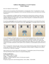
AMPLIFIER SELECTION
Table 1 shows the recommended power amplifier ratings for driving ENTASYS systems. Specifying amplifiers with these
output power ratings will allow the maximum power to be delivered to the loudspeaker when the amplifier is driven to full
output with a signal that has a 6 dB crest factor. For a discussion of crest factor, reference Page 36.
With each ENTASYS enclosure housing sixty-six individual drivers, ENTASYS loudspeaker systems are designed to handle
exceptionally high amplifier power ratings. However, if high SPL is not required for a particular application, a lower powered
amplifier may be used.
WARNING: Amplifiers used should not be overdriven or clipped during operation. Doing so could damage the loudspeaker(s)
it is powering. For more information on amplifiers and limiters, please refer to the ENTASYS Installation/Operation
Manual, Pages 38-39.
If an amplifier is routinely clipping during operation in an attempt to achieve the desired SPL, it should be replaced with an
amplifier with a higher output rating. If an amplifier with a higher output rating would exceed the recommended 3,600 watts
into 4 ohms, it may be necessary to increase the number of loudspeakers to achieve the desired SPL in the audience area of a
venue.
A good method for determining the size of the power amplifier for an application is to do a quick model of the seating and
array location using EASE Focus (reference page 17). Set the Bandwidth to Broadband and the Level to RMS (Max SPL). The
Level View should then display the maximum SPL at the audience ear height. If the SPL in the audience area is much greater
than it needs to be, the size of the power amplifier may be reduced. Alternatively, an amplifier rated at 3,600 watts into 4
ohms may still be used, passing signals with a greater crest factor while providing the average SPL desired. An overview of this
is shown in Table 2.
QUICK START
Full‐Range
Columns
TotalRated
Impedance
(ohm)
Recommended
Power
(watts)
Required
Voltage
(V
RMS
)
AmplifierRating
@8ohm
(watts)
AmplifierRating
@4ohm
(watts)
1 12 600 85 1,800 3,600
2 6 1,200 85‐3,600
3 4 1,800 85‐3,600
Table 1: Recommended Amplifier Size
LowFrequency
Columns
TotalRated
Impedance
(ohm)
Recommended
Power
(watts)
Required
Voltage
(V
RMS
)
AmplifierRating
@8ohm
(watts)
AmplifierRating
@4ohm
(watts)
1 12 600 85 1,800 3,600
2 6 1,200 85‐3,600
3 4 1,800 85‐3,600
LowFrequency
Columns
Full‐Range
Columns
TotalRated
Impedance
(ohm)
Recommended
Power
(watts)
Required
Voltage
(V
RMS
)
AmplifierRating
@4ohm
(watts)
1 1 6 1,200 85 3,600
1 2 4 1,800 85 3,600
2 1 4 1,800 85 3,600

Community ENTASYS Application Guide - Page 17
Using Table 2, locate the SPL reduction value in the column on the left. Any amplifier size in that row can be used. The
heading at the top of that row lists the crest factor of a signal that the amplifier will pass without clipping while still driving
ENTASYS to the desired SPL.
For example, if an EASE (or EASE Focus) model shows that the SPL is 6 dB too high, it can be reduced by employing a smaller
amplifier (e.g., with a 900 W into 4 ohm rating), thereby allowing a signal with only a 6 dB crest factor to yield the desired SPL.
Alternatively, an amplifier rated at 3,600 W into 4 ohms will allow a signal with a 12 dB crest factor to yield the desired SPL.
REQUIRED HIGH PASS FILTER
The use of an external, active high pass filter before the power amplifier(s) driving ENTASYS systems is always required. This
high pass filter will help to protect the woofers from damage due to excessive low frequency excursion. It will also avoid
wasting amplifier power attempting to reproduce frequencies below the loudspeakers’ intended operating range. A high pass
filter set to 200 Hz, 24 dB/octave or higher frequency should always be used. Increasing the high pass filter to a higher
frequency or greater slope will not present any problems for an ENTASYS system.
QUICK START
For6dB
CrestFactor
For9dB
CrestFactor
For12dB
CrestFactor
For15dB
CrestFactor
Reduction
ofSPL
AmplifierRating
(4ohm)
AmplifierRating
(4ohm)
AmplifierRating
(4ohm)
AmplifierRating
(4ohm)
0 3,600
‐3 1,800 3,600
‐6 900 1,800 3,600
‐9 450 900 1,800 3,600
‐12 225 450 900 1,800
‐15 112 225 450 900
‐18 56 112 225 450
‐21 28 56 112 225
‐24 14 28 56 113
‐27 7 14
28 56
‐30 4 7 14 28
Table 2: Amplifier Size Reduction for Decreased SPL and Increased Crest Factor
EASE Focus is a line array software modeling program that may be downloaded without cost from
www.easefocus.com/downloads.html. EASE Focus is an extremely helpful tool for determining how many ENTASYS
modules should be used, where they should be placed, and how they should be aimed to quickly obtain the desired
SPL for an audience area.
For more information on EASE Focus see the System Design Guidelines section on Pages 25-26.

Community ENTASYS Application Guide - Page 18
DIFFERENCES BETWEEN LINE ARRAYS
AND
POINT SOURCE LOUDSPEAKER SYSTEMS
There are several distinct differences between line arrays and point source loudspeakers. Sometimes, point source
loudspeakers are comprised of simply full-range drivers. Many times, they include multiple drivers including combinations of
horns and direct radiating cones that reinforce specific frequency bands. In either case, point source loudspeaker cabinets are
generally built so that all the drivers function as one source. An example of point source type loudspeakers are Community
VERIS and iBOX systems. Much like the behavior of a true acoustical point source, these systems usually have a fairly short
near-field coverage; as the distance from the source increases, their SPL decreases according to the inverse square law.
A line array, on the other hand, is typically very large in one dimension (usually vertical), compared to the wavelength of
frequencies it radiates. This gives it superior directivity control for frequencies with wavelengths greater than twice the length
of the line. Put another way, the length of a line array should be equal to or greater than one-half the wavelength of the lowest
frequency over which directivity control is desired. At frequencies much higher than determined by L = λ/2 (λ = wavelength), a
line array can have a very small coverage angle.
Typically line arrays are oriented vertically. This enables a small vertical coverage angle, or opening angle as it is sometimes
called, to be used to great advantage in reducing reflections and keeping sound off ceilings and other surfaces. This can be very
beneficial in highly reverberant spaces.
In the near-field of a line array, the SPL falls off at -3 dB per doubling of distance, instead of -6 dB as dictated by inverse square
law. Line array systems tend to have a much greater near-field coverage distance than point source systems. This enables a line
array to potentially offer higher SPL at a given distance than a point source system. However, there is a limit to the distance at
which the line array can maintain this -3 dB SPL decrease per doubling of distance. It can only do this in the near-field of the
line array. Beyond the near-field, the SPL from a line array will decrease at -6 dB per doubling of distance.
The near-field can extend very far from a line array, and is dependant on the length of the line array as well as the given
frequency. This means that for a fixed-length line array the near-field distance will change as a function of frequency. Thus the
frequency response of a line array may change depending on the distance away from it.
Another important point to consider is the difference in the size of the origin of radiation for these two types of loudspeakers.
As the name implies, a point source has its origin at a single point. (While this is overly simplistic, it will help to illustrate this
difference.) The sound from a line array, on the other hand, does not originate from a single point, but from a line. While a
point is infinitesimally small and has no physical height, a line does. This difference can play a large role in understanding the
radiation and coverage from a line array.
As an example, consider a point source with a 5 degree vertical coverage angle. At a distance of 30 feet (9.15 m), this point
source will cover a vertical height of approximately 2.6 feet (0.80 m). By comparison, a 3-foot (0.91 m) line array with the
same 5 degree vertical angle will cover a vertical height of approximately 5.6 feet (1.71 m). This sets the origin for its radiation
and will have a bearing on the overall coverage. (This is an extreme example but it does help to demonstrate this fundamental
difference.) For an illustration of this please refer to the ENTASYS Installation/Operation Manual, Pages 49-50.
WHEN TO USE LINE ARRAYS
A line array’s high degree of directivity control makes it particularly well suited for use in highly reverberant spaces, where it is
imperative that sound be directed to the audience areas only and not excite other highly reflective surfaces. This will help to
maximize speech intelligibility in these difficult spaces.
Line arrays also work well in rooms with relatively low ceilings. When the ceiling is low in relation to the depth of the room, it
may not be possible to position a point source system located at the front of the room sufficiently high enough to provide
consistent coverage from the front to the rear-most point in the room. Additional point source loudspeakers would be
required more farther back in the room on a separate “delay” feed. Using a line array system at the front of the room can
make it possible to achieve a consistent SPL distribution from the front to the back of the room, without the need for delay
loudspeakers.
GENERALINFOONLINEARRAYS

Community ENTASYS Application Guide - Page 19
The directivity control of a line array is generally only within the plane of the line. That is, if the drivers in a line array are
arranged vertically (which is most often the case), the directivity control will be in the vertical plane. In the horizontal plane,
directivity will be fairly broad. For this reason, line arrays cannot be rotated on their side and still maintain high vertical
directivity.
PERFORMANCE COMPARISON OF A LINE ARRAY
AND
POINT SOURCE SYSTEM IN THE SAME ROOM
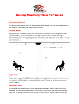
Perhaps one of the best ways to understand the differences between a line array and a point source system is to design a
system for the same room using each type of system and compare them. It would be prohibitively costly to actually execute,
install, and evaluate each system in this manner, however this comparison can be carried out virtually using acoustical
computer modeling. Two designs were prepared and modeled in the same room using EASE 4.2. The example used was a
small house of worship with a 2.0 - 2.5 second reverb time.
The ENTASYS line array system is shown in Figure 13. This system uses columns of two stacked ENTASYS Full-Range
loudspeakers on each side at the front of the main seating area. One additional ENTASYS Full-Range loudspeaker is flown to
provide coverage to the balcony area.
By comparison, Figure 14 shows a point source system in the same space. This system uses a main cluster of two Community
SLS960 and two SLS915 loudspeakers covering the floor area. Three SLS915 loudspeakers are used on a delay to provide
coverage to the balcony area.
Note that on the SLS center cluster design, a high mounting position was necessary to preserve sightlines for the religious
symbols. If those sightlines were not a consideration, the array could be lower and the intelligibility would be higher for the
front of the audience especially. Sightlines of this nature are a common important consideration to the loudspeaker design.
The sightline issue is completely avoided by using the ENTASYS system design.
The direct SPL on the room surfaces is shown in Figures 15 - 22. The odd number figures reflect the ENTASYS system,
while the even numbers illustrate the point source system.
The SPL maps confirm that both systems provide good coverage to the audience areas, averaging approximately 95 dB SPL for
the direct field. However, the point source system maintains this SPL slightly better from the front to the back of the room
due to its high elevation.
The potential intelligibility of each system is compared in the graph shown in Figure 23. This shows C50 for each system in
this room. C50 is a measure of the clarity and correlates well with intelligibility. (Higher values indicate greater clarity and
potential intelligibility.) The ENTASYS system offers, on average, about 2 - 3 dB greater clarity below 5 kHz than the point
source system, indicating greater potential intelligibility. This is further confirmed by the predicted %Alcons (percentage
articulation loss of consonants) of 13.3% for the point source system and 10.6% for the ENTASYS system.
It should also be noted that the point source system design delivers considerably higher SPL to the altar area (Figure 16 &
Figure 18) than the ENTASYS system design (Figure 15 & Figure 17). This would confirm the ENTASYS system’s potential
for considerably higher gain before feedback – another distinct advantage.
From a cost perspective, the point source system utilizes seven loudspeakers (all requiring rigging to be flown), four channels
of amplification, and a signal delay unit. The ENTASYS system employs just five loudspeakers (only one requiring rigging), three
channels of amplification, and a signal delay unit. While the loudspeakers used in the point source system are physically larger
and capable of reproducing some lower frequencies that the ENTASYS systems will not, adding a VLF208 dual 8-inch
subwoofer below each ENTASYS on the front wall would deliver comparable low frequency output, while still coming in at or
below the cost of the point source system.
GENERALINFOONLINEARRAYS

Community ENTASYS Application Guide - Page 20
GENERALINFOONLINEARRAYS
Figure 14: House of Worship with Point Source Loudspeaker System
Figure 13: House of Worship with ENTASYS Systems
/