
CX462
Installation & Setup
Guide
Version 3
CX462 AUDIO SYSTEM CONTROLLER
Cloud Electronics Limited
Copyright Cloud Electronics Limited 2004
‘Clearly Better Sound’


CLOUD ELECTRONICS LIMITED
CX462 Installation and Setup Guide
©
Cloud Electronics Limited
140 Staniforth Road • Sheffield S9 3HF • England
Phone +44 (0)114 244 7051 • Fax +44 (0)114 242 5462
E-mail [email protected] • WebSite www.cloud.co.uk


CLOUD ELECTRONICS LIMITED
Table of Contents
Section Page
CX462 Audio System Controller Setup And Installation Guide
1 Safety Notes . . . . . . . . . . . . . . . . . . . . . . . . . . . . . . . . . . . . . . . . . . .1
2 General Description . . . . . . . . . . . . . . . . . . . . . . . . . . . . . . . . . . . . .1
3 Schematic Diagram . . . . . . . . . . . . . . . . . . . . . . . . . . . . . . . . . . . . .2
4 Installation . . . . . . . . . . . . . . . . . . . . . . . . . . . . . . . . . . . . . . . . . . . .2
5 Stereo/Music Inputs . . . . . . . . . . . . . . . . . . . . . . . . . . . . . . . . . . . . .2
5.1 Sensitivity and Gain Control . . . . . . . . . . . . . . . . . . . . . . . . . . . .2
5.2 Music control - Local or Remote . . . . . . . . . . . . . . . . . . . . . . . . .3
5.3 Music Equalisation . . . . . . . . . . . . . . . . . . . . . . . . . . . . . . . . . . . .4
5.4 Line 6 Priority . . . . . . . . . . . . . . . . . . . . . . . . . . . . . . . . . . . . . . . .4
6 Microphone Inputs . . . . . . . . . . . . . . . . . . . . . . . . . . . . . . . . . . . . . . .5
6.1 Microphone Access Contacts . . . . . . . . . . . . . . . . . . . . . . . . . . . .6
6.2 Microphone Gain Controls . . . . . . . . . . . . . . . . . . . . . . . . . . . . . .6
6.3 Microphone Level Controls . . . . . . . . . . . . . . . . . . . . . . . . . . . . .7
6.4 Microphone Equalisation . . . . . . . . . . . . . . . . . . . . . . . . . . . . . . .7
6.5 High Pass Filter . . . . . . . . . . . . . . . . . . . . . . . . . . . . . . . . . . . . . . .7
6.6 Microphone 1 Priority . . . . . . . . . . . . . . . . . . . . . . . . . . . . . . . . . .8
6.7 Microphone over Music priority . . . . . . . . . . . . . . . . . . . . . . . . . .8
7 Output Details . . . . . . . . . . . . . . . . . . . . . . . . . . . . . . . . . . . . . . . . . . .9
8 Active Modules - General Specification . . . . . . . . . . . . . . . . . . . . . . . .9
8.1 Active Equalisation Modules . . . . . . . . . . . . . . . . . . . . . . . . . . . .10
8.2 Cloud CDI-S100 Serial Interface Module . . . . . . . . . . . . . . . . . .11
9 Remote Music Mute - Fire Alarm interface . . . . . . . . . . . . . . . . . . . .12
10 Technical Specifications . . . . . . . . . . . . . . . . . . . . . . . . . . . . . . . . . .12
11 General Specifications . . . . . . . . . . . . . . . . . . . . . . . . . . . . . . . . . . .13

CLOUD ELECTRONICS LIMITED
Table of Contents
Section Page
CX462 Audio System Controller Setup And Installation Guide
12 Troubleshooting . . . . . . . . . . . . . . . . . . . . . . . . . . . . . . . . . . . . . . . .13
12.1 Ground/Earth Loops . . . . . . . . . . . . . . . . . . . . . . . . . . . . . . . . .13
12.2 Connecting balanced signals to unbalanced line inputs . . . . . .13
12.3 Cloud CDI-S100 Serial interface is not working properly . . . .14
12.4 Microphone access switches not working correctly . . . . . . . . . .15

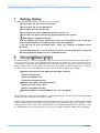
1 Safety Notes
For more detailed information refer to the rear of the manual.
w
Do not expose the unit to water or moisture.
w
Do not expose the unit to naked flames.
w
Do not block or restrict any air vent.
w
Do not operate the unit in ambient temperatures above 35°C.
w
Do not touch any part or terminal carrying the hazardous live symbol
( ) while power is supplied to the unit.
w
Do not perform any internal adjustments unless you are qualified to do so and fully
understand the hazards associated with mains operated equipment.
w
The unit has no user serviceable parts. Refer any servicing to qualified service
personnel.
w
If the moulded plug is cut off the lead for any reason, the discarded plug is a potential
hazard and should be disposed of in a responsible manner.
2 General Description
The Cloud CX462 is a versatile, microphone and line input mixer. The mixer has a music section with six
stereo line inputs. A source select control routes the desired line input to the stereo music outputs. It has
a microphone section with four microphone inputs that are mixed and sent to the separate, mono mic
output. In order to increase the mixers versatility there are controls to add the output of one section to
the other. There are various optional accessories that extend the flexibility of the CX462:
w
Optional serial interface card (CDI-S100) that allows control of:
s
Music level and source
s
Master microphone level
s
Individual microphone mutes
w
Optional remote plates that allow control of
s
Music level and source. RSL-6
s
Master microphone level RL-1
w
Equalisation Modules for Bose® Model 8, 25, 32 & 102 Speakers.
Along with these accessories the CX462 has: - Microphone priorities, Fire alarm mute and the possibility
for Line 6 to have priority over other music signals.
Controls for the CX462 are provided on either the front or the rear of the product. Controls which should
only be configured when the product is being installed are located on the rear panel; controls used to
change the level, music source, tone or prioritisation in the CX462 are located on the front panel. Once
the tamperproof facia is in place, only the level, source selection and power controls will be available.
CX462 Audio System Controller Setup And Installation Guide
CLOUD ELECTRONICS LIMITED
1 V3 280904

CX462 Audio System Controller Setup And Installation Guide
CLOUD ELECTRONICS LIMITED
2V3 280904
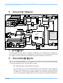
3 Schematic Diagram
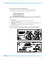
4 Installation
The Cloud CX462 occupies one unit of standard 19” equipment rack. Front panel pre-set controls can
be covered with the cover provided. Ventilation holes on the base of the unit should not be obscured.
The CX462 is 152.5mm deep but a depth of 200mm should be allowed to clear connectors.
5 Stereo/Music Inputs
The music section of the CX462 has six stereo inputs. These line inputs are suitable for most music
sources such as compact disc players, tape players and receivers etc.. All inputs are unbalanced and
use RCA type phono connectors. Input impedance is 48kΩ.
5.1 Sensitivity and Gain Control
All six line inputs have pre-set gain controls which are accessible on the rear panel, adjacent
to their respective input sockets. The input sensitivity can be varied from -17.6dBu (100mV) to
+ 5.7dBu (1.5V). The pre-set gain controls should be set so that all the input signals operate
at the same level within the CX462 and the music level controls have an optimum control range.
GAIN
LINE1
LINE2
LINE3
LINE4
LINE5
LINE6
L
R
STEREOSIGNALPATHSHOWSLEFTCHANNELONLY
EQ
GAIN
MIC4
MIC3
MIC2
ON
OFF
EQ
GAIN
MIC1INPUT
ON
OFF
GATE
PHANTOMPOWER
PRIORITY
OFF
SW
LINE6
PRIORITY
RELEASE
TIME
3s6s
150Hz
PARAMETRIC
EQUALISER
MICACCESS
ACC
AVO
VCA
FREQ
GAIN
MIC
LEVEL
SERIALINTERFACE
OPTIONAL
SPEAKER
MODULE
PHANTOMPOWER
MUSIC
EQ
MUSIC
VCA
1
2
3
PRIORITY
VOLTAGE
CONTROLLED
SOURCESELECT
OPTIONALMUSIC
SOURCEANDLEVEL
REMOTECONTROL
OPTIONALMIC
LEVELREMOTE
CONTROL
MUSICOUT
MICOUT
J16
MUTE
MUTE
MUTE
MIC2:J19
MIC3:J5
MIC4:J6
J18
MIC
TO
MUSIC
ADDITIONALJUMPERS
J1-4:MICACCESSBYPASS
J7:FORCEANALOGUE
MUSICSOURCESELECT
J8:FORCEANALOGUE
MUSICLEVELCONTROL
J9:FORCEFRONTPANEL
MUSICSOURCESELECT
J10:FORCEFRONTPANEL
MUSICLEVELCONTROL
J13:MUSICMUTENORMALLY
CLOSED/OPEN
J11
J12
J17
MUSIC
TO
MIC
SPEAKER
MODULE
1
2
3
OFFON
FROMRIGHTCHANNEL
MONO
STEREO
J14
12s:NOJUMPER
POST
PRE
J15

CX462 Audio System Controller Setup And Installation Guide
CLOUD ELECTRONICS LIMITED
3 V3 280904
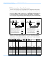
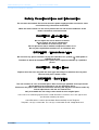
5.2 Music control - Local or Remote
The music source and music level control functions can be controlled from either the front
panel or a remote control plate located up to 100m from the CX462. There are two remote
control plates available for the CX462, the RSL-6 and the RL-1. The RSL-6 should be used
when remote control of music source and music level is required whereas the RL-1 can be
used when the application calls for remote control of the level only (source selection via front
panel). RSL-6 and RL-1 remote control plates can be mounted onto a standard British flush
or surface mounted 25mm deep back box. Two-core cable with overall screen should be
used to connect the remote controls to the Cloud CX462 and the diagrams below show how
to connect the two remote plates. Self-adhesive labels (supplied) can be affixed to the front
panel and/or RSL-6 to identify the available input sources.
For remote operation of music level (RL-1) or level and source select (RSL-6), the front panel
switch must be set to the ‘REMOTE’ position. The rear panel switch marked ‘REMOTE
TYPE’ should be set to the ‘ANALOGUE’ position. Jumpers J7-J10 determine whether the
control of the music controls is determined by the rear panel switch. A table containing the
possible configurations and their effects is detailed below.
STANDARDWIRINGCONVENTION
USETWOCORESCREENEDCABLE
FRONTPANELSWITCHSHOULDBE
SETTOTHE‘REMOTE’POSITION
REARPANELSWITCHSHOULDBE
SETTOTHE‘ANALOGUE’POSITION
REMOTECONTROLOFMUSICLEVEL
FRONTSWITCH
REMOTE(IN)
REARSWITCH
ANALOGUE(OUT)
1 2 3
3POLE
CONNECTOR
1 2 3
RL-1
STANDARDWIRINGCONVENTION
USETWOCORESCREENEDCABLE
FRONTPANELSWITCHSHOULDBE
SETTOTHE‘REMOTE’POSITION
REARPANELSWITCHSHOULDBE
SETTOTHE‘ANALOGUE’POSITION
REMOTECONTROLOFMUSIC
FRONTSWITCH
REMOTE(IN)
REARSWITCH
ANALOGUE(OUT)
1 2 3
3POLE
CONNECTOR
1 2 3
RSL-6
FRONT/SWITCH AN/SW
FRONT
SWITCH
REAR
SWITCH
LEVEL
SOURCE
SELECT
J9 J10 J7 J8
N/A N/A N/A N/A ‘LOCAL’ N/A FRONT FRONT
‘FR’ ‘FR’ N/A N/A N/A N/A FRONT FRONT
‘SW’ ‘SW’ ‘SW’ ‘SW’ ‘REMOTE’ ‘ANALOGUE’ RSL-6 RSL-6
‘SW’ ‘SW’ ‘SW’ ‘SW’ ‘REMOTE’ ‘DIGITAL’ CDI-S100 CDI-S100
‘SW’ ‘FR’ ‘SW’ N/A ‘REMOTE’ ‘ANALOGUE’ FRONT RSL-6
‘SW’ ‘FR’ ‘SW’ N/A ‘REMOTE’ ‘DIGITAL’ FRONT CDI-S100
‘FR’ ‘SW’ N/A ‘SW’ ‘REMOTE’ ‘ANALOGUE’ RSL-6/RL-1 FRONT
‘FR’ ‘SW’ N/A ‘SW’ ‘REMOTE’ ‘DIGITAL’ CDI-S100 FRONT
‘SW’ ‘SW’ N/A N/A ‘REMOTE’ ‘ANALOGUE’ RSL-6 RSL-6
‘SW’ ‘SW’ ‘AN’ ‘AN’ ‘REMOTE’ N/A RSL-6 RSL-6
‘SW’ ‘SW’ ‘AN’ ‘SW’ ‘REMOTE’ ‘DIGITAL’ CDI-S100 RSL-6
‘SW’ ‘SW’ ‘SW’ ‘AN’ ‘REMOTE’ ‘DIGITAL’ RSL-6/RL-1 CDI-S100

CX462 Audio System Controller Setup And Installation Guide
CLOUD ELECTRONICS LIMITED
4V3 280904
The RSL-6A and RL-1A are available for the American market. They have identical operation
to the RSL-6 and RL-1 but have been designed to fit a single gang US electrical outlet box.
Front panel dimensions are 4½” x 2¾”.
When setting the jumper(s) please ensure that you:
w
Remove the mains cable from the rear of the product before removing the top
panel.
w
Only reassemble the unit using screws identical to the original parts.
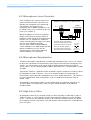
5.3 Music Equalisation
Front panel pre-set controls for treble and bass equalisation of the music signals are provided
in order to allow the installer to tailor the response of the music signals to suit the acoustics
and speaker’s response. The equalisation controls can be concealed behind the removable
plate secured to the front panel with hex key screws; to gain access to the equalisation
controls use the supplied hex key. The equalisation controls are located to the left of the
music source and level controls; they are clearly marked ‘HF’ (High Frequency) and ‘LF’ (Low
Frequency). A flat frequency response can be achieved by positioning the slots on the
control shafts in the vertical plane; the HF control has a range of ±10dB at 10kHz and the LF
control has a range of ±10dB at 50Hz.
5.4 Line 6 Priority
The line 6 music input can be given priority over other music signals. This is intended for use
with sources such as jukeboxes or spot announcement players. This priority is triggered
when a signal is detected on the line 6 input, at which point the selected music source will
mute and the line 6 signal is routed to the output. Once the signal on line 6 ceases, the
selected music source will smoothly restore to its former level. The time taken for this
restoration can be 3, 6 or 12 seconds dependant on how internal jumper J12 has been set;
the factory default restoration time is 3 seconds. In order to switch priority on or off, the
internal jumper J11 can be set, both jumpers a and b will need to be set in the same position.
When setting the jumper(s) please ensure that you:
w
Remove the mains cable from the rear of the product before removing the top
panel.
w
Only reassemble the unit using screws identical to the original parts.
Music Control continued
Remote control enabling
jumpers
J9: Music source
J10: Music level
Location of Jumpers J9 & J10

CX462 Audio System Controller Setup And Installation Guide
CLOUD ELECTRONICS LIMITED
5 V3 280904
Line 6 Priority continued
6 Microphone Inputs
Four microphone inputs are provided each having electronically balanced, transformer-less circuitry
configured for optimum low noise performance. The input impedance is greater than 2kΩ and suitable for
microphones in the 200Ω to 600Ω range. Inputs are via 3-pin plug in screw terminal type connectors
(Phoenix type) located on the rear panel. A facility to provide 15V phantom power is included for each
microphone that is activated by setting the relevant internal jumpers from the list below to the ‘ON’
position:
NOTE: Microphones one and two have their jumpers located on the upper microphone input circuit
board.
When setting the jumper(s) please ensure that you:
w
Remove the mains cable from the rear of the product before removing the top panel.
w
Only reassemble the unit using screws identical to the original parts.
All microphone inputs are balanced with the following pin configuration:
w
Pin 1 - GROUND
w
Pin 2 - COLD/INVERTING
w
Pin 3 - HOT/NON-INVERTING
To connect an unbalanced microphone to the input, use pins 1 and 3 with pin 2 connected to ground
(Pin 1).
J18: Mic 1 phantom power
J19: Mic 2 phantom power
J5: Mic 3 phantom power
J6: Mic 4 phantom power
Location of Jumpers J5 & J6
Location of Jumpers J11 & J12
Line 6 Priority Jumpers
J11: Priority on/off
J12: Release time 3s
6s
12s

CX462 Audio System Controller Setup And Installation Guide
CLOUD ELECTRONICS LIMITED
6V3 280904
6.1 Microphone Access Contacts
Access contacts for each individual microphone input are provided on the rear panel. Individual
microphone inputs can be activated by connecting their respective contact to the 0V contact,
leaving the access terminal open circuit will mute the microphone input. This provides the
facility to mute microphones using remote switches. When these access contacts are not
required they can be bypassed via the configuration of the internal jumpers detailed below:
NOTE: We advise that when you remove a jumper you leave it connected to one pin of the
header so it remains with the apparatus for future use.
The default factory configuration of these jumpers is to bypass access terminals, leaving all
microphone inputs active. It is also possible to mute the microphone inputs using the CDI-S100
interface module. In order for the CDI-S100 to effectively mute a microphone channel, the
corresponding jumper must be in place.
When setting the jumper(s) please ensure that you:
w
Remove the mains cable from the rear of the product before removing the top
panel.
w
Only reassemble the unit using screws identical to the original parts.
6.2 Microphone Gain Controls
Pre-set gain controls are provided adjacent to the respective microphone input. The gain can
be adjusted from 0dB to 60dB. Typically, a setting of ~30dB is adequate for dynamic
microphones. A high overload margin is maintained at all gain settings. This should allow a
signal range from 0.775mV (-60dBu) to 775mV (0dBu).
Access bypass jumpers
J1- 4: Microphones 1- 4 respectively
Location of Jumpers J1- 4

CX462 Audio System Controller Setup And Installation Guide
CLOUD ELECTRONICS LIMITED
7 V3 280904
6.3 Microphone Level Controls
Each microphone has separate front panel
mounted controls for their respective level.
Rotating any microphone level control fully
anti-clockwise effectively turns the
microphone off. In addition microphones can
be muted via the access contacts on the rear
panel (see section 6.1)
Master microphone level can be controlled
locally via the front panel rotary control, or
through a remote wall plate up to 100m away
from the unit. To configure the CX462 for
remote level operation, the front panel switch
must be in the 'REMOTE' position.
The rear panel switch marked 'REMOTE
TYPE' should be in the 'ANALOGUE' position.
Master microphone level can also be
controlled via the Cloud CDI-S100 Serial
Interface Module (see section 8.2).
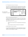
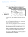
6.4 Microphone Equalisation
Two-band equalisation is provided for each individual microphone input. The pre-set controls
to adjust the equalisation are located to the upper-right of each front panel microphone level
control. The characteristics of the equalisation are optimised for the tonal correction of
speech signals. The HF control provides ±10dB at 5kHz whilst the LF control provides ±10dB
at 150Hz.
A parametric equaliser is applied to all the microphone signals, to allow the installer to correct
for microphone or room resonance. The pre-set controls to adjust the equalisation are
located to the upper-right of the microphone master level control (front panel). This equaliser
has been optimised for vocals and provides a gain of ±10dB over a frequency range of
300Hz - 3kHz.
All microphone equalisation controls are concealed behind the removable front panel. To
effectively bypass an equalisation section, the gain control should be set to 0dB (mid-
position/vertical).
6.5 High Pass Filter
All microphone channels pass through a high pass filter operating at 150Hz with a slope of
18dB per octave; as such it provides effective attenuation of breath blasts and LF handling
noises. This filter can be switched in or out via the front-panel switch located to the right of
the microphone master level control. This switch will be concealed when the removable front
panel is in place.
STANDARDWIRINGCONVENTION
USETWOCORESCREENEDCABLE
FRONTPANELSWITCHSHOULDBE
SETTOTHE‘REMOTE’POSITION
REARPANELSWITCHSHOULDBE
SETTOTHE‘ANALOGUE’POSITION
REMOTECONTROLOFMICLEVEL
FRONTSWITCH
REMOTE(IN)
REARSWITCH
ANALOGUE(OUT)
1 2 3
3POLE
CONNECTOR
1 2 3
RL-1

CX462 Audio System Controller Setup And Installation Guide
CLOUD ELECTRONICS LIMITED
8V3 280904
6.6 Microphone 1 Priority
Microphone 1 can be given priority over microphones 2-4. This feature can be triggered in
two ways, selected through the position of internal jumper J17:
w
‘AVO’: priority is given when a signal is detected on the mic 1 input.
w
‘ACC’: priority is given when mic 1 access is selected via the microphone
access contacts on the rear panel.
Note that J17 should only be set to access triggered priority if you intend to use the MIC 1
rear panel access contact. Priority is switched in or out via the front panel switch marked
'MIC 1 OVER MICS'. All priority controls are concealed when the removable front panel is
attached.
6.7 Microphone over Music priority
The CX462 provides a facility whereby microphone signals can be given priority over music
signals. When a signal is detected on any of the mic inputs, all music signals are attenuated
to a level determined by the front panel attenuation control. Once there is no microphone
signal present, the music will restore to the previous settings.
The priority circuitry can be set to detect the presence of a mic signal either before or after
the "Add Mic" front panel rotary control by setting internal jumper J15 to PRE or POST. If the
priority circuitry is set before this control(PRE), then the music signals will attenuate
regardless of whether any microphone signal is fed through to the stereo music output. If the
priority circuitry is set after this control (POST) then the music signals will attenuate only if
some mic signal is fed into the music output. Note that regardless of this jumper setting the
priority circuitry will attenuate the music level in both mic and music outputs.
Microphone 1 can be configured to take priority via the access contacts on the rear panel,
rather than voice detected triggering. To permit this, internal jumper J16 must be set to the
'ACCESS' position (see above diagram for location of J16). Note that J16 should only be set
to the ‘ACCESS’ position if you intend to use the Mic 1 rear panel access contact (see
section 6.1).
The degree to which music signals are attenuated can be set via the front panel attenuation
control, which ranges from -10dB to -60dB. Setting the front panel switch marked 'MIC OVER
MUSIC' to the 'OFF' position will defeat the Microphone priority circuit. All priority controls
are concealed when the removable front panel is attached.
Microphone 1 priority jumpers
J16: Mic 1 over music
signal/access triggered.
J17: Mic1 over mics
signal/access triggered
Location of Jumpers J16 & J17

CX462 Audio System Controller Setup And Installation Guide
CLOUD ELECTRONICS LIMITED
9 V3 280904
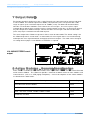
7 Output Details
Each output terminal is balanced, using a 3 pole 'Phoenix' type connector and can operate into loads
as low as 600Ω. The nominal output level is 0dBu (775mV) but the mixer can operate with a wide
range of signals up to a maximum output level of +20dBu (7.75V). For balanced interconnections,
two-core screened cable should be used. Connect the screen to pin 1, the reverse phase signal
(normally blue or black) to pin 2 and the in-phase signal (normally red) to pin 3. If you wish to connect
any zone output to an unbalanced input, connect the cable screen to pin 1 with the hot connection
(inner core) to pin 3 and make no connection to pin 2.
The music output of the CX462 can operate in either stereo or mono mode. The default setting is for
the CX462 to operate in stereo mode. In mono mode, all stereo signal sources are mixed internally
and output the same signal to both left and right channel music outputs. The mode can be changed
via setting internal jumper J14 to 'MONO' or 'STEREO' as required.
8 Active Modules - General Specification
Active modules available for the CX462 include Acive Equalisation modules and the Cloud CDI-S100
Serial Interface Module. The CX462 can provide a maximum of 80mA current to active modules and
external devices (such as a CPM paging microphone). Current consumptions of the various modules
are detailed in the table below:
J14: MONO/STEREO music
output
Location of Jumper J14
Module Description Current Required
CDI-S100 Serial Interface Module 35mA
BOSE
®
EQ cards: M8, M32, MA12, 402, 502A, 802, MB4, MB24, 502B, 502BEX
12mA
BOSE
®
EQ cards: LT3302, LT4402, LT9402, LT9702
17mA
BOSE
®
EQ card M16
24mA

CX462 Audio System Controller Setup And Installation Guide
CLOUD ELECTRONICS LIMITED
8.1 Active Equalisation Modules
Each output channel has the facility to connect a plug-in equalisation module.
The internal equalisation module connectors are marked on the main PCB as:
w
CON3 for Right Music output
w
CON4 for Left Music output
w
CON5 for Microphone output.
When the music output is set for mono, using Jumper J14, only one EQ card is required. The
card may be fitted to either CON3 or CON4 depending on the output socket you choose to
use.
Installation:
1. Switch off the mains supply and remove the CX462's power lead.
2. Remove the unit's top panel
3. Fit the EQ module to the connector. The EQ card board should be perpendicular to the
main board.
4. Apply moderate pressure to the EQ card until it locates with a click.
5. Replace the top panel.
NOTE: In mono mode (see section 7), it is possible to use a mono equalization module on
only one of the channels, giving one channel with the equalized signal and one without.
10
V3 280904
Location of Equalisation Module Connector CON5
Location of Equalisation Module Connectors CON3 and CON4

CX462 Audio System Controller Setup And Installation Guide
CLOUD ELECTRONICS LIMITED
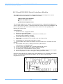
8.2 Cloud CDI-S100 Serial Interface Module
The CX462 can be used as part of an automated sound system through the use of the
CDI-S100 Serial Interface Module. The module can control:
w
Music source, level and mute
w
Master microphone level
w
Individual microphone mutes
The CDI-S100 module music controls can be defeated via the setting of internal jumpers J7
(source select) and J8 (volume). Setting the front panel switch marked 'LOCAL/REMOTE' to
the 'LOCAL' position will defeat remote control of the CX462. The corresponding LED
indicates the current state.
Installation:
1. Disconnect mains supply from CX462.
2. Remove top panel from CX462.
3. Remove the panel that blocks the serial interface terminal space
when no interface module is installed.
4. Locate connector CON7 (16 pin ribbon)
5. Remove M3 screw behind CON7 and M3 screw left of C96. Keep
to one side.
6. Screw 25mm hex spacers into screw holes in step 5.
7. Connect ribbon cable attached to module to CON7 terminal. Pin 1 should be the front
right pin.
8. Place module over spacers, making sure to line up the interface
socket with the corresponding hole.
9. Use M3 screws, saved from step 3, to firmly affix board to spacers.
10. Set rear panel 'REMOTE TYPE' switch to 'DIGITAL' position.
11. Set front panel 'LOCAL/REMOTE' switch to remote.
12. Check and set internal jumpers J7-10 to configure the module’s effect on music signals.
13. Ensure that jumpers J1-4 are in the bypass setting (connection made).
Details on how to operate the CX462 via the CDI-S100 interface are provided in the module
manual. The manual will arrive with the module, but can also be requested from
[email protected] if lost.
11
V3 280904
Location of CDI-S100 Serial Interface Module Connector CON7

CX462 Audio System Controller Setup And Installation Guide
CLOUD ELECTRONICS LIMITED
9 Remote Music Mute - Fire Alarm interface
In certain installations, such as licensed premises or retail outlets within a shopping mall, there may be
a local authority or fire service requirement to mute the music signals via a fire alarm control panel in
an alarm condition. The CX462 provides a facility to mute the music signals only, by using a fully
isolated pair of contacts. This is usually a relay mounted close to the CX462, which is powered by the
fire alarm control panel. The relay can either be closed or opened in an alarm condition, but the
internal jumper J13 MUST be set to the corresponding position:
w
N/C: Alarm condition when the relay opens.
w
N/O: Alarm condition when the relay closes.
When setting the jumper(s) please ensure that you:
• Remove the mains cable from the rear of the product before removing the top panel.
• Only reassemble the unit using screws identical to the original parts.
10 Technical Specifications
Line Inputs
Microphone Inputs
12V3 280904
Frequency Response 20Hz-20kHz +0, -0.5dB
Distortion <0.03% 80kHz Bandwidth
Sensitivity 100mV (-17.8dBu) to 1.5V (+5.7dBu)
Input Gain Control 24dB range
Input Impedance
48kΩ
Headroom >20dB
Noise -91dB rms 22kHz Bandwidth (0dB gain)
Equalisation HF: ±10dB/10kHz, LF: ±10dB/50Hz
Frequency Response
-3dB@ 30Hz (without filter)
20kHz -0.5dB, +0dB
-3dB@ 150Hz (with filter)
Distortion <0.05% 20kHz Bandwidth
Gain Range 0dB-60dB
Input Impedance
>2kΩ(balanced)
Common mode rejection >70dB 1kHz Typical
Headroom >20dB
Noise -128dB rms EIN 22kHz Bandwidth
Equalisation HF: ±10dB/5kHz LF: ±10dB/150Hz

CX462 Audio System Controller Setup And Installation Guide
CLOUD ELECTRONICS LIMITED
Outputs
1
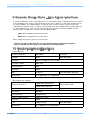
1 General Specifications
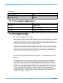
12 Troubleshooting
12.1 Ground/Earth Loops
Despite your best efforts, if the completed sound system 'hums' you probably have a 'ground
loop'; the offending signal source can be found by setting the volume control to minimum then
disconnecting the input leads (both left & right channels) on each line input until the 'hum'
disappears. This problem is often caused by terminating a screened input cable into a signal
source positioned a significant distance from the CX462.
A good way of avoiding this potential problem is to use signal sources (CD players and the
like) that are double insulated with no connection to the mains supply earth. If a signal feed is
derived from a second device (a club or microphone mixer for example) it would be perfectly
normal to expect this to be earthed; we suggest that a transformer be used to isolate the
signal and prevent a noisy loop (see diagrams below)
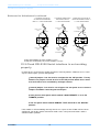
12.2 Connecting balanced signals to unbalanced line
inputs
We recommend the use of a transformer to convert a balanced signal to an unbalanced
signal suitable for direct connection to the CX462 line inputs. The transformer should be
mounted close to the CX462 and the unbalanced output lead should be kept as short as
possible. Where both the source and destination units are earthed, it is important to isolate
the primary and secondary windings to avoid a potential ground loop; if there is any doubt
about this, we suggest that the balanced cable screen is not connected at the transformer
end. RS Components part 210-6447 is a suitable transformer for this application we
recommend that the screening can (part number 210-6469) also be fitted to the transformer;
Canford Audio supplies a similar transformer (part number OEP Z1604). All transformers
should be wired to give a ratio of 1:1.
13
V3 280904
Nominal output level 0dBu
Minimum load impedance
600Ω
Maximum output level +20dBu
Power Input 230V/115V ±10%
Fuse Rating T100mA 230V
T200mA 115V
Fuse Type 20mm x 5mm 250V
Dimensions 482.60mm x 44.00mm(1U) x 152.5mm
Weight(kg) 2.5

CX462 Audio System Controller Setup And Installation Guide
CLOUD ELECTRONICS LIMITED
14V3 280904
12.3 Cloud CDI-S100 Serial interface is not working
properly
In order for the serial interface module to interface correctly with the CX462, there are some
aspects which require specific configuration.
w
Internal jumpers J7 & J10 must be configured to the 'SW' position. Factory
default is for jumpers J7 and J8 to be in the 'AN' position which forces music
level and source to be controlled by analogue remotes.
w
Internal jumpers J1-4 must be set to bypass the rear panel access contacts.
Jumpers should be connecting the header pins.
w
Verify that the front panel switch marked 'LOCAL/REMOTE' is set to the
'REMOTE' position.
w
The rear panel switch marked 'REMOTE TYPE' should be in the 'DIGITAL'
position.
If the module is still not working correctly once these aspects of the CX462 unit have been
configured, consult the module manual for details of the serial port connections and the
communications protocol.
Balanced to Unbalanced continued
AUDIO TRANSFORMER RS PART NUMBER: 210-6447
FITTED WITH SCREENING CAN RS PART NUMBER: 210-6469
SINGLESCREEN
CABLE
SINGLESCREEN
CABLE
HOT
SCREEN
HOT
SCREEN
HOT
SCREEN
HOT
COLD
TWO-CORE
SCREENED
CABLE
(SCREENNOTCONNECTED
ATTHISEND)
HOT
HOT
COLD
TWO-CORE
SCREENED
CABLE
TWO-CORE
SCREENED
CABLE
(SCREENNOTCONNECTED
ATTHISEND)
SINGLESCREEN
CABLE
COLD
SCREEN
CONVERTINGUNBALANCED
TOBALANCEDUSINGA
1:1RATIOTRANSFORMER
CONVERTINGTWOPIECES
OFUNBALANCEDEQUIPMENT
USINGA1:1RATIOTRANSFORMER
CONNECTINGTWOPIECESOF
BALANCEDEQUIPMENTUSINGA
1:1RATIOTRANSFORMER
Page is loading ...
Page is loading ...
Page is loading ...
-
 1
1
-
 2
2
-
 3
3
-
 4
4
-
 5
5
-
 6
6
-
 7
7
-
 8
8
-
 9
9
-
 10
10
-
 11
11
-
 12
12
-
 13
13
-
 14
14
-
 15
15
-
 16
16
-
 17
17
-
 18
18
-
 19
19
-
 20
20
-
 21
21
-
 22
22
-
 23
23


Ask a question and I''ll find the answer in the document
Finding information in a document is now easier with AI
Related papers
Other documents
-
 K-TOUCH S100 User manual
-
Bose Aviation Headset X Installation guide
-
NAD Silver S100 User manual
-
EPH Controls RFC Installation guide
-
EPH Controls RFCA Installation guide
-
EPH Controls 20221108 User manual
-
 Event electronic S100 User manual
-
Niles LZR800 User manual
-
Pulse ACTIVE PRO Series Quick start guide
-
Bogen DMP-06 User manual

