
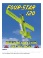
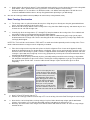
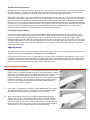
Introduction
First, some history. In June of 1989, SIG Mfg. introduced the FourStar 40 to the modeling world. No, it wasn't an overnight
success, but its reputation quickly spread. Novice flyers suddenly looked like pros and experts couldn't believe how slow it could
land without stalling. Instructors began calling us with stories about training people to fly R/C with the FourStar 40, even though
it's never been promoted as a trainer. Clubs even began using it for one-design pylon races!

.
Modelers were also amazed at how fast and easy it was to build. A couple of weeks
of spare time was sufficient for most builders. We've heard from people who can
frame one up in twelve, ten, even six hours. Another group of modelers actually built
and flew a Four-Star 40 in a day! The design has become so popular in some clubs
that it's practically the official "club plane".
It became fairly obvious that the Four-Star 40 was like a good movie it deserved a
sequel. The reason that it was enlarged to a 1.20-sized airplane was simple - that's
what we wanted for ourselves, so that's what we built! Besides, large sport models
have become very popular the last few years and SIG needed an airplane that could
introduce sport modelers to the world of "big birds". With its 81" wing span, the Four-
Star 120 is big enough to qualify for I.M.A.A. fly
-
ins, but is still fairly easy to transport.
The Four-Star 120 isn't a simple blow-up of the "40"-size. Some elements of aircraft design don't conform well to enlargement.
For instance, the engines for this design are proportionally heavier than those for the smaller Four-Star, which meant a shorter
nose moment was necessary for the "120". In effect, the "120" is an entirely new design, but it still incorporates the aerodynamic
and structural features that made the Four-Star 40 such a success. What are they? There's no secret to it, really - the simple
answer is "lightness and wing area".
The two main goals driving the design of the Four-Star 120 were the same as for the
"40". First, it had to have outstanding flight performance which includes smooth
aerobatic capabilities and solid slow-speed handling characteristics. You won't
believe how this airplane goes from a rip-snortin' aerobatic dynamo in the sky to a
smooth-as-silk floater in the landing pattern! Second, it had to be very easy to build,
allowing the modeler to whip through construction without a bunch of sanding and
shaping. Several prototypes were built and flown to make sure the design lived up to
the goals just described. We believe the final design presented in this kit represents
the finest blend of building and flying characteristics to be found in a sport model of
this size.
Personally, I've had more fun with the Four-Star 120 than any model I can remember. There's no doubt in my mind that you'll
enjoy it just as much!
Engines, Propellers, and Mufflers
There is a tremendous variety of engines available in the size range specified for the
Four-Star 120. A good 1.20-size 4-stroke will TRULY fly this airplane well - that'swhat
it was designed for! However, 2-stroke and 4-stroke engines work equally well in this
model, so choose your favorite type, keeping in mind the type of performance that you
wish the model to have. If you want maximum aerobatic capability and vertical
performance, use an engine towards the upper end of the recommended size range.
Engines at the bottom of the range will still allow for exciting flights with slightly
reduced vertical performance. Remember, this is an airplane that likes to fly through
aerobatic maneuvers with its wing rather than by the brute force of its engine.
RECOMMENDED
ENGINE RANGE
.90 - 1.20 2-Stroke
- 1.20 - 1.60 4-Stroke
Use only those propellers recommended in the instructions supplied with your engine.
If you use a very high-powered engine in your model, we recommend using a prop
with a relatively large diameter and low pitch.
This will give you loads of pulling power
during maneuvers without a lot of excess speed. An 18" diameter propeller is about as
big as you can use on this model and still have adequate ground clearance. Paint the
tips of your propeller with a bright-
colored paint so that you can easily see the prop arc
when the engine is running. Be sure to balance your propellers to keep vibration to a
minimum.
Use a muffler! A loud engine may cost you (and possibly your club) the use of your flying field if it annoys a non-flying neighbor.
Use the muffler that came with your engine or one of the many after
-
market mufflers that are available.
Radio Requirements
A four
-channel radio system is required for the Four-
Star 120 to operate the ailerons, elevator, throttle, and rudder. Each aileron
uses its own servo, so you'll need a total of five servos. For positive control (and peace-of-mind) we recommend using heavy-
duty servos with at least 55 oz.lin. of torque for all of the flight controls.

.
A standard servo may be used for the throttle. A "Y" harness is necessary to plug the two aileron servos into the receiver. We
also recommend using at least a 1000 mAH battery pack in the model. Be certain that your radio system frequency is approved
for use in R/C model aircraft.
Glues
There are many different glues available today for model construction that it can be confusing to even the experienced modeler.
To simplify matters, most glues can be classified as one of four basic types:
1. Fast cyanoacrylate adhesives (abbreviated in this book as "CA") such as SIG CA, Hot Stuff, Jet, etc ...
2. Easy-to-use water-based glues such as SIG-BOND (yellow) and SIG SUPER-WELD (white).
3. Super strong (but heavier) two-part epoxy glues such as SIG KWIK-SET (5-minute cure) and SIG EPOXY (3-hour cure).
4. Traditional solvent-based model cements such as SIG-MENT.
Each of these types has different characteristics and advantages. Often times, the choice of which type to use is strictly a matter
of personal preference based on your experience with a previous model. However, because of the vast use of Lite-Ply and
hardwoods in the FOUR-STAR 120, we have found that the CA glues seem to work the best for general construction. In fact,
the construction sequence of the fuselage is designed with the use of CA glue in mind. Other glues could be used, but CA is
recommended as our first choice because of its ability to penetrate an already assembled joint. In other words, the fuse parts
can first be assembled dry (without glue), the alignment checked and adjusted, and then the glue can be applied to the joints.
You should also have on hand some epoxy (both 5-minute and slow dry) and SIG-BOND because these glues are called out in
several of the steps in these instructions.
SIG CA, like most brands of cyanoacrylates, comes in three viscosities thin, medium, and thick. Odorless CA's are also
available from several manufacturers. Odorless CA is generally more expensive, but is ideal for people who can't tolerate the
fumes of normal CA. An accelerator spray and debonder are also available and are described below.
Sig CA Thin - Watery in consistency, thin CA should only be used when the two parts to be joined are in perfect contact
with zero gap. Capillary action pulls this glue deep into the wood resulting in a very strong bond and it dries in just a few
seconds. Thin CA can be used to tack assemblies together, but these joints should be glued again later with medium or
thick CA. Thin CA is also necessary for installing EASY HINGES.
Sig CA Medium - Our medium thickness CA is excellent for almost any step during construction, and is particularly
recommended for gluing the plywood fuselage parts. The extra thickness allows the glue to fill small gaps, but it dries a
little slower than thin CA. If you want only one type of CA, use medium thickness.
Sig CA Slow - This thickest formula is good for filling large gaps and building up strong fillets at joints requiring extra
strength. It also dries slow enough to allow you to apply it to one part and position it on another before it dries. (With the
thin and medium CA's, the parts must be in contact and positioned correctly before glue application.) This feature is
useful when laminating large sheeted areas like a fuselage side and a fuselage doubler.
Sig Kwik-Shot Accelerator - Spraying accelerator on CA (any thickness) will cure it almost instantly. Although CA is
fast, it's sometimes nice to speed it up even more.
Debonder - This can be used to separate parts, but you'll probably use it for unsticking your fingers more than anything
else!
CAUTION: Some people have experienced allergic reactions when exposed to epoxy or
cyanoacrylate glues. This is very rare. However, it is always important that such glues, and also
paints, thinners and solvents, be used with adequate ventilation to carry fumes away.
You'll Need a Good Sanding Block
An assortment of different size sanding blocks are indispensable tools for model
construction. A good general purpose block can be made by wrapping a 9"x11"
sheet of sandpaper around a piece of hardwood or plywood. Use three screws
along one edge to hold the overlapped ends of the sandpaper. Put 80-grit paper
on the block during general construction. Switch to 220-grit paper for final finish
sanding just before covering.
In addition to the large block, there are places where a smaller one is handy.
Also, a sandpaper "file" can be made by gluing sandpaper to a flat spruce stick or
around a hardwood dowel for working in tight places.

.
About The Building Sequence
The quickest and most efficient way to complete a model is to work on several pieces at the same time. While the glue is drying
on one section, you can start on or proceed with another part. Keep in mind that the number, sequence used in this book was
chosen as the best way to explain the building of each major component and is not intended to be followed in exact one-two-
three fashion. Start on the wing at No.1 and after doing as many steps as is convenient, flip over to "FUSELAGE
CONSTRUCTION" and do a step or two there, then back to "WING CONSTRUCTION" and so forth. You will arrive at points
where you can go no farther until another component is available. Plan ahead! Read the book completely and study the full size
plans before beginning construction.
Refer to "The Basics of Radio Control"
In addition to these instructions you are reading now, the booklet "The Basics of Radio Control" has been included with this kit
as a reference for installing the engine, fuel tank, and radio in the Four-Star 120. It also contains very important information for
preparing your model for flight. Modelers of all experience levels are encouraged to read this book and follow its guidelines for
success. Highly experienced modelers may want to pass the booklet on to their club or student RIC pilots so that they can
benefit from the information as well.
Notes Before Beginning Construction
Any references to right or left refers to your right or left as if you were seated in the cockpit.
To build good flying models, you need a good straight building board. Crooked models don't fly well! The building board can be
a table, a workbench, a reject "door core" from the lumber yard, or whatever - as long as it is perfectly flat and untwisted. Cover
the top surface of the building board with a piece of celotex-type wall board or foam board, into which pins can be easily
pushed. Don't hesitate to use plenty of pins during assembly to hold drying parts in their correct position.
When pinning and gluing parts directly over the full-size plans, cover the plan with wax paper to prevent gluing the parts to the
plans.
Don't use a ball point pen for making marks on the model during construction. If not sanded off, these ink marks will show
through the model's final finish. Use a pencil instead of a pen.
Leave all die-cut parts in the sheets until needed in construction. Then remove the pieces from the sheets carefully. If difficulty
is encountered, do not force the part from the sheet - use a modeling knife to cut it free. The die-cut balsa and plywood parts
can be identified using the plans and the "KEY TO DIE-CUT PARTS". Mark the identification numbers on the corresponding
parts before removing them from the die-cut sheets. All of the other parts can be identified by the "COMPLETE KIT PARTS
LIST". Sort the different sizes of sticks and sheets into individual piles to avoid confusion during building.
COMPLETE KIT PARTS LIST
Die-Cut Balsa
8 3/32"x3"x 8" W-1 and W-3 Wing
Ribs
4 3/32"x3"x18" W-2 and W-3 Wing
Ribs
1 1/8"x6"x21-1/2" Fuselage Top
Deck
Sheet Balsa
4 1/16"x4"x30" Stabilizer and Fin
Sheeting
4 3/32"x2-1/2"x42" Trailing Edge
Sheeting
1 3/32"x3"x36" Wing Center
Sheeting
2 3/32"x4"x36" Wing Center
Sheeting
1 1/4"x2"x12" Stabilizer Center
Block, Fin Base
Balsa Shear Webs
12 3/32"x4"x1-11/16" SW-1 Shear
Webs (2 packs of 6)
6 3/32"x4"x1-3/16" SW-2 Shear
Webs (1 pack of 6)
22 1/16"x4"x11/16" SW-3 Shear
Webs (2 packs of 11)
Stick Balsa
5 3/16"x3/8"x24" Fuselage
Stringers, Fin Spacer
14 1/4"x1/4"x42" Wing Spars (12),
Stabilizer/Fin Frames (2)
3 1/4"x3/4"x30" Stabilizer/Fin
Frame
1 3/8"x3/4"x2" Spacer for
Tail Fairing Blocks
1 1/2"x3/4"x5" Trailing Edge Fill-In 1 3/4"x30" Triangle - Braces, Tail
Fairing Blocks
Special-Cut Balsa
2 5/16"x1/2"x42" Trailing Edge
(tapered)
2 3/8"x3/8"x42" Leading Edge
(quarter round)
2 3/8"x2-3/4"x38" Pre-Cut Ailerons 2 3/8"x3"x14" Pre-Cut
Elevators
1 3/8"x4"x12" Pre-Cut Rudder

.
Die-Cut poplar Plywood (Lite-Ply)
2 1/8"x6-3/4"x48" Rear Fuselage
Side, Wingtip, Wing Dowel
Support
2 1/8"x6-3/4"x48" Front Fuselage Side,
Fuselage Doubler, Nose Tripier, Aileron
Servo Mount, SRS
1 1/8"x5"x48" FT, TWM, T-2,
T-3, Stab Support
1 1/8"x5"x38" FBR, HR, APG
1 1/8"x5"x24" FBF, Tank Floor, F-
2, F-2D
1 1/8"x6"x24" F-3 thru F-6, F-3S, F-4S, F-
4T, F-5T, T-1
Hardwood
1 1/4"x1/4"x9" SPRUCE: Stab
Brace
4 1/4"x1/2"x16" SPRUCE: Spar Doublers 4 1/4"x1/2"x42" SPRUCE:
Main Wing Spars
1 1/4"x1/2"x12" BASSWOOD:
Grooved Hatch Rails
1 3/8"x3/8"x27" BASSWOOD:
Servo Rail Material
2 3/4"x3/4"x1-1/2" BASSWOOD: Wing
Hold-Down Blocks
2 5/16"dia.x2" BIRCH: Wing
Dowels
Die-Cut Birch Plywood
1 1/16"x6"x10" Hatches, Hold-
Down Plates, EHS, RHS, AHS,
BWP
1 5/32"x2"x11" Dihedral Brace 2 5/32"x5-1/2"x8-1/4" F-1;
Landing Gear Mount
Formed Wire
1 3/32" dia.x7" Tailwheel Wire
with Molded Nylon Tailwheel
Bracket
1 1/8" dia.x7" Elevator Joiner Wire
Miscellaneous
1 Clear Plastic Canopy 1 Pre-Bent Aluminum Landing Gear 1 2"x30" Fiberglass Tape
(Wing Center and Tailwheel
Wire)
1 1.20 4-stroke size
Reinforced Nylon Engine
Mount
2 8-1/2"x14" White Paper (for
Aileron Servo Lead Tubes)
2 Full Size Printed Plans 1 Photo Illustrated Instruction
Booklet
1
"The Basics of Radio Control"
Booklet
3 10"x27" Color Decals
Hardware
2 #2 Flat Washers; (for tailwheel
wire)
10 #2x3/8" Sheet Metal Screws (8 for
hatches, 2 for tail brace wires)
8
#2x3/4" Sheet Metal Screws
(for control horns)
2
#4x1/2" Sheet Metal Screws
(for tailwheel bracket)
4 #8x1" Sheet Metal Screws (for
engine)
3 2-56x1/2" Mounting Bolts (for tail brace
wires)
3 8-32x3/4" Mounting Bolts
(for landing gear)
4 6-
32x3/4" Socket Head Bolts
(for engine mount)
2 1/4-20x2-1/4" Steel Bolts (for
wheel axles)
7 2-56 Hex Nuts (for tail brace wires) 4 4-40 Hex Nuts (for jam
nuts)
4 1/4-20 Hex Nuts (2 per axle)
4 6-32 Blind Nuts (for engine
mount)
3 8-32 Blind Nuts (for landing gear) 2 1/4-20x1-1/2" Nylon Wing
Bolts
4 Molded Nylon Control Horns
2 .200" o.d.x36" Nylon Inner
Push rod Tubing (yellow)
2 .270" o.d.x36" Nylon Outer Push rod
Tubing (black)
1 .130" o.d.x20" Nylon Tubing
(throttle pushrod housing)
1 1/16" dia.x20" Flexible Steel
Cable (throttle push rod)
4 2-56x10" Threaded Rods (tail
brace wire material)
4 2-56 Metal Threaded R/C links (for tail
brace wires)
4 2-56 Solder Clevis (for tail
brace wires)
6 4-40x8" Threaded Rods
(2/ailerons, 2/rudder,
2/elevator)
4 4-40 Metal Threaded R/C Links
(2/ailerons, 1/rudder,
1/elevator)
4 4-40 Solder Clevis (2/ailerons, 1/rudder,
1/elevator)
24 Easy Hinges 1 Push rod Connector
Assembly

.
WING CONSTRUCTION
Building The Wing Panels
1.
Construct four main spar assemblies by gluing the four 1/4"x1/2"x16" hardwood
spar doublers to the four 1/4"x1/2"x42" hardwood main spars. Use epoxy for this
step, and make sure the spars are kept straight while drying. Any bends or twists
built in now are there to stay!
2.
a. Pin one.of the main spar assemblies in place on the plan, being certain
that the outboard end of the spar doubler is positioned correctly.
b. The 3/32" balsa trailing edge sheeting is provided extra wide so that the
forward edge can be cut perfectly straight (use a long straightedge). Pin
the bottom T.E. sheeting in place, aligning the front edge with the plans.
c. Use three or four wing ribs to accurately position the 1/4"x1/4"x42" balsa
bottom rear spar, then pin the spar in place.
3.
a. Place a scrap of 3/32" balsa near the main spar to accurately space the
W-1 wing ribs up from the building board. (The spacing is required for the
center sheeting which will be added later.)
b. Use the dihedral gauge side of the die-cut plywood Dual Tool to set the
root W-
1 wing rib at the proper dihedral angle (20),then glue it to the spars
and the trailing edge sheeting.
c. Add the remaining wing ribs (three W-1, two W-2, and six W-
3) to the wing
panel.
4.
a. Use the "SHEAR WEB IDENTIFICATION" diagram on sheet two of the
plans to identify the three types of pre-cut balsa shear webs (SW-1, SW-
2,
SW-3) that are used in the wing panel. The vertical wood grain is
important for maximum wing strength, but it makes the webs somewhat
fragile before installation. If one should break, simply glue it back together
and install it normally.
b. Install six SW-1 and three SW-
2 shear webs as shown on the plan. Trial fit
each web before gluing, sanding the ends as necessary to make them fit
snugly between the ribs on either side. The bottom of the shear webs
should be centered on the bottom main wirig spar; the top of the shear
webs should be centered on the notch for the top main wing spar. The two
inboard rib bays do not receive shear webs because that is where the
dihedral brace will be installed later.
c. Install an SW-
3shear web in each rib bay (11 total), at the front edge of the
trailing edge sheeting. These webs provide support for the sheeting and
help stiffen the wing torsionally.
NOTE: The shear webs between the W-1 wing ribs will need to be
shortened significantly to fit.

.
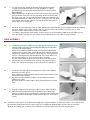
5. a. Glue the pre-shaped 5/16"x1/2"x42" balsa trailing edge to the top of the
trailing edge sheeting and the ends of the wing ribs.
b. Cut a trailing edge fill-in block from the 1/2"x3/4"x5" piece of balsa
included in the kit, and glue it in place. Carve and sand the top of the fill-
in
block to match the W-1 wing ribs.
6.
a. Temporarily remove any pins in the bottom trailing edge sheeting, then
add the 3/32" balsa top trailing edge sheeting (trim the front edge straight
before gluing). For this step it is recommended that you apply Sig-Bond
(aliphatic resin) to the top of the trailing edge, the ribs, and the SW-3
shear webs before setting the top sheeting in place. Re-pin the trailing
edge to the building board to keep it straight while it dries.
b. Trial fit a main spar assembly in the upper rib notches. If any of the shear
webs are too tall, they should be trimmed to allow the spar assembly to sit
all the way down in the rib notches. When satisfied with the fit, glue the
spar assembly in place. Check the root W-
1 rib again with the Dual Tool to
be sure it is still at the correct angle.
c. Glue the pre-shaped 3/8"x3/8"x42" balsa leading edge to the front of the
ribs.
d. Glue the two 1/4" sq. x42" balsa top forward spars in place.
e. Glue the forward-most 1/4" sq. x42" balsa bottom forward spar in place.
(The final forward spar will be added later.)
f. Add the 1/4" sq. x42" balsa top rear spar.
7.
Install a die-cut lite-ply wing dowel support (WDS) in the innermost rib bay
between the two 1/4" sq. spars behind the leading edge. Notice that one end of
the support is pre-cut to match the dihedral angle of the inboard W-1 rib.
8.
Form a 14" long aileron servo lead tube by wrapping one of the supplied pieces
of 8-1/2" x14" plain white paper around a broom handle. Temporarily tape the
tube together, slide it off the broom handle and into the 1" holes in the wing
panel. Position the outboard end of the tube flush with the outer W-2 wing rib.
Remove .the tape and allow the tube to unwind, then glue it to the ribs.
NOTE: Remove any pins from the structure that are located under the area
where the top center sheeting will be installed (in the next step). Otherwise, you
may find it difficult to remove your wing from the board later!
9.
a. Cut the top center sheeting piece that fits between the main spar and the
rear spar from the 3/32"x3" balsa sheet provided in the kit. Trim and sand
the sheet to fit, then glue it in place. Sig-Bond is recommended for gluing
all of the center sheeting to the ribs and spars because it will be easier to
sand the joints smooth later.
b.
The rest of the top center sheeting should be cut from 3/32"x4" balsa, and
glued in place.
10.
When the glue has dried, unpin the wing half from the board and install the
remaining 1/4" sq. x42" balsa bottom forward spar.
IMPORTANT! If you have been using thin or medium CA glue, now is the time to go back over every joint using medium
or thick CA. Don't be stingy here - the integrity of your wing depends upon strong glue joints. Glue BOTH sides of
EVERY joint, even the aileron servo lead tube. Make certain the shear webs are bonded to the spars AND the wing ribs
on each side. Double check the leading edge stick and all of the 1/4" sq. spars for complete bonding to the ribs.

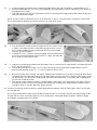
.
11. Install the bottom center sheeting except for the two areas shown in the photo. Cut pieces from the 3/32" x 4" balsa that
you used earlier.
12.
a. Cut off and sand the spars, leading edge, trailing edge, and sheeting at
both ends of the wing, flush with the end ribs.
b. Although the leading edge is pre-shaped, it should be smoothed now with
a long sanding block. Also, trim and sand the overhanging portion of the
trailing edge sheeting flush with the trailing edge.
c. Sand the top center sheeting smooth. (The bottom center sheeting is
sanded later, in step 19.) Cut a 3/4" sq. access hole in the top center
sheeting as shown on the plan.
13.
Glue the die-cut lite-ply wingtip to the outboard end of the wing panel.
OPTIONAL: If you prefer rounded
wingtips over the square ones, simply
add a soft balsa block to the wingtip
(instead of the lite-ply part), then
carve and shape it as desired.
14.
The two center W-1 wing ribs have two
vertical slits between the main spar
notches to help locate the dihedral
brace. Carefully remove the material
between the slits, then extend the
openings to the spars as shown in the
diagram. A small sanding stick made
from scrap 5/32" ply with sandpaper
glued to the edge is a handy tool for this
step.
15.
Repeat steps 2 through 14 to build the
opposite wing half.
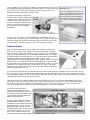
Joining The Wing Panels
16.
a. Trial fit the two wing panelswith the die-cut 5/32" plywood dihedral brace installed between the main wing spars. Be
certain that the dihedral brace is not preventing the panelsfrom making solid contact with each other at the center. If
necessary, trim or sand the dihedral brace for a snug fit. The dihedral angle of 20 per wing panel will be
automatically built-in by the dihedral brace. If you want to check the angle, place the wing on a table so that one
side sits flat, and the other side is raised. The distance from the table to the bottom of the wingtip should be about 2-
3/4", but a variation of up to 1/2" either way is acceptable and will not affect the flight performance. The most
important thing is to have a tight joint at the wing center with no gaps.
b.
Epoxy glue the dihedral brace into ONE of the wing panels, and allow to dry.
17.
Use epoxy (either 5-minute or slow-dry)
to join the two wing panels. Generously
apply glue to end ribs and the exposed
edges of the dihedral brace, then
carefully slide the other wing panel into
place. Wipe away any excess epoxy
that oozes from the center joint (a rag
dampened with alcohol works well).
Before the glue dries, make sure that
the leading and trailing edges of both
panels are perfectly aligned.
18.
Glue the die
-
cut 1/16" plywood wing hold
-
down plates to the bottom of the wing, flush with the trailing edge.

.
Finishing The Wing
NOTE: Complete the steps in "Mounting The Wing To The Fuselage" before proceeding.
19.
a. While you still have access through the bottom of the wing, check the glue
joints around the wing hold-down dowels and the dihedral brace. If
necessary, apply another coating of epoxy to the joints.
b. Finish off the bottom center sheeting, again using 3/32" balsa.
c. If you haven't done so already, give the wing a final sanding. Sand just
enough to take off any prominent high spots or bumps. Excessive sanding
may distort the airfoil shape.
20.
The 2" wide fiberglass tape can be applied to the wing center joint (top and bottom) using one of the following two
methods:
METHOD 1:
1. Coat the wing center joint with slow-drying
epoxy glue.
2. Lay the tape on top of the glue.
3. Holding one end of the tape so it won't slip,
"squeegee" the glue through the tape with
a small paddle of scrap balsa. Scrape over
the tape several times with the paddle to
smooth the tape and remove any excess
glue.
4. When dry, sand lightly to remove any rough
spots. Try not to sand into the fiberglass
tape itself.
METHOD 2:
1. Cut the tape to length, then lightly spray one side with a
spray adhesive (such as 3M "77").
2. Position the tape on the wing center joint.
3. Soak the tape with thin CA. The spray adhesive simply holds
the tape in place - it won't affect the strength of the CA. A
second coat of CA will help fill in the weave of the fiberglass,
resulting in a smoother surface. Rub the second coat with
your finger (protected with plastic wrap - keep it moving!) to
smooth out the glue. Use a fan to keep the CA fumes away
from your face.
4. When dry, sand lightly to remove any rough spots. Try not to
sand into the fiberglass tape itself.
Ailerons
21.
Sand the trailing edge of the aileron round and bevel the front using a sanding block. A pencil line drawn down the center
will help keep the bevel symmetrical.
22.
Imbed the die-cut 1/16" plywood horn
support in the bottom surface of the
aileron by carefully cutting a 1/16" deep
relief as shown in the diagram below
and the "Control Horn Assembly"
diagram on Sheet 2 of the plans. Firmly
glue the support into the relief.
23.
a. Center a nylon control horn on the plywood support with the five horn holes lined-up vertically with the point of the
leading edge bevel. Mark the position of the two flange holes, then drill at the marks with a 3/32" drill bit.
b.
Reinforce the control horn area by soaking the wood around the two holes with thin CA.This will help keep the nylon
horn plate from crushing the balsa when the control horn is installed later.
24.
Temporarily tape the aileron to the back of the wing with its inboard end spaced 2-1/2" from the wing center joint. Sand the
outboard end of the aileron flush with the wingtip. Leave the aileron taped in place and temporarily mount the nylon control
horn to aid in the next section.

.
Aileron Servo Installation
The ailerons on the Four-Star 120 are operated by two servos mounted
separately in each wing panel (see "RADIO REQUIREMENTS" earlier on in these
instructions).
25.
Cut two hatch rails from the special-cut 1/4"x1/2"x12" basswood stick provided in
the kit. Glue the hatch rails in place, flush with the bottom edge of the W-2 and W-
3 wing ribs. The hatch rails provide a seat for the aileron hatch and a flat surface
for attaching the covering material.
26.
a. The die-
cut 1/16" plywood hatch may require some trimming or sanding for
a perfect fit on the hatch rails. With the hatch in place, drill four holes
through both the hatch and the hatch rails (at each corner of the hatch)
with a 1/16" drill bit.
b. Remove the hatch, then redrill the four holes in the hatch with a 3/32" drill
bit. The hatch is held in place with four #2 x 3/8" sheet metal screws. Be
sure to mark each hatch so you can tell later which hatch goes with which
wing panel!
27.
a. Since servos come in many sizes, you need to make a custom servo tray
from lite-ply and basswood to fit your particular servo. Cut a hole in the die-
cut lite-ply aileron servo mount to fit your particular servo. The forelaft
dimension of the hole should be about 1/16" larger than the length of your
aileron servo.
b.
Cut two 3/8" sq. x4" basswood servo rails (from tile 27" long piece provided
in the kit) and glue them to the aileron servo mount flush with the front and
rear edges of the hole.
c.
If necessary, trim or sand the edges of the servo mount until it fits snugly in
position between the ribs. Trial fit the mount, but don't glue it in yet.
28.
Carefully position the servo on the mount so that the outer hole of the servo arm
is lined-up with the control horn on the aileron. The goal here is to keep the
aileron push rod wire parallel to the wing ribs (and the airflow). Mark the 4 servo
mounting holes, then fas.ten the servo to the aileron servo mount using either the
screws provided with the servo or long wood screws (#2 x3/4", not provided in
kit).

.
29.
a. Make an aileron pushrod as shown on the plan from a 4-40 x8" threaded
rod, a 4-40 solder clevis, and a 4-40 R/C link.
The actual length of your pushrod may have to be altered slightly
depending on the shape of your aileron servo.
b. Temporarily connect the aileron pushrod to the servo arm (with the solder
clevis) and the aileron control horn (with the R/C link). Adjust the position
of the servo mount in the wing as necessary to keep the pushrod from
hitting the bottom spar and the servo arm from hitting the hatch.
Also make certain that the covering material on the top of the wing won't
make contact with the servo.
30.
When satisfied with its position, glue the servo mount assembly to the wing ribs.
Reinforce the joints at the servo mount and the ribs with a couple of scrap pieces
of stick balsa.
31.
The plywood hatch will need an opening cut into it for the aileron pushrod.
Again, the exact
-size and shape of this opening will depend on the shape and
position of your pushrod. You can make a nice-looking slot by drilling two holes,
then connecting the edges with knife cuts.
When you are done with the hatch, remove the aileron, the aileron control horn,
and the aileron pushrod; The servo can be left in place since it won't interfere
with covering.
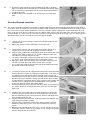
ALTERNATE AILERON SERVO INSTALLATION
You may prefer to install your aileron servo as
shown in the diagram below. The advantages are
that the push rod can be run directly to the control
horn with no bends, it's lighter, less complex, and
provides easier servo access. The disadvantages
are a slight increase in drag and a less "finished"
look to the bottom of the wing. Simply replace the
hatch rails and plywood hatch with some 3/32"
balsa sheet (trim the bottom of the ribs to fit), and
cut an opening that's just large enough to install
and remove the servo.

.
FUSELAGE CONSTRUCTION
Fuselage Subassemblies
Before starting fuselage construction, there are a few subassemblies that should be built and set aside until needed. This
is done to avoid interruptions during the flow of fuselage construction.
32.
a. Glue together the two die-cut 5/32" plywood F-1 pieces using Kwik-Set epoxy or
slow CA. Use a heavy weight of some kind to hold the two pieces perfectly flat
while drying.
b. Mark the vertical center line and thrust line on the F-1 assembly using the cross-
section on the plan as a guide.
c. The engine mount included in the kit will fit most of the 1.20-size four-stroke
engines on the market. Positon the engine mount (or another mount of your
choice) on F-1, mark the location of the mounting holes, then drill them out with a
3/16" drill bit.
33.
a. Lightly hammer four 6-32 blind nuts into the back of F-1. Pull the blind nuts into their final position by bolting the
engine mount to the front of F-1 using four 6-32 x3/4" socket head bolts. Apply medium or slow CA around the
edges of the blind nuts to hold them in place. Be careful not to get any glue in the threads!
b. Position your engine on the mount far enough forward for the propeller to clear the fuselage "cheeks", mark the
engine mounting holes, then drill at each of the marks. If you plan on using the four #8 x1" sheet metal screws
provided in the kit, use a 9/64" dia. drill bit. The sheet metal screws are self-tapping and won't loosen from engine
vibration. If you prefer, machine screws can be substituted, but you'll have to drill and tap the mount.
34.
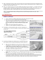
Temporarily bolt the engine to the
mount so you can locate the best spot
on F-1 for the throttle pushrod to exit
and line up with your engine's
carburetor control arm. A 2-56 solder
clevis is provided in the kit to attach the
flexible cable pushrod to the engine's
carburetor. The solder clevis should
work well for 2
-
stroke engines, but most
4-
stroke engines may require a different
type of connector. Remove the engine
and engine mount, and drill at the mark
with a 9/64" dia. drill bit.
35.
a. Glue the two die-cut 5/32"
plywood landing gear mounts
together with epoxy or slow CA.
Again, weight the assembly
down until dry.
b. Carefully center the aluminum
landing gear over the landing
gear mount and mark the
location of the mounting holes
through the three holes in the
landing gear. Remove the mount
and drill at the marks with a
13/64" drill bit.
c. Lightly hammer three 8-32 blind
nuts into the holes and secure
them with medium or slow CA.

.
36. a. Notice that the die-cut lite-ply former F-2 has two dimple marks which are used to locate the holes for the wing hold-
down dowels. Glue F-2D to the die-cut lite- ply former F-2 so that the dimples remain showing.
b. Drill at the dimples in F-2, first with a 1/8" drill bit, then with a 1/4" drill bit, and finally with a 5/16" drill bit. Use a
chunk of hardwood behind the formers to keep the plywood from splintering as you drill through.
37.
Glue the die
-
cut lite
-
ply tailwheel mount (TWM) to aft end of FBR (Fuselage Bottom, Rear).
Basic Fuselage Construction
38.
a. The fuselage sides are spliced from two die-cut pieces. Align the pieces directly over the plan (protected with wax
paper), then apply medium CA to the splice joint.
b. Glue the die-cut fuselage doublers to the fuselage sides using slow CA or Kwik-
Set epoxy, and allow to dry. Be sure
to make one left side and one right side!
39.
a. Carefully slip all the fuselage formers (F-1 through F-G) into place between the fuselage sides. Put a rubber band
around the fuselage at each former location to hold it tightly together.
b. Slide the die-cut lite-ply part FBR (Fuselage Bottom, Rear) under the rubber bands until it snaps into its proper
location between the fuselage sides. Do the same thing for the die-cut lite-ply part FT (Fuselage Top) and the die-
cut lite-ply Stab Support.
NOTE: The "Tee-Lock" tabs on the formers, FBR, and FT are made oversized to protrude past the fuselage sides. These
will be sanded off after the fuselage has been completely assembled.
40.
a. Place the fuselage over the top view on the plans to check its alignment. Even if some of the plywood is badly
warped, the interlocking parts are designed to be self-
aligning. If there are any persistent warps or twists, now is the
time to fix it! Once the fuselage is glued, it can't be re-
aligned. Double check that the opening at the back end of the
fuselage is square with the fuselage top. If necessary, gently twist or push the parts in the desired direction and use
masking tape to hold them there.
b. Carefully glue all of the parts permanently in place, preferably working from inside of the fuselage, using medium
CA. Start with small patches of glue in the corners, checking the fuselage alignment as you go. Then go back and
glue all of the joints on both sides. Leave the rubber bands and tape in place until all of the glue has dried
completely.
BUILDER'S TIP:
To assist in keeping the nose
section of the fuselage straight,
you can install the die-cut lite-ply
tank floor at this point, but it is
very important not to glue it in
place during part "b" of this step.
The tank floor should not be
glued in until step 45. Notice
that if you use the provided
engine mount, you will need to
cut some clearance notches at
the front of the tank floor to clear the two bottom blind nuts and mounting
bolts.
41.
a. Glue F-4T and F-5T to their slots in FT.
b. Add the die-cut lite-ply headrest HR to the top of FT. Use the 25 deg. side of the Dual Tool to get the correct angle.
42.
a. Glue the five 3/16"x3/8"x24" balsa fuselage stringers in place. Notice that the top stringer and the two bottom
stringers sit in notches in F-G, while the two middle stringers butt against the front face of F-G.
b. When dry, trim off the front of the stringers flush with the front of HR and the back of F-G. Save the scrap stringer
material for later.

.
43. a. Install the landing gear mount to the fuselage by gluing it firmly to the sides, the doublers, and the bottom of F-2.
b. Bevel the bottom edge of F-1 as necessary to allow FBF (Fuselage Bottom, Front) to seat properly in its grooves on
the bottom of the fuselage.
c. Tape FBF in place, then glue it using medium CA. Be sure to firmly glue the joint between FBF and the landing gear
mount from inside the fuselage.
NOTE: The hole in FBF is provided to serve as an oil drain hole, as well as a convenient place to route the vent line from
the fuel tank and/or the breather line from the crankcase of a four
-
stroke engine.
44.
a. If the tank floor was installed earlier for alignment reasons, remove it now.
Cut two 1-3/8" lengths from the 3/4"x30" balsa triangle stock to serve as
braces for the landing gear mount. Notch both braces to clear the blind
nuts, then glue them in place.
b. Cut two braces for F-
1 from the 3/4" balsa triangle stock and notch them as
necessary to clear the blind nuts on the back of F-1. Apply slow CA to the
braces and press them firmly in place.
45.
a.
Now you can permanently install the tank floor. Make sure it is seated on the fuselage doublers and against the back
of F-1, then glue it in place.
b. Trim the die-cut lite-ply nose triplers as necessary to fit, then glue them firmly to the fuselage doublers and F-1.
c. Glue the small top deck formers T-1 , T-2, and T-3 into their notches in FT.
46.
a. Bevel the top edge of the fuselage sides with a sanding block to provide a firm seat for the fuselage top deck when it
is installed. Notice that the angle between the top deck and the fuselage sides varies along the entire length. Use the
top deck formers as a guide to the sanding angle. Don't worry about perfection - a few swipes with a sanding block
on each side should do the trick.
b. Tape the die-cut balsa top deck in place. You will probably need to apply some warm water to the upper surface of
the top deck to make it easier to bend into position and prevent it from cracking. Apply medium CA from inside the
fuselage as much as possible. When dry, remove the tape.
47.
Check the fuselage for joints that could use another application of medium or slow CA. Fill any gaps at the Tee-Lock tabs
and slots with CA.
The fuselage should now be ready for final sanding. Sand off all of the Tee-Lock tabs, then round the bottom edges of the
fuselage and the corners of the balsa top deck. Use a sanding block, starting with 80-grit sandpaper. Switch to 150-grit,
then 220-grit or 360-grit for the final sanding.

.
Mounting The Wing To The Fuselage
NOTE: The wing must be completed through step 18 before proceeding.
48.
a. Trial fit the wing to the fuselage. Align the wing (see the General Alignment
Diagram on page 20 of "The Basics of Radio Control") and make accurate
pencil marks on both the wing and fuselage so that the wing can be
returned to the same position later.
b. Locate the two 5/16" dia. x2" wing dowels and sharpen one end of each to
a point - keep the point symmetrical and centered. Push the dowels into
the holes in F-2 so that only the points remain sticking out into the wing
opening. Slide the wing into position, making sure it is centered on the fuselage. When you remove the wing, there
should be two small indentations in the leading edge.
49.
a. Drill 1/8" holes through the leading edge at the indentations. Re-drill the holes, this time with a 5/16" drill bit, and
continue drilling straight through the lite-ply wing dowel supports that are already installed in the wing. Keep the drill
aligned as best you can with the wing center line.
b. Remove the wing dowels from F-2. Put a piece of wax paper over the face of F-2 and reinsert the dowels, forcing
them through the wax paper. Push the dowels in only 3/8", leaving most of their length exposed.
c. Trial fit the wing in position, sliding it onto the dowels. Check to see that the wing seats properly on the fuselage. If
not, slowly enlarge the holes in the leading edge until it does seat properly.
50.
When satisfied with the fit of the wing and the wing dowels, coat the inside of the holes in the leading edge with epoxy. Slide
the wing back into position on the dowels. Also apply epoxy to the aft end of the wing dowels and the wing dowel supports
by working through the openings in the bottom center sheeting. Hold the wing in place until dry, then remove the wing and
fill any gaps around the dowels with another application of glue.
51.
a. The two 3/4"x3/4"x1-1/2" basswood wing hold-down blocks key into pre-
cut notches in the -fuselage doubler. For an accurate fit, the side of each
block that contacts the fuselage needs to be beveled slightly to match the
aihedral angle of the wing. Temporarily tape the wing in place on the
fuselage, then check the fit of the blocks by working through the lightening
holes. The blocks should seat firmly against both the fuselage side and the
top surface of the wing.
b. Again working through the lightening holes, install the wing holddown
blocks in the notches, making certain they are in full contact with the wing
upper surface. Tack glue the blocks to the fuselage with slow CA, then
remove the wing. Finish gluing the blocks in place using medium CA.
c. Cut two 1-1/2" lengths of 3/4" balsa triangle stock to brace the wing hold-
down blocks. Glue the triangle braces firmly
to the top of the holddown blocks and the fuselage doublers.
52.
a. Fit the wing in place on the fuselage and check its alignment one last time.
When you are satisfied that it is aligned correctly, tape it so that it can't
move.
b. Carefully mark the drill locations for the wing bolts. Visually confirm that a
hole drilled at the marks will pass through the approximate center of the
basswood hold-down blocks.
c. Drill through both the wing and the wing hold-down blocks with a #7 (or
13/64") drill bit. Keep the drill perpendicular to the bottom surface of the
wing so the heads of the nylon wing bolts will seat flush against the
plywood plates.

.
53. a. Remove the wing and tap the wing hold-down blocks with a 1/4-20 tap.
Apply a few drops of thin CA to the holes to strengthen the threads. When
you are absolutely certain that the CA has cured, clean up the threads by
re-tapping the holes.
b. Redrill the holes in the wing with a 1/4" drill bit to pass the nylon wing
bolts.
Servo And Pushrod Installation
54.
The servos need to be mounted in the fuselage so that the nylon push rods can be routed properly, with the least amount
of curvature. Refer to Chapter 2 of "The Basics of Radio Control" and the plans for information on where and how to mount
the servos in the fuselage. Start by cutting two 4-1/4" long servo rails from the supplied 3/8" sq. basswood stick. The ends
of the servo rails searin the die-cut lite-ply servo rail supports (SRS), which in turn slide against the "flat" inner edge of the
fuselage doubler. Use your servos (or servo tray if you plan on using one) to properly space the servo rails. When satisfied
with their position, glue the servo rails and servo rail supports in place.
55.
a. Lock the rails in place by gluing a scrap piece of lite-ply or balsa at each
end of both rails.
b. Mount your rudder, elevator, and throttle servos to the rails.
56.
a. Locate the two .270 o.d. x36" nylon outer pushrod tubes (black), and
roughen the last 4" of each with sandpaper to aid glue adhesion.
b.
Slide the outer pushrod tubes forward through the pushrod exit slots in the
fuselage sides and the notches in F-6. Continue sliding the tubes until
only about an inch sticks out past the slots.
c.
The outer pushrod tubes should nearly meet (but not cross) at the notch in
F-5. Glue a scrap of balsa below the tubes to hold them in place.
d. Apply glue (either slow CA or epoxy) to the outer tubes at the push rod
exit slots, from both the inside and the outside of the fuselage.
e. Use a single-edge razor blade to trim the outer pushrod tubing flush with
the outside surface of the fuselage.
57.
a.
The nylon push rods must be supported at each former to keep them from
flexing under load. Use the die-cut lite-ply pushrod straps, F-3S and F-
4S,
to support the push rods. Notice that the pushrod straps haven't been
marked for push rod location because the routing of the pushrods will vary
with different servo installations. Ideally, you want to have the push rods
to come through F-3S pointed directly at fhe servo arms of the rudder and
elevator servos. Carefully mark the pushrod locations on the plywood
straps, then drill at the marks with a 9/32" drill bit.
b. Cut off the front ends of the outer push rod tubes about an inch forward of
F-3. Slide F-4S then F-3S into position on the push rods, but don't glue
them in yet.
58. a. Cut two 4-40 x 8" threaded rods to an overall length that is equal to the
distance from your servo arm to the end of the black tube (this distance
will vary depending on your servo placement). Solder a 4-40 solder clevis
to the smooth end of each rod.
b. Screw the threaded end of the rods completely into the two .200 o.d. x36"
nylon inner pushrod tubes (yellow).
c. Slide the inner pushrod tubes into the outer tubes from the servo end.
Attach the solder clevises to the servo arms and hook them up to the
servos.
d. With the push rods hooked up to the servos, you can now glue F-3S and
F-4S to the front of F-3 and F-
4, respectively, in such a way as to keep the
bends in the push rods to a minimum.

.
59. Now is a good time to install the .130 o.d. nylon outer tubing (clear) for the throttle pushrod. Route the tubing with as little
curvature as possible, and support the aft end with a scrap balsa standoff. A SIG pushrod connector is supplied in the kit to
hookup the cable to the throttle servo arm.
60.
Now is also a good time to plan your fuel tank installation and routing of fuel lines through F-1 (see "Engine and Fuel Tank
Installation" for more information on fuel tanks for the FOUR-STAR 120). Mark the locations of the fuel lines on F-1, then
drill holes through F-1 at the marks with a drill bit that is the same diameter as your fuel tubing. If you haven't done so
already, remove the engine, fuel tank, throttle cable, and inner nylon pushrods before proceeding.
NOTE: The final step in the fuselage assembly is to attach the tail fairing blocks and shape them on the fuselage. Since this
requires a completed stabilizer and fin, the instructions for this step are included under the next section, "TAIL
CONSTRUCTION".
TAIL CONSTRUCTION
Stabilizer and Elevator
61.
a. Cut the 1/4"x3/4" balsa stabilizer trailing edge to length and pin it in place over the plan.
b. Glue the 1/4" sq. x9" spruce stab brace to the balsa trailing edge.
c. The 1/4"x2"x12" balsa sheet provided in the kit must be used for both the
stabilizer center block and the fin base. There is very little excess, so cut
these parts carefully. First, cut out the stabilizer center block, using the
plans as a guide, then glue it firmly to the stab brace and pin it to the
plans.
d. Add the 1/4"x3/4" balsa leading edges and tip pieces.
e. Add the 1/4" sq. balsa diagonals to complete the stabilizer frame.
62.
The stabilizer is sheeted on both sides with 1/16" balsa. Cut two pieces of
1/16"x4"x30" balsa as shown in the diagram, and glue the parts together to make
two stab skins.
BUILDER'S TIP: Use Sig-Bond for
gluing the sheets, and sand the joints
smooth BEFORE attaching them to the
stabilizer frame. Sanding the skins
after attaching them to the framework
can result in a "ripple effect" due to the
underlying structure.
63.
Sand the top and bottom of the stabilizer frame to smooth out the glue joints.
Also sand the ends of the leading and trailing edges to match the tip pieces.
64.
a. Apply slow CA or Sig-Bond to cine entire side of the stabilizer frame, then
immediately press it onto one of the stabilizer skins. Trim the first skin with
a modeling knife, then repeat for the opposite skin and allow to dry.
b. Sand the sheeting flush with the stabilizer frame, then round the leading
edges with a sanding block. Sand a small flat spot at the center "point" of
the stabilizer so that it will seat against former F-6.
65. a. Locate the two pre-cut 3/8" balsa elevators and sand their trailing edges round. Draw a hinge line centered on the
leading edge of each elevator, then use a sanding block to bevel the front of the elevators using the hinge line as a
guide.
b. Imbed the die-cut 1/16" plywood elevator horn support (EHS) in the bottom of the left elevator. Drill two mounting
holes for the elevator control horn, and reinforce the balsa around the holes with thin CA.
c. Use the plans to mark the elevators where the 1/8" dia. music wire elevator joiner will attach. Drill and groove the
leading edges to accept the elevator joiner. Sand the joiner wire and wipe it clean before gluing it to the elevators
with Kwik
-
Set Epoxy. Be certain to keep the leading edges of both elevators aligned as the glue dries.

.
66. Temporarily tape the elevators to the back of the stabilizer, then use a sanding block to sand both of them at the tips until
they match perfectly. The tips can be left square or sanded round if you prefer.
Fin and Rudder
67.
a.
Cut the 1/4"x3/4" balsa fin trailing edge to length and pin it in place over the
plan. Notice that the fin trailing edge extends to the bottom of the fuselage.
b. Cut the fin base from the remaining piece of 1/4"x2" balsa sheet. and then
pin it in place over the plan.
c. Add the 1/4"x3/4" balsa leading edge and top piece.
d. Add the 1/4" sq. balsa diagonals to complete the fin frame.
68.
Cut a piece of 1/16"x4"x30" balsa as shown in the diagram, and glue the parts
together to make two fin skins. Use Sig-Bond for gluing the sheets, and sand the
joints smooth BEFORE attaching them to the fin frame.
69.
a. Sand both sides of the fin frame smooth with a large sanding block. Trim
the ends of the fin leading and trailing edges to their final shape.
b. Draw a line on both sides of the fin trailing edge 3/8" below the fin base.
c. Apply slow CA or Sig-
Bond to one entire side of the fin frame except for the
area below the line that you have just drawn.
d. Repeat the above step for the other side of the fin.
70.
When dry, trim the sheeting flush with the fin frame. Use a sanding block to sand
the fin leading edge round. Finish the fin by sanding a small flat spot at the bottom
of the leading edge to fit against former F-6. Temporarily pin or tape the stabilizer
to the fuselage, then trial fit the fin in place. You may have to trim the length of the
fin trailing edge to allow the fin base to seat firmly on top of the stabilizer. Leave
the fin in place until after the tailwheel has been fitted.
71.
a. Round off the trailing edge and bottom of the pre-
cut 3/8" balsa rudder, and
bevel the leading edge.
b. Imbed the die-cut 1/16" plywood rudder horn support (RHS) in the right
side of the rudder. Drill the two mounting holes for the rudder control horn,
and reinforce the balsa around the holes with thin CA.
c. Cut a slot in the bottom edge of the rudder to accept the tailwheel wire.

.
72. a.
Tape the rudder to the fin so that
its bottom edge is aligned with
the fuselage bottom.
b. Sand the top of the fin or rudder
as necessary so that they will
line-up when installed later.
c. With the rudder still taped in
place on the fuselage, trial fit the
tailwheel assembly. Adjust the
bends in the wire as necessary
until the nylon bracket seats
properly on the fuselage bottom
and the tailwheel itself is aligned
with the rudder.
d. When satisfied with the fit, sand
and wipe clean the top of the
tailwheel wire, then glue it into
the slot in the bottom of the
rudder with epoxy. Tape the
nylon tailwheel bracket to hold it
in position on the fuselage until
the glue dries.
e. Allow the epoxy to dry, then
reinforce the tailwheel area with
a 2-1/2" long piece of 2" wide
fiberglass tape applied with
another batch of epoxy. When
dry, remove the rudder along
with the entire tailwheel
assembly from the fin.
NOTE: The tailwheel bracket will
be attached to the fuselage
during final assembly.
BUILDER'S TIP:
Two #2 flat washers are included in the kit to act as retainers for the tailwheel.
Of course, you can use 3/32" wheel collars (not included in kit), but the soldered
washers give a more "finished" look.
1. The secret to successful soldering is cleanliness. Sand
the wire and the washers, then wipe them clean with
alcohol. Begin the job by soldering the inner washer, which
can be held in place with a temporary piece of heat-proof
silicone fuel tubing.
2. When cool, install the tailwheel followed by a thin
cardboard spacer and the outer washer.
3. Solder the washer, allow to cool, then remove the
cardboard spacer. Grind off the excess wire and file the end
smooth.
Done properly, this installation should be completely trouble-free.
73.
The balsa tail fairing blocks can now be glued to the fuselage using the stabilizer
and fin to position them accurately. Cut two 4" lengths of 3/4" balsa triangle stock
to serve as tail fairing blocks. Make sure your fin is centered on the fuselage (as
viewed from above), then carefully glue the fairing blocks to the back of F-6 (not
the tail surfaces!) Gently slide the fin and stabilizer off the fuselage and apply a
second coat of glue to the front of the fairing blocks.
74.
Temporary spacers are used to support the fairing blocks during shaping. Spot
glue the 3/8"x3/4"x2" balsa spacer to the stab support centered under the fairing
blocks. Glue a scrap piece of 3/16"x3/8" balsa to the top of the spacer between
the fairing blocks. Finally, spot glue the fairing blocks to the spacers.
75.
Carve and sand the fairing blocks to
blend in smoothly with F-6 and the
fuselage stringers. Usea sanding block
with one end wrapped with paper to
protect the stringers from the
sandpaper. When done, carefully cut
away the glue spots holding the spacers
to the fuselage and the fairing blocks.
You can remove the spacers now; just
be careful of the fragile fairing blocks
during covering.
76. OPTIONAL:
If you plan on installing the optional
tail brace wires (see "Final Assembly"
for more information), you need to
reinforce the attach points on the fin
and stabilizer. Use the six die-cut
1/16" plywood brace wire pads
(BWP) for hard points. Use a sharp
knife to carefully cut away the balsa
sheeting in the positions shown on
the plans (four places on the
stabilizer, two on the fin). Glue in the
plywood pads, then drill three attach holes with a 3/32" drill bit, right at the
center of the plywood pads. Harden the balsa between the pads by applying a
few drops of thin CA directly into the holes.

.
COVERING
General Instructions
We recommend that you cover the wing, fuselage, tail surfaces, and control
surfaces all separately before hinging and final assembly. This way, the parts
are much easier to handle. Before choosing the covering for your model, please
refer to the list of approved covering materials that has been included with this
kit. The open structure design of the Four-Star 120 wing relies partially on the
covering to aid in torsional stiffness, so it is very important that you use an
approved covering material.
Our Four-Star 120 prototypes were covered with either Sig Supercoat iron-on
plastic film or Sig Koverall fabric. Sig Supercoat is ideal for sport models
because it's lightweight and easy to apply. Sig Koverall is extremely durable and
adds tremendous strength to the structure with only a slight weight penalty over plastic films. Use Supercoat film if you're
looking for maximum performance with a 1.20 four-stroke or .90 two-
stroke engine. If you plan on using a gas engine or an
engine in the upper end of the recommended engine range, Koverall would be your best choice.
The following instructions provide advice and procedures specific to covering the Four-Star 120 with either Sig Supercoat
or Sig Koverall. If you choose another brand of covering material, be sure to read the manufacturer's directions (supplied
with the covering) and follow them carefully.
Surface Preparation
A good covering job starts with good surface preparation. Regardless of what type of covering you choose, it won't hide
poor workmanship. Fill any small surface gaps or dents with a lightweight filler or spackling paste. Sand the entire model,
including the ailerons and tail surfaces, with 220-grit sandpaper, then again with 360 or 400-grit sandpaper.
Two areas of the fuselage require further preparation before covering the engine compartment and the cockpit. Since it's
too difficult to apply covering material to the engine compartment, it must be fuel-
proofed using several coats of clear dope
or two coats of polyester (glass) resin, sanded between coats. Finish off the engine area with a few coats of colored Sig
Supercoat Dope. (Most of the Supercoat plastic iron-on films have a matching Sig Supercoat Dope color.)
The cockpit floor can be painted or covered with plastic film. The front of the headrest (HR) shouldn't be covered or
painted until after the fuselage stringer area has been covered, to help hide the seam. Cut the instrument panel from the
decal sheet and apply it to former T
-
3 to finish off the cockpit.
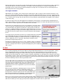
Covering with Sig Supercoat Iron
-
On Plastic Film
You will need four rolls of Supercoat (color of your choice) to cover the FourStar 120. You will need one big piece from
each roll (about 14
-
1/2"x42") to cover the wing. Use the rest of the film to cover all of the remaining parts.
Covering The Wing
Begin the wing by covering the wingtips and plywood hold-
down plates. On the wingtips, run the covering material "around
the corner" about 1/8". Later, when the main top and bottom covering pieces are applied, they will overlap the wingtip
covering and can be trimmed at the wingtip corners, leaving a virtually invisible seam. Extend the covering material about
1/8" past the outside edges of the hold-down plates, again to provide an area for overlap.
Cover the main portion of the wing starting with the bottom and then the top so that the seams will be on the bottom where
they will be less visible. The top covering should overlap the full width of the leading & trailing edges. Wait until both the
top and bottom pieces of covering material have been sealed completely around their edges before shrinking the large
open areas between the ribs. Alternate between the top and bottom surface to avoid uneven shrinking which could cause
a warp. Your sealing iron or a special "heat gun" can be used (household blow dryers don't provide enough heat). Keep
the heat gun moving at all times or you may burn a hole in the covering. If you notice the covering material "ballooning up",
put a small pin hole in the bottom of each rib bay to allow the expanding air to escape. To maximize the torsional stiffness
of the wing, be sure to firmly bond the covering material to all of the spars and ribs by going over them again with your
sealing iron.
Cut an "X" pattern at the hatch openings on the bottom of the wing, then iron the excess material to the spars and hatch
rails. Don't forget to cover the outer surface of the plywood hatches, wrapping the covering around the edges about 1/8".
Page is loading ...
Page is loading ...
Page is loading ...
Page is loading ...
Page is loading ...
Page is loading ...
Page is loading ...
Page is loading ...
Page is loading ...
Page is loading ...
-
 1
1
-
 2
2
-
 3
3
-
 4
4
-
 5
5
-
 6
6
-
 7
7
-
 8
8
-
 9
9
-
 10
10
-
 11
11
-
 12
12
-
 13
13
-
 14
14
-
 15
15
-
 16
16
-
 17
17
-
 18
18
-
 19
19
-
 20
20
-
 21
21
-
 22
22
-
 23
23
-
 24
24
-
 25
25
-
 26
26
-
 27
27
-
 28
28
-
 29
29
-
 30
30


Ask a question and I''ll find the answer in the document
Finding information in a document is now easier with AI
Related papers
Other documents
-
Luxor MMGB4836 Operating instructions
-
 Furniture of America IDF-AC291BK-3 Installation guide
-
 BLOTZ B06-MW-105 Assembly Instructions
-
 HERR HRR114 User manual
-
Summit Commercial BIM44GIFADA Installation guide
-
Summit FF7BKBIIFADALHD Operating instructions
-
-
-
-
AccuCold AL55IFE Installation guide


