Acome Izilink GIGA
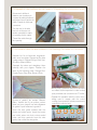
Acome Izilink GIGA is a networking device that enables users to connect their devices using an Ethernet protocol. The pack includes:
- A 40-meter reel of 2.3 x 3.7 mm Gigabit Ethernet micro cable.
- Two 2-meter Gigabit Ethernet cords.
- Two connection units with double-sided adhesive tape.
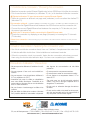
The product is designed to be easy to use, with a simple installation process:
- Place the connection units near the equipment to be connected and run the cable between them.
- Cut the cable to the required length and strip the sheath over about 4 cm.
- Open the connection unit and cut out the pre-cut section to make an opening for the cable; then thread the cable through the opening.
Acome Izilink GIGA
Acome Izilink GIGA is a networking device that enables users to connect their devices using an Ethernet protocol. The pack includes:
- A 40-meter reel of 2.3 x 3.7 mm Gigabit Ethernet micro cable.
- Two 2-meter Gigabit Ethernet cords.
- Two connection units with double-sided adhesive tape.
The product is designed to be easy to use, with a simple installation process:
- Place the connection units near the equipment to be connected and run the cable between them.
- Cut the cable to the required length and strip the sheath over about 4 cm.
- Open the connection unit and cut out the pre-cut section to make an opening for the cable; then thread the cable through the opening.


-
 1
1
-
 2
2
-
 3
3
-
 4
4


Acome Izilink GIGA
Acome Izilink GIGA is a networking device that enables users to connect their devices using an Ethernet protocol. The pack includes:
- A 40-meter reel of 2.3 x 3.7 mm Gigabit Ethernet micro cable.
- Two 2-meter Gigabit Ethernet cords.
- Two connection units with double-sided adhesive tape.
The product is designed to be easy to use, with a simple installation process:
- Place the connection units near the equipment to be connected and run the cable between them.
- Cut the cable to the required length and strip the sheath over about 4 cm.
- Open the connection unit and cut out the pre-cut section to make an opening for the cable; then thread the cable through the opening.
Ask a question and I''ll find the answer in the document
Finding information in a document is now easier with AI
in other languages
- français: Acome Izilink GIGA Guide d'installation
Other documents
-
Whirlpool 1200 User manual
-
-
ELICA ECL148S4 Installation guide
-
Halo H471RICAT Operating instructions
-
-
Gecko in.xtend Techbook
-
Eneo EDC-AKS1 Installation And Operating Instructions Manual
-
NuTone NM100WH User manual
-
Whirlpool UVL6036JSS User guide
-
KitchenAid KXD4636YSS User manual