
BE
DIENUNG UND INSTALLATION
OPERATION AND INSTALLATION
UTILISATION ET INSTALLATION
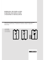
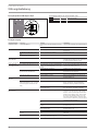
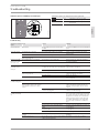
Elektronisch ge
regelter Kompakt Durchlauferhitzer | Electronically controlled
instantaneous water heater | Chauffe-eau instantané compact à régulation
électronique
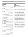
» DCE 11/13
» DCE 11/13 H
» DCE 11/13 RC
1
+
-
2
°C
40
50
60
30
20
°C
40
50
60
30
20

2 |DCE 11/13| DCE 11/13 RC| DCE 11/13 H www.stiebel-eltron.com
INHALT | BESONDERE HINWEISE
BESONDERE HINWEISE
BEDIENUNG
1. Allgemeine Hinweise ����������������������������������������3
1.1 Sicherheitshinweise ��������������������������������������������� 3
1.2 Andere Markierungen in dieser Dokumentation ���������� 3
1.3 Maßeinheiten ����������������������������������������������������� 3
2. Sicherheit �����������������������������������������������������3
2.1 Bestimmungsgemäße Verwendung ������������������������� 3
2.2 Allgemeine Sicherheitshinweise ������������������������������ 3
2.3 Prüfzeichen ������������������������������������������������������� 4
3. Gerätebeschreibung �����������������������������������������4
4. Einstellungen �������������������������������������������������4
4.1 DCE11/13 | DCE11/13H �������������������������������������� 4
4.2 DCE11/13RC ����������������������������������������������������� 4
4.3 Verbrühschutz/ Temperaturbegrenzung ������������������� 5
4.4 Nach Unterbrechung der Wasserversorgung �������������� 5
5. Reinigung, Pflege und Wartung ����������������������������5
6. Problembehebung �������������������������������������������6
INSTALLATION
7. Sicherheit �����������������������������������������������������7
7.1 Allgemeine Sicherheitshinweise ������������������������������ 7
7.2 Vorschriften, Normen und Bestimmungen ����������������� 7
8. Gerätebeschreibung �����������������������������������������7
8.1 Lieferumfang ����������������������������������������������������� 7
8.2 Zubehör ������������������������������������������������������������ 7
9. Vorbereitungen ����������������������������������������������� 7
9.1 Montageort ������������������������������������������������������� 8
9.2 Mindestabstände ������������������������������������������������ 8
10. Montage �������������������������������������������������������9
10.1 Standardmontage������������������������������������������������ 9
11. Inbetriebnahme �������������������������������������������� 10
11.1 Erstinbetriebnahme �������������������������������������������� 10
11.2 Übergabe des Gerätes ����������������������������������������� 10
11.3 Wiederinbetriebnahme ���������������������������������������� 10
12. Außerbetriebnahme ��������������������������������������� 10
13. Montage-Alternativen ������������������������������������� 10
13.1 Wählbare Anschlussleistung ��������������������������������� 10
13.2 Verbrühschutz/ Temperaturbegrenzung ������������������ 11
13.3 Umbau Elektroanschluss unten ������������������������������ 11
14. Störungsbehebung ����������������������������������������� 11
15. Wartung ����������������������������������������������������� 13
16. Technische Daten ������������������������������������������� 14
16.1 Maße und Anschlüsse ����������������������������������������� 14
16.2 Elektroschaltplan ����������������������������������������������� 14
16.3 Einsatzbereiche / Umrechnungstabelle �������������������� 14
16.4 Druckverluste ���������������������������������������������������� 15
16.5 Störfallbedingungen ������������������������������������������� 15
16.6 Landesspezifische Zulassungen und Zeugnisse ���������� 15
16.7 Angaben zum Energieverbrauch ���������������������������� 15
16.8 Datentabelle ����������������������������������������������������� 15
BESONDERE HINWEISE
- Das Gerät kann von Kindern ab 3 Jahren sowie
von Personen mit verringerten physischen, sen-
sorischen oder mentalen Fähigkeiten oder Man-
gel an Erfahrung und Wissen benutzt werden,
wenn sie beaufsichtigt werden oder bezüglich
des sicheren Gebrauchs des Gerätes unterwiesen
wurden und die daraus resultierenden Gefahren
verstanden haben. Kinder dürfen nicht mit dem
Gerät spielen. Reinigung und Benutzer-Wartung
dürfen nicht von Kindern ohne Beaufsichtigung
durchgeführt werden.
- Die Armatur kann während des Betriebs eine
Temperatur von über 60 °C annehmen. Bei
Auslauftemperaturen größer 43 °C besteht
Verbrühungsgefahr.
- Das Gerät muss über eine Trennstrecke von min-
destens 3 mm allpolig vom Netzanschluss ge-
trennt werden können.
- Das Netzanschlusskabel darf bei Beschädigung
oder Austausch nur durch einen vom Hersteller
berechtigten Fachhandwerker mit dem originalen
Ersatzteil ersetzt werden.
- Befestigen Sie das Gerät wie in Kapitel „Installati-
on/ Montage“ beschrieben.
- Beachten Sie den maximalen zulässigen Druck
(siehe Kapitel „Installation/ Technische Daten/
Datentabelle“).
- Entleeren Sie das Gerät wie in Kapitel „Installati-
on / Wartung / Gerät entleeren“ beschrieben.
KUNDENDIENST UND GARANTIE
UMWELT UND RECYCLING
MONTAGESCHABLONE IM MITTELTEIL DIESER ANLEITTUNG
Page is loading ...
Page is loading ...
Page is loading ...
Page is loading ...
Page is loading ...
Page is loading ...
Page is loading ...
Page is loading ...
Page is loading ...
Page is loading ...
Page is loading ...
Page is loading ...

DEUTSCH
www.stiebel-eltron.com DCE 11/13| DCE 11/13 RC| DCE 11/13 H | 15
INSTALLATION
Technische Daten
Nutztemperatur ca. 38°C für Handwäsche etc.
Mischwassermenge
Gerät kW 11 13,5
Kaltwasser Zulauftemperatur
6°C l/min 5,0 6,1
10°C l/min 5,7 6,9
14°C l/min 6,6 8,1
Tabellenwerte sind auf eine Nennspannung von 400 V bezogen.
Die Mischwassermenge und Auslaufmenge ist abhängig vom vor-
handenen Versorgungsdruck und der anliegenden Spannung.
16.4 Druckverluste
Armaturen
Druckverlust bei Durchflussmenge 10l/min
Einhandmischer, ca. MPa 0,04 - 0,08
Thermostatarmatur, ca. MPa 0,03 - 0,05
Handbrause, ca. MPa 0,03 - 0,15
Rohrnetz-Dimensionierungen
Zur Berechnung der Rohrnetz-Dimensionierungen ist für das Gerät
ein Druckverlust von 0,1MPa zu berücksichtigen.
16.5 Störfallbedingungen
Im Störfall können in der Installation kurzfristig Belastungen von
maximal 80 °C bei einem Druck von 1,0 MPa auftreten.
16.6 Landesspezifische Zulassungen und Zeugnisse
Prüfzeichen sind auf dem Typenschild ersichtlich.
16.7 Angaben zum Energieverbrauch
Die Produktdaten entsprechen den EU-Verordnungen zur Richtli-
nie für umweltgerechte Gestaltung energieverbrauchsrelevanter
Produkte (ErP).
DCE 11/13 DCE 11/13 RC DCE 11/13 H
230770 230771 232792
Hersteller STIEBEL ELTRON STIEBEL ELTRON STIEBEL ELTRON
Lastprofil XS XS XS
Energieeffizienzklasse A A A
Jährlicher Stromverbrauch kWh 465 465 465
Energetischer Wirkungsgrad % 40 40 40
Temperatureinstellung ab Werk °C 60 60 60
Schallleistungspegel dB(A) 15 15 15
Besondere Hinweise zur Effizienzmessung Angaben bei Pmax. Angaben bei Pmax. Angaben bei Pmax.
16.8 Datentabelle
DCE 11/13 DCE 11/13 compact RC DCE 11/13 H
230770 230771 232792
Elektrische Daten
Nennspannung V 380 400 415 380 400 415 380 400 415
Nennleistung kW 10/12,1 11/13,5 11,8/14,5 10/12,1 11/13,5 16,8/20,2 10/12,1 11/13,5 11,8/14,5
Nennstrom A 15,4/18,5 16,2/19,5 16,8/20,2 15,4/18,5 16,2/19,5 16,4/20,1 15,4/18,5 16,2/19,5 16,8/20,2
Absicherung A 16/20 16/20 16/20 16/20 16/20 16/20 16/20 16/20 16/20
Phasen 3/PE 3/PE 3/PE
Frequenz Hz 50/60 50/60 50/- 50/60 50/60 50/- 50/60 50/60 50/-
Spezifischer Widerstand ρ
15
≥ (bei ϑkalt ≤25°C) Ω cm 900 900 900 900 900 900 900 900 900
Spezifische Leitfähigkeit σ
15
≤ (bei ϑkalt ≤25°C) μS/cm 1111 1111 1111 1111 1111 1111 1111 1111 1111
Spezifischer Widerstand ρ
15
≥ (bei ϑkalt ≤55°C) Ω cm 1100 1100 1100 1100 1100 1100 1100 1100 1100
Spezifische Leitfähigkeit σ
15
≤ (bei ϑkalt ≤55°C) μS/cm 909 909 909 909 909 909 909 909 909
Max. Netzimpedanz bei 50Hz Ω 0,28 0,26 0,24 0,28 0,26 0,24 0,28 0,26 0,24
Elektronik Stand by W < 2 < 2 < 2
Anschlüsse
Wasseranschluss G 3/8 A G 3/8 A G 1/2 A
Einsatzgrenzen
Max. zulässiger Druck MPa 1 1 1
Max. Zulauftemperatur für Nacherwärmung °C 55 55 55
Page is loading ...
Page is loading ...
Page is loading ...
Page is loading ...

20 |DCE 11/13| DCE 11/13 RC| DCE 11/13 H www.stiebel-eltron.com
CONTENTS | SPECIAL INFORMATION
SPECIAL INFORMATION
OPERATION
1. General information ��������������������������������������� 21
1.1 Safety instructions ���������������������������������������������� 21
1.2 Other symbols in this documentation ���������������������� 21
1.3 Units of measurement ����������������������������������������� 21
2. Safety �������������������������������������������������������� 21
2.1 Intended use ����������������������������������������������������� 21
2.2 General safety instructions ����������������������������������� 21
2.3 Test symbols �����������������������������������������������������22
3. Appliance description ������������������������������������� 22
4. Settings ����������������������������������������������������� 22
4.1 DCE11/13 | DCE11/13H ������������������������������������� 22
4.2 DCE 11/13 RC ���������������������������������������������������� 22
4.3 Anti-scalding protection/ temperature limit ������������� 23
4.4 Following an interruption of the water supply ����������� 23
5. Cleaning, care and maintenance ������������������������� 23
6. Troubleshooting �������������������������������������������� 23
INSTALLATION
7. Safety �������������������������������������������������������� 24
7.1 General safety instructions �����������������������������������24
7.2 Instructions, standards and regulations ������������������� 24
8. Appliance description ������������������������������������� 24
8.1 Standard delivery ����������������������������������������������� 24
8.2 Accessories ������������������������������������������������������� 24
9. Preparations ������������������������������������������������ 24
9.1 Installation site �������������������������������������������������� 24
9.2 Minimum clearances ������������������������������������������� 25
10. Installation �������������������������������������������������� 26
10.1 Standard installation ������������������������������������������� 26
11. Commissioning ��������������������������������������������� 27
11.1 Initial start-up ��������������������������������������������������� 27
11.2 Appliance handover �������������������������������������������� 27
11.3 Recommissioning ����������������������������������������������� 27
12. Shutdown ��������������������������������������������������� 27
13. Installation options ���������������������������������������� 27
13.1 Adjustable connected load������������������������������������ 27
13.2 Anti-scalding protection/ temperature limit ������������� 28
13.3 Conversion for power connection from below ������������ 28
14. Troubleshooting �������������������������������������������� 28
15. Maintenance ������������������������������������������������ 30
16. Specification ������������������������������������������������ 31
16.1 Dimensions and connections ��������������������������������� 31
16.2 Wiring diagram ������������������������������������������������� 31
16.3 Application areas / conversion table ����������������������� 31
16.4 Pressure drop ��������������������������������������������������� 32
16.5 Fault conditions ������������������������������������������������� 32
16.6 Country-specific approvals and certifications ������������� 32
16.7 Details on energy consumption ������������������������������ 32
16.8 Data table ��������������������������������������������������������33
SPECIAL INFORMATION
- The appliance may be used by children aged 3
and older and persons with reduced physical,
sensory or mental capabilities or a lack of ex-
perience and know-how, provided that they are
supervised or they have been instructed on how
to use the appliance safely and have understood
the resulting risks. Children must never play with
the appliance. Children must never clean the ap-
pliance or perform user maintenance unless they
are supervised.
- During operation, the tap can reach temperatures
in excess of 60 °C. There is a risk of scalding at
outlet temperatures in excess of 43°C.
- Ensure the appliance can be separated from the
power supply by an isolator that disconnects all
poles with at least 3 mm contact separation.
- The power cable may only be replaced (for exam-
ple if damaged) by a qualified contractor author-
ised by the manufacturer, using an original spare
part.
- Secure the appliance as described in chapter "In-
stallation/ Installation".
- Observe the maximum permissible pressure (see
chapter "Installation/ Specification/ Data table").
- Drain the appliance as described in chapter "In-
stallation/ Maintenance/ Draining the appliance".
GUARANTEE
ENVIRONMENT AND RECYCLING
INSTALLATION TEMPLATE (IN THE MIDDLE OF THESE INSTRUC-
TIONS)

OPERATION
General information
ENGLISH
www.stiebel-eltron.com DCE 11/13| DCE 11/13 RC| DCE 11/13 H | 21
OPERATION
1. General information
The chapter "Operation" is intended for appliance users and qual-
ified contractors.
The chapter "Installation" is intended for qualified contractors.
Note
Read these instructions carefully before using the appli-
ance and retain them for future reference.
Pass on the instructions to a new user if required.
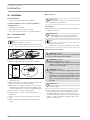
1.1 Safety instructions
1.1.1 Structure of safety instructions
KEYWORD Type of risk
Here, possible consequences are listed that may result
from failure to observe the safety instructions.
Steps to prevent the risk are listed.
1.1.2 Symbols, type of risk
Symbol Type of risk
Injury
Electrocution
Burns
(burns, scalding)
1.1.3 Keywords
KEYWORD Meaning
DANGER Failure to observe this information will result in serious
injury or death.
WARNING Failure to observe this information may result in serious
injury or death.
CAUTION Failure to observe this information may result in non-seri-
ous or minor injury.
1.2 Other symbols in this documentation
Note
Notes are bordered by horizontal lines above and below
the text. General information is identified by the adjacent
symbol.
Read these texts carefully.
Symbol
Material losses
(appliance damage, consequential losses and environmen-
tal pollution)
Appliance disposal
This symbol indicates that you have to do something. The ac-
tion you need to take is described step by step.
1.3 Units of measurement
Note
Unless specified otherwise, all dimensions are given in
mm.
2. Safety
2.1 Intended use
This appliance is intended for domestic use. It can be used safely
by untrained persons. The appliance can also be used in a non-do-
mestic environment, e.g. in a small business, as long as it is used
in the same way.
This appliance is suitable for heating domestic hot water or for
reheating preheated water. The appliance is designed for one
kitchen sink or one washbasin.
Any other use beyond that described shall be deemed inappropri-
ate. Observation of these instructions and of instructions for any
accessories used is also part of the correct use of this appliance.
2.2 General safety instructions
WARNING Burns
During operation, the tap can reach temperatures in ex-
cess of 60 °C.
There is a risk of scalding at outlet temperatures in ex-
cess of 43°C.
!
WARNING Injury
The appliance may be used by children aged 3 and older
and persons with reduced physical, sensory or mental
capabilities or a lack of experience and know-how, pro-
vided that they are supervised or they have been in-
structed on how to use the appliance safely and have
understood the resulting risks. Children must never play
with the appliance. Children must never clean the ap-
pliance or perform user maintenance unless they are
supervised.
WARNING Electrocution
A damaged power cable may only be replaced by a qual-
ified contractor. This is to avoid putting yourself at risk.
!
Material losses
Protect the appliance and tap against frost.
!
!

OPERATION
Appliance description
22 |DCE 11/13| DCE 11/13 RC| DCE 11/13 H www.stiebel-eltron.com
2.3 Test symbols
See type plate on the appliance.
3. Appliance description
The electronically controlled compact instantaneous water heater
maintains a constant outlet temperature up to its output limit,
irrespective of the inlet temperature.
The appliance warms the water directly at the draw-off point, as
soon as you turn on the hot water tap. The short pipe runs ensure
that energy and water losses are minimal.
For the start flow rate, see "Installation/ Specification/ Data
table".
The DHW output depends on the cold water temperature, the
heating output, the flow rate and the set temperature required.
DHW temperature
The DHW outlet temperature can be variably adjusted.
Heating system
The bare wire heating system is suitable for hard and soft water
areas. This heating system has a low susceptibility to scale build-
up. The heating system ensures quick and efficient DHW provision.
Note
The appliance is equipped with an air detector that large-
ly prevents damage to the heating system. If, during op-
eration, air is drawn into the appliance, the heater shuts
down automatically for one minute, thereby protecting
the heating system.
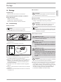
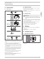
4. Settings
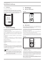
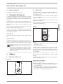
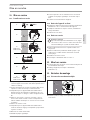
4.1 DCE11/13 | DCE11/13H
Operation
°C
40
50
60
30
20
D0000039989
1
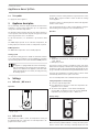
1 Temperature selector: Temperature setting range
20°C– 60°C
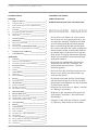
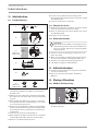
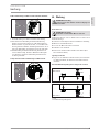
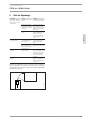
4.2 DCE 11/13 RC
With the wireless remote control, the temperature setting can
be adjusted by wireless control. The selected temperature is dis-
played on the remote control.
The wireless remote control provided is registered to the receiver
module. Only a registered remote control can alter the settings
on the appliance.
The wireless range is reduced by obstacles between the appliance
and the remote control.
You can mount the wireless remote control anywhere using the
wall mounting bracket supplied in the standard delivery.
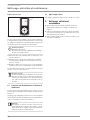
Operation
1
+
-
2
D0000039990
2
1
3
1 Display
2 Temperature selection 20°C – 60°C in 0.5°C steps, using the
+ and - buttons
3 Memory keys 1 and 2
The wireless remote control is normally in power save mode,
which means the display is switched off. Pressing any key activates
the wireless remote control, the temperature display appears. The
progress bar indicates that data is being transmitted to the device.
If no key is pressed within 10seconds the wireless remote control
automatically switches back to power save mode.
The selected temperature is also maintained in power save mode.
Saving temperature to memory keys
Select the required temperature.
Press memory key 1 or 2 for 2seconds. The temperature dis-
play flashes once to confirm.
The heater of the appliance can be switched off (display
message OFF). To switch the heater off, select the minimum
temperature (20°C), then press the "-" button once.
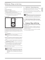
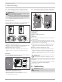
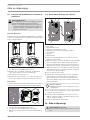
Battery change
1
+
-
2
D0000047484
1
1 Battery change symbol
When the battery symbol illuminates, change the battery of the
wireless remote control. A change of battery may also become

OPERATION
Cleaning, care and maintenance
ENGLISH
www.stiebel-eltron.com DCE 11/13| DCE 11/13 RC| DCE 11/13 H | 23
necessary when the temperature settings are not received by the
device and/or the transmission range decreases.
!
Material losses
Remove the old battery.
Any damage caused by a leaking battery is excluded from
the warranty.
Open the casing of the wireless remote control by unscrew-
ing the 4 screws on the underside of the device.
Replace with a CR2032-type battery. Never use rechargeable
NiCd batteries. Ensure correct polarity of the new battery (+
at the top).
Put the casing back together and re-insert the 4 screws.
When reassembling the casing, do not damage the sealing
gasket.
The stored values for keys 1 and 2 are retained during the battery
change.
Battery disposal
Never dispose of batteries with domestic waste. Spent
batteries contain hazardous substances that are detri-
mental to the environment and human health. Dispose
of batteries through your dealer or via a central recycling
point for special waste.
4.3 Anti-scalding protection/ temperature limit
When activating the anti-scalding protection the DHW temperature
can only be set to between 20°C and 43°C.
Higher temperature settings are not implemented.
Use the anti-scalding protection in locations such as child nurs-
eries, hospitals, care homes etc.
Note
The qualified contractor can activate the anti-scalding
protection in your appliance (see chapter "Installation/
Installation options/ Anti-scalding protection/ Temper-
ature limiter").
4.4 Following an interruption of the water supply
See chapter "Installation/ Commissioning/ Restarting".
5. Cleaning, care and maintenance
Never use abrasive or corrosive cleaning agents. A damp
cloth is sufficient for cleaning the appliance.
Check the taps regularly. Limescale deposits at the tap out-
lets can be removed using commercially available descaling
agents.
Have the electrical safety of the appliance regularly checked
by an electrician.
6. Troubleshooting
Problem Cause Remedy
The appliance will not
start despite the DHW
valve being fully open.
No power at the appli-
ance.
Check the fuse/MCB in
your fuse box/distribu-
tion panel.
The flow rate is too low.
The aerator in the tap is
scaled up or dirty.
Clean and/or descale the
aerator or replace the
special aerator.
The water supply has
been interrupted.
Vent the appliance and
the cold water inlet line
(see chapter "Installa-
tion/ Commissioning/
Restarting").
The required tempera-
ture is not being reached.
Internal anti-scalding
protection is activated.
Ask a qualified contrac-
tor to deactivate the an-
ti-scalding protection.
The appliance is no
longer heating the water,
the cold water inlet tem-
perature >55°C.
Reduce the cold water
inlet temperature.
“Con” occasionally ap-
pears on the display.
The wireless remote con-
trol is outside its range.
Reduce the distance
between the wireless
remote control and the
appliance. Resend the
temperature request.
“Con” frequently appears
on the display.
The battery is at the end
of its capacity.
Change the battery (see
chapter "Operation/
Appliance description/
Battery change").
If you cannot remedy the fault, notify your contractor. To facilitate
and speed up your request, provide the number from the type
plate (000000-0000-000000).
Nr.: 000000-0000-000000
D0000040351

24 |DCE 11/13| DCE 11/13 RC| DCE 11/13 H www.stiebel-eltron.com
INSTALLATION
Safety
INSTALLATION
7. Safety
Only a qualified contractor should carry out installation, commis-
sioning, maintenance and repair of the appliance.
7.1 General safety instructions
We guarantee the trouble-free function and operational reliabil-
ity only if original accessories and spare parts intended for the
appliance are used.
!
Material losses
Observe the maximum permissible inlet temperature (see
chapter "Installation/ Specification/ Data table"). Higher
temperatures may damage the appliance. You can limit
the inlet temperature by means of a central thermostatic
valve (see chapter "Installation/ Appliance description/
Accessories").
7.2 Instructions, standards and regulations
Note
Observe all applicable national and regional regulations
and instructions.
The specific electrical resistance of the water must not fall below
that stated on the type plate. In a linked water network, factor in
the lowest electrical resistance of the water (see chapter "Installa-
tion/ Specification/ Data table"). Your water supply utility will ad-
vise you of the specific electrical water resistance or conductivity.
8. Appliance description
8.1 Standard delivery
The following are delivered with the appliance:
- Plug for cable entry
- Installation template in the centre part of these instructions
- Connection hose 3/8, 500mm long, with gaskets*
- Tee 3/8*
* for connection as pressure-tested appliances DCE11/13 and
DCE11/13RC
8.2 Accessories
Load shedding relay
Priority control can be set up using an electronic load-shedding
relay, in order to separate a second instantaneous water heater
from the mains power supply for example.
The responding current on the load shedding relay must be ≤2A.
It is connected to the central L terminal.
Non-pressurised taps
- WEN sensor tap for washbasins
- MEK mono lever mixer tap
- WKM twin-lever mixer tap
Pressure-tested tap
- WEH sensor tap for washbasins
- MEKD mono lever mixer tap for oversink installation
ZTA 3/4 – Central thermostatic valve
The thermostatic valve is for central premixing, for example when
operating the instantaneous water heater with a solar thermal
system.
9. Preparations
Flush the water line thoroughly.
Water installation
No safety valve is required.
Taps
Use suitable taps (see chapter "Installation/ Appliance de-
scription/ Accessories").
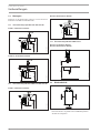
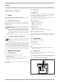
9.1 Installation site
Always install the appliance vertically in a room free from the risk
of frost and near the draw-off point.
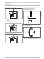
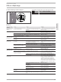
9.1.1 DCE11/13 | DCE11/13RC undersink installation for sink
Non-pressurised, with non-pressurised tap
850
550-600
≈ 600
≥ 70
D0000039998

ENGLISH
www.stiebel-eltron.com DCE 11/13| DCE 11/13 RC| DCE 11/13 H | 25
INSTALLATION
Preparations
Pressure-tested, with pressure-tested tap
850
520 - 570
≈ 600
≥ 70
D0000039997
9.1.2 DCE11/13 | DCE11/13RC undersink installation for
washbasin
Non-pressurised, with non-pressurised tap
850
520-570
≈ 600
≥ 70
D0000040000
Pressure-tested, with pressure-tested tap
850
520 - 570
≈ 600
≥ 70
D0000039999
9.1.3 DCE11/13H oversink installation for washbasin
Non-pressurised with non-pressurised tap
Pressure-tested with pressure-tested tap
850
200-300
D0000050407
9.2 Minimum clearances
≥20≥20
≥50
≥50
D0000060938
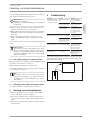
Maintain the minimum clearances to ensure trouble-free op-
eration of the appliance and facilitate maintenance work.

26 |DCE 11/13| DCE 11/13 RC| DCE 11/13 H www.stiebel-eltron.com
INSTALLATION
Installation
10. Installation
Standard installation
- Electrical connection in upper part of appliance
For further installation options, see chapter "Installation/
Installation options":
- Adjustable connected load
- Anti-scalding protection/ temperature limit
- Electrical connection in the lower section of the appliance
10.1 Standard installation
Appliance installation
Note
Mount the appliance on a wall.
The wall must have a sufficient load-bearing capacity.
D0000039991
Undo the snap fastener using a screwdriver.
Remove the appliance front cover by pulling it forwards.
5,5 - 6,5
1
2
D0000039992
1 Upper fixing screw
2 Lower fixing screw
Mark out the 3 holes to be drilled using the installation tem-
plate (see centre section of these instructions).
Drill the holes. Use suitable rawl plugs and round head or
cylinder head screws with 8mm screw head diameter. The
screws and rawl plugs are not part of the standard delivery.
Insert the upper screw to the depth indicated.
Hook the appliance onto the screw. Pull the appliance
downwards.
Tick the selected connected load and voltage on the type
plate.
Align the appliance horizontally. Then insert the lower 2
screws.
Water connection
!
Material losses
For the appliance to function correctly, the strainer must
be built into the cold water inlet.
Tap installation
Install the tap. For this, also observe the tap operating and
installation instructions.
!
Material losses
When making the connections, counter the torque
on the appliance using an appropriate spanner.
Note
Only in the case of pressure-tested connections
DCE11/13| DCE11/13RC:
Fit the 3/8 connection hose and the 3/8 tee provided.
Making the electrical connection
WARNING Electrocution
Carry out all electrical connection and installation work
in accordance with relevant regulations.
WARNING Electrocution
Ensure that the appliance is earthed.
Ensure the appliance can be separated from the power
supply by an isolator that disconnects all poles with at
least 3mm contact separation.
WARNING Electrocution
The appliances are delivered equipped with a power
cable.
Connection to a permanent power supply is possible,
provided the cross-section of the fixed cable is at least
equal to that of the standard power cable for the ap-
pliance. The maximum permissible cross-section is
4x6mm².
!
Material losses
Observe the type plate. The specified voltage must match
the mains voltage.
Connect the power cable in accordance with the electrical
connection diagram (see chapter "Installation/ Specifica-
tion/ Wiring diagram"). There is a choice between 2 con-
nected loads. The high load is preset. If selecting a different
output, see chapter "Installation/Installation options/ Ad-
justable connected load".

ENGLISH
www.stiebel-eltron.com DCE 11/13| DCE 11/13 RC| DCE 11/13 H | 27
INSTALLATION
Commissioning
11. Commissioning
11.1 Initial start-up
1.
2.
4.
3.
5.
6.
≥ 60 s
°C
40
50
60
30
20
°C
40
50
60
30
20
DCE 11/13
DCE 11/13 H
DCE 11/13
DCE 11/13 H
D0000039994
Fill the appliance by running the tap until the pipework and
appliance are free of air. Open the draw-off valve several
times.
Activate the electronic safety switch (AE3). On delivery, the
electronic safety switch is in the tripped position.
Only for the DCE11/13 | DCE11/13H: Insert the temperature
selector plug into the "set temperature" PCB. Note the align-
ment of the wires.
Fit the appliance cover by positioning it and pressing against
it until the locking hooks at the top and bottom click into
place. Check that the locking hooks have clicked into place.
Switch the mains electrical power ON.
Only for the DCE11/13 | DCE11/13H: Turn the temperature
selector to its left-hand and right-hand end-stop.
Carry out a tightness check.
Tick the selected connected load and rated voltage on the
type plate. Use a ballpoint pen to do this.
Check the function of the appliance.
11.2 Appliance handover
Explain the functions of the appliance to the user. Show the
user how to operate the appliance.
Make the user aware of potential dangers, especially the risk
of scalding.
Hand over these instructions.
11.3 Recommissioning
!
Material losses
Following an interruption to the water supply, recommis-
sion the appliance by carrying out the following steps.
This will prevent destruction of the bare wire heating
system.
Disconnect the appliance from the power supply by removing
the fuses/tripping the MCBs.
Open the tap for one minute until the appliance and its up-
stream cold water inlet line are free of air.
Switch the mains electrical power back ON again.
See chapter "Installation/ Commissioning".
12. Shutdown
Disconnect the appliance from the mains at the MCB/fuse in
the fuse box.
Drain the appliance (see chapter "Installation/
Maintenance").
13. Installation options
13.1 Adjustable connected load
13kW
11kW
D0000039993
Plug in the coding card in accordance with the selected con-
nected load.

28 |DCE 11/13| DCE 11/13 RC| DCE 11/13 H www.stiebel-eltron.com
INSTALLATION
Troubleshooting
13.2 Anti-scalding protection/ temperature limit
WARNING Burns
When operating with preheated water, the set anti-scald-
ing protection may be ineffective.
In this case, restrict the temperature at the upstream
central thermostatic valve (see chapter "Installation/
Appliance description/ Accessories").
DCE11/13 | DCE11/13H
The anti-scalding protection "max. 43°C" is activated by reposi-
tioning the plug on the circuit board in the appliance cap.
60 °C
43 °C
D0000039995
1 2
1 Without anti-scalding protection
2 With anti-scalding protection 43°C
Remove the electronic PCB from the programming unit of the
appliance cover. Be careful with the snap-on hooks.
Move the plug to the "43°C" position.
Refit the electronic PCB, ensuring the snap-on hooks click
into place. Observe the positions of the push-button and
shaft.
DCE 11/13 RC
The anti-scalding protection "max. 43°C" is activated by changing
the setting of the DIP switch in the appliance.
60°C
43°C
D0000043533
1
2
4 3
1 DIP switch for anti-scalding protection
2 Without anti-scalding protection = 60°C
3 With anti-scalding protection = max. 43°C
4 Green LED indicator: Permanently illuminated when an-
ti-scalding protection is active
13.3 Conversion for power connection from below
D0000043440
21 3 4 6
25 3 41
7
1 Power cable
2 Cable grommet
3 Strain relief
4 Mains terminal
5 Marker for power cable aperture
6 Plug
7 Wire guides
Remove the strain relief fitting and the power cable with the
cable grommet.
Seal the top opening in the back panel using the enclosed
(sealed) plug. Protection rating IP25 (hoseproof) can only be
guaranteed with a correctly fitted plug.
Reposition the mains terminal in the appliance from the top
to the bottom. Ensure that the mains terminal clicks into
place.
Route the control wires under the wire guide.
Provide an aperture for the power cable at the back of the
appliance. For this, use a suitable tool to apply pressure
along the circular plastic knock-out marking on the appliance
back panel, pushing from the inside out. If necessary, use a
file.
!
Material losses
If the appliance back panel is damaged, replace it.
Fit the power cable with the cable grommet to the appliance
back panel.
Connect the power cable to the mains terminal (see chapter
"Installation/ Specification/ Wiring diagram").
Fit the strain relief.
14. Troubleshooting
WARNING Electrocution
In order to test the appliance it must be connected to the
power supply.

ENGLISH
www.stiebel-eltron.com DCE 11/13| DCE 11/13 RC| DCE 11/13 H | 29
INSTALLATION
Troubleshooting
Troubleshooting
Diagnostic traffic
light
Fault Cause Remedy
No LED illuminates No hot water.
The fuse/MCB in the fuse box has blown/re-
sponded.
Check the fuse/MCB in your fuse box/distribution
panel.
The PCB is faulty. Replace the appliance.
Green LED flashing
The appliance does not start. The shower head / aerators are scaled up. Descale or if necessary replace the shower
head/ aerators.
The DHW flow rate is too low. The strainer in the appliance is dirty. Clean the strainer.
No warm water when flow rate is higher
than starting flow rate.
Flow sensor DFE is faulty. Replace the appliance.
Flashing green LED,
flashing yellow LED
The set temperature is not achieved. The appliance is at its output limit. Reduce the flow rate. Install the flow limiter.
Check the flow limiter.
(not in all cases) The set temperature is not achieved. One phase down. Check the fuse/MCB in your fuse box/distribution
panel.
Green LED flashing,
yellow LED perma-
nently on
The set temperature is not achieved.
The set value transducer or the connecting cable
is faulty. The connecting cable is not plugged in.
Plug in the connecting cable; replace the set
value transducer if required.
Anti-scalding protection is activated. Deactivate the anti-scalding protection.
No warm water when flow rate is higher
than starting flow rate.
The heating system is faulty. Check the resistance of the heating system and
replace the appliance if required.
The PCB is faulty. Replace the appliance.
Set temperature is not achieved. The outlet detector is faulty. Check the connection and replace the outlet de-
tector if required.
Green LED flashing,
red LED flashing fast
No hot water. The appliance is scaled up. Replace the appliance.
The appliance does not respond to the
wireless remote control; "Con" appears
on the display of the wireless remote
control.
The wireless remote control is not registered.
Register the wireless remote control (see
chapter „Installation / Troubleshooting / Re-
gistering / deregistering the wireless remote
control“.
The connecting cable of the wireless remote
control is not plugged in.
Plug in the connecting cable (see chapter "In-
stallation / Troubleshooting").
Green LED flashing,
red LED permanently
on
No hot water.
The safety switch has tripped.
Remove the cause of the fault.
Protect the heating system against overheating
by opening a draw-off valve downstream of the
appliance for one minute. This cools down the
heating system. Activate the safety switch by
pressing the pushbutton on the safety switch
(see also chapter "Installation/ Commission-
ing").
Fault in the electronic safety equipment. Replace the appliance.
The inlet sensor or the connecting cable is
faulty.
Check the connection and replace the inlet sen-
sor if required.
There is a short circuit in the outlet sensor or the
connecting cable.
Check the connection and replace the outlet sen-
sor if required.
The PCB is faulty. Replace the appliance.
Required temperature > 55 °C is not
reached.
The cold water inlet temperature exceeds 55°C. Reduce the cold water inlet temperature to the
appliance.
The heater switches off. The air detector senses air in the water. Heating
output cuts out temporarily.
The appliance restarts after one minute.
Indication options for LED diagnostic traffic light
13kW
11kW
D0000043418
Indication options for diagnostic traffic light (LED)
Red Illuminates in the event of a fault
Yellow Illuminates during heating operation
Green Flashing: Appliance is supplied with
mains power

30 |DCE 11/13| DCE 11/13 RC| DCE 11/13 H www.stiebel-eltron.com
INSTALLATION
Maintenance
Registering/ deregistering the wireless remote control at the
DCE11/13RC
D0000048647
1
2
1 Button for registering and deregistering
2 Yellow LED illuminates when wireless remote control is
activated
To start registration of the wireless remote control briefly
press the button. The yellow LED starts to flash. Now press
key "1" on the wireless remote control. A brief flashing of the
LED indicates that registration was successful. The yellow LED
then extinguishes.
To deregister the wireless remote control press the key for
5seconds. A brief flashing of the LED indicates that deregis-
tration was successful. The yellow LED then extinguishes.
Plug-in position of the wireless remote control for
DCE11/13RC
D0000046810
15. Maintenance
WARNING Electrocution
Before any work on the appliance, disconnect it omnip-
olar from the power supply.
Draining the appliance
WARNING Burns
Hot water may escape during draining.
For maintenance work or when there is a risk of frost, drain the
appliance as follows:
Close the shut-off valve in the cold water inlet pipe.
Open the draw-off valve.
Undo the water connections on the appliance.
Remove the appliance.
Drain the appliance via the water connections (residual water
will remain in the appliance).
Appliance storage
Store the dismantled appliance in a room free from the risk
of frost, as water residues remaining inside the appliance can
freeze and cause damage.
Cleaning or replacing the strainer/flow limiter
D0000040081
1
2
DCE 11/13
DCE 11/13 RC
D0000050374
2
1
DCE 11/13 H
1 Strainer
2 Flow limiter

ENGLISH
www.stiebel-eltron.com DCE 11/13| DCE 11/13 RC| DCE 11/13 H | 31
INSTALLATION
Specication
16. Specification
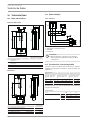
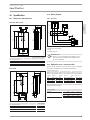
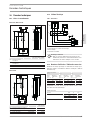
16.1 Dimensions and connections
DCE11/13 | DCE11/13RC
293
188
85
99
35
19
b02
b03
c01
c06
193
291
140
D0000039746
DCE 11/13 DCE 11/13 RC
b02 Entry for cables I
b03 Entry for cables II
c01 Cold water inlet Male thread G 3/8 A G 3/8 A
c06 DHW outlet Male thread G 3/8 A G 3/8 A
DCE 11/13 H
293
85
99
35
19
b02
b03
100
140
c01
c06
193
40
188
D0000050396
DCE 11/13 H
b02 Entry for cables I
b03 Entry for cables II
c01 Cold water inlet Male thread G 1/2 A
c06 DHW outlet Male thread G 1/2 A
16.2 Wiring diagram
3/PE ~ 380-415 V
D0000040233
3
4
1
2
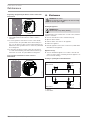
1 High limit safety cut-out
2 Electronic safety switch
3 PCB
4 Heating system
!
Material losses
In the case of a permanent power supply, connect
the power cable according to the designations on
the socket terminals.
16.3 Application areas / conversion table
Specific electrical resistance and specific electrical conductivity
(see chapter "Installation/ Specification/ Data table").
Standard specification at
15°C
20°C
25°C
Spec. re-
sistance
ρ ≥
Spec. conduc-
tivity σ ≤
Spec. re-
sistance
ρ ≥
Spec. conduc-
tivity σ ≤
Spec. re-
sistance
ρ ≥
Spec. conduc-
tivity σ ≤
Ωcm mS/m μS/cm Ωcm mS/m μS/cm Ωcm mS/m μS/cm
900 111 1111 800 125 1250 735 136 1361
1100 91 909 970 103 1031 895 112 1117
Outlet temperature approx. 60°C for the kitchen sink and when
using a thermostatic valve
Outlet volume
Appliance kW 11 13.5
Cold water inlet temperature
6°C l/min 2.9 3.6
10°C l/min 3.2 3.9
14°C l/min 3.4 4.2

32 |DCE 11/13| DCE 11/13 RC| DCE 11/13 H www.stiebel-eltron.com
INSTALLATION
Specication
Ideal temperature of approx. 38°C for hand-washing etc.
Amount of mixed water
Appliance kW 11 13.5
Cold water inlet temperature
6°C l/min 5.0 6.1
10°C l/min 5.7 6.9
14°C l/min 6.6 8.1
Values in the table are relative to a rated voltage of 400 V. The
mixed water volume and outlet volume are subject to the available
supply pressure and the available mains voltage.
16.4 Pressure drop
Taps
Pressure drop at flow rate 10l/min
Mono lever mixer tap, ap-
prox.
MPa 0.04 - 0.08
Thermostatic valve, approx. MPa 0.03 - 0.05
Hand shower, approx. MPa 0.03 - 0.15
Sizing the pipework
When calculating the size of the pipework, a pressure drop for the
appliance of 0.1MPa should be taken into account.
16.5 Fault conditions
In the event of a fault, loads up to a maximum of 80 °C at a pres-
sure of 1.0MPa can occur temporarily in the installation.
16.6 Country-specific approvals and certifications
Test symbols can be seen on the type plate.
16.7 Details on energy consumption
The product data complies with EU regulations relating to the
Directive on the ecological design of energy related products (ErP).
DCE 11/13 DCE 11/13 RC DCE 11/13 H
230770 230771 232792
Manufacturer STIEBEL ELTRON STIEBEL ELTRON STIEBEL ELTRON
Load profile XS XS XS
Energy efficiency class A A A
Annual power consumption kWh 465 465 465
Energy conversion efficiency % 40 40 40
Default temperature setting °C 60 60 60
Sound power level dB(A) 15 15 15
Special information on measuring efficiency Data at Pmax. Data at Pmax. Data at Pmax.

ENGLISH
www.stiebel-eltron.com DCE 11/13| DCE 11/13 RC| DCE 11/13 H | 33
INSTALLATION
Specication
16.8 Data table
DCE 11/13 DCE 11/13 compact RC DCE 11/13 H
230770 230771 232792
Electrical details
Rated voltage V 380 400 415 380 400 415 380 400 415
Rated output kW 10/12,1 11/13,5 11,8/14,5 10/12,1 11/13,5 16,8/20,2 10/12,1 11/13,5 11,8/14,5
Rated current A 15,4/18,5 16,2/19,5 16,8/20,2 15,4/18,5 16,2/19,5 16,4/20,1 15,4/18,5 16,2/19,5 16,8/20,2
MCB/fuse rating A 16/20 16/20 16/20 16/20 16/20 16/20 16/20 16/20 16/20
Phases 3/PE 3/PE 3/PE
Frequency Hz 50/60 50/60 50/- 50/60 50/60 50/- 50/60 50/60 50/-
Specific resistance ρ
15
≥ (at ϑcold ≤25°C) Ω cm 900 900 900 900 900 900 900 900 900
Specific resistance σ
15
≤ (at ϑcold ≤25°C) μS/cm 1111 1111 1111 1111 1111 1111 1111 1111 1111
Specific resistance ρ
15
≥ (at ϑcold ≤55°C) Ω cm 1100 1100 1100 1100 1100 1100 1100 1100 1100
Specific conductivity σ
15
≤ (at ϑcold ≤55°C) μS/cm 909 909 909 909 909 909 909 909 909
Max. mains impedance at 50Hz Ω 0,28 0,26 0,24 0,28 0,26 0,24 0,28 0,26 0,24
Electronic standby W < 2 < 2 < 2
Connections
Water connection G 3/8 A G 3/8 A G 1/2 A
Application limits
Max. permissible pressure MPa 1 1 1
Max. inlet temperature for reheating °C 55 55 55
Values
Max. permissible inlet temperature °C 70 70 70
ON l/min >2,5 >2,5 >2,5
Flow rate for pressure drop l/min 4 4 4
Pressure drop at flow rate MPa 0,06 0,06 0,07
Pressure drop at flow rate without flow limiter MPa 0,015 0,015 0,025
Flow rate limit at l/min 4 4 4
DHW delivery l/min 3,7/4,5 3,7/4,5 3,7/4,5
Δϑ at DHW delivery K 43 43 43
Hydraulic data
Rated capacity l 0,2 0,2 0,2
Versions
Undersink installation X X
Oversink installation X
Connected load options X X X
Temperature adjustment °C 20-60 20-60 20-60
Protection class 1 1 1
Insulation block Plastic Plastic Plastic
Heating system heat generator Bare wire Bare wire Bare wire
Cap and back panel Plastic Plastic Plastic
IP-Rating IP24 IP24 IP24
Colour white white white
Dimensions
Height mm 293 293 293
Width mm 188 188 188
Depth mm 99 85 99
Weights
Weight kg 2,5 2,5 2,5

34 |DCE 11/13| DCE 11/13 RC| DCE 11/13 H www.stiebel-eltron.com
INSTALLATION | GUARANTEE | ENVIRONMENT AND RECYCLING
GUARANTEE
ENVIRONMENT AND RECYCLING
Mini wireless remote control
Application limits
Temperature setting range °C 20-60
Wireless frequency EU MHz 868.3
Frequency band MHz 863.000 - 863.600
Wireless range inside the building
approx.
m 25
Versions
IP rating IPX7
Battery type CR2032-3V
Dimensions
Height mm 132
Width mm 65
Depth mm 18.5
Weights
Weight kg 0.12
Note
The wireless range is dependent on the building char-
acteristics. Function through a separating ceiling cannot
always be guaranteed.
Guarantee
The guarantee conditions of our German companies do not
apply to appliances acquired outside of Germany. In countries
where our subsidiaries sell our products a guarantee can only
be issued by those subsidiaries. Such guarantee is only grant
-
ed if the subsidiary has issued its own terms of guarantee. No
other guarantee will be granted.
We shall not provide any guarantee for appliances acquired in
countries where we have no subsidiary to sell our products.
This will not aect warranties issued by any importers.
Environment and recycling
We would ask you to help protect the environment.
After use,
dispose of the various materials in accordance with national
regulations.
INSTALLATION TEMPLATE (IN THE MIDDLE OF THESE INSTRUCTIONS)

FRANÇAIS
www.stiebel-eltron.com DCE 11/13| DCE 11/13 RC| DCE 11/13 H | 35
TABLE DES MATIÈRES | REMARQUES PARTICULIÈRES
REMARQUES PARTICULIÈRES
UTILISATION
1. Remarques générales ������������������������������������� 36
1.1 Consignes de sécurité ������������������������������������������ 36
1.2 Autres symboles utilisés dans cette documentation �����36
1.3 Unités de mesure ����������������������������������������������� 36
2. Sécurité ����������������������������������������������������� 36
2.1 Utilisation conforme �������������������������������������������36
2.2 Consignes de sécurité générales ���������������������������� 36
2.3 Label de conformité �������������������������������������������� 37
3. Description de l’appareil ���������������������������������� 37
4. Réglages ���������������������������������������������������� 37
4.1 DCE11/13 | DCE11/13H ������������������������������������� 37
4.2 DCE 11/13 RC ���������������������������������������������������� 37
4.3 Protection anti-ébouillantement/ limitation de
température �����������������������������������������������������38
4.4 Après coupure d’eau ������������������������������������������� 38
5. Nettoyage, entretien et maintenance �������������������� 38
6. Aide au dépannage ���������������������������������������� 39
INSTALLATION
7. Sécurité ����������������������������������������������������� 40
7.1 Consignes de sécurité générales ����������������������������40
7.2 Réglementations, normes et directives ��������������������40
8. Description de l’appareil ���������������������������������� 40
8.1 Fournitures�������������������������������������������������������40
8.2 Accessoires �������������������������������������������������������40
9. Travaux préparatoires ������������������������������������� 40
9.1 Lieu d’implantation���������������������������������������������40
9.2 Distances minimales ������������������������������������������� 41
10. Montage ����������������������������������������������������� 42
10.1 Pose standard ��������������������������������������������������� 42
11. Mise en service ��������������������������������������������� 43
11.1 Première mise en service �������������������������������������43
11.2 Remise de l’appareil au client �������������������������������� 43
11.3 Remise en service ����������������������������������������������43
12. Mise hors service ������������������������������������������ 43
13. Variantes de montage ������������������������������������� 43
13.1 Puissance de raccordement multiple ����������������������� 43
13.2 Protection anti-ébouillantement/ limitation de
température �����������������������������������������������������44
13.3 Raccordement électrique par le dessous ������������������44
14. Aide au dépannage ���������������������������������������� 44
15. Maintenance ������������������������������������������������ 46
16. Données techniques ��������������������������������������� 47
16.1 Cotes et raccordements ���������������������������������������� 47
16.2 Schéma électrique ���������������������������������������������� 47
16.3 Domaines d’utilisation/ Tableau de conversion ���������� 47
16.4 Pertes de charge ������������������������������������������������ 48
16.5 Conditions en cas de panne ����������������������������������48
16.6 Homologations et certificats spécifiques au pays �������� 48
REMARQUES
PARTICULIÈRES
- L’appareil peut être utilisé par des enfants dès
l’âge de 3 ans ainsi que par des personnes aux
facultés physiques, sensorielles ou mentales
réduites ou par des personnes sans expérience
sous surveillance ou après formation à l’utilisa-
tion en toute sécurité de l’appareil si les dangers
potentiels ont été compris. Ne laissez pas les en-
fants jouer avec l’appareil. Ni le nettoyage ni la
maintenance relevant de l’utilisateur ne doivent
être effectués par des enfants sans surveillance.
- Pendant le fonctionnement, la température de la
robinetterie peut dépasser 60°C. Danger de brû-
lures à des températures de sortie supérieures à
43°C.
- L’appareil doit pouvoir être déconnecté du secteur
par un dispositif de coupure omnipolaire ayant
une ouverture minimale des contacts de 3 mm.
- En cas de détérioration ou de changement du
câble d’alimentation, celui-ci doit uniquement
être remplacé par une pièce de rechange d’ori-
gine, par un installateur habilité par le fabricant.
- Fixez l’appareil comme indiqué au chapitre «Ins-
tallation/ Montage».
- Tenez compte de la pression admissible maxi-
male (voir chapitre «Installation/ Données tech-
niques/ Tableau de données»).
- Vidangez l’appareil comme indiqué au cha-
pitre «Installation/ Maintenance/ Vidange de
l’appareil».
16.7 Indications relatives à la consommation énergétique ���48
16.8 Tableau de données �������������������������������������������� 49
GARANTIE
ENVIRONNEMENT ET RECYCLAGE
GABARIT DE MONTAGE (EN PAGE CENTRALE DE CETTE NOTICE)
Page is loading ...
Page is loading ...
Page is loading ...
Page is loading ...
Page is loading ...

FRANÇAIS
www.stiebel-eltron.com DCE 11/13| DCE 11/13 RC| DCE 11/13 H | 41
INSTALLATION
Travaux préparatoires
Sous pression, avec robinetterie sous pression
850
520 - 570
≈ 600
≥ 70
D0000039997
9.1.2 Montage sous évier - Lavabo DCE11/13 | DCE11/13RC
Écoulement libre, avec robinetterie à écoulement libre
850
520-570
≈ 600
≥ 70
D0000040000
Sous pression, avec robinetterie sous pression
850
520 - 570
≈ 600
≥ 70
D0000039999
9.1.3 Montage sur évier - Lavabo DCE11/13H
Écoulement libre, avec robinetterie à écoulement libre
Sous pression, avec robinetterie sous pression
850
200-300
D0000050407
9.2 Distances minimales
≥20≥20
≥50
≥50
D0000060938
Respectez les distances minimales de sorte à assurer un
fonctionnement sans incident et de faciliter les travaux de
maintenance.
Page is loading ...
Page is loading ...
Page is loading ...
Page is loading ...
Page is loading ...
Page is loading ...
Page is loading ...
Page is loading ...
Page is loading ...
Page is loading ...
-
 1
1
-
 2
2
-
 3
3
-
 4
4
-
 5
5
-
 6
6
-
 7
7
-
 8
8
-
 9
9
-
 10
10
-
 11
11
-
 12
12
-
 13
13
-
 14
14
-
 15
15
-
 16
16
-
 17
17
-
 18
18
-
 19
19
-
 20
20
-
 21
21
-
 22
22
-
 23
23
-
 24
24
-
 25
25
-
 26
26
-
 27
27
-
 28
28
-
 29
29
-
 30
30
-
 31
31
-
 32
32
-
 33
33
-
 34
34
-
 35
35
-
 36
36
-
 37
37
-
 38
38
-
 39
39
-
 40
40
-
 41
41
-
 42
42
-
 43
43
-
 44
44
-
 45
45
-
 46
46
-
 47
47
-
 48
48
-
 49
49
-
 50
50
-
 51
51


STIEBEL ELTRON DCE 11/13 H Operation and Installation
- Type
- Operation and Installation
- This manual is also suitable for
Ask a question and I''ll find the answer in the document
Finding information in a document is now easier with AI
in other languages
- français: STIEBEL ELTRON DCE 11/13 H
- Deutsch: STIEBEL ELTRON DCE 11/13 H
Related papers
-
STIEBEL ELTRON DHB-E SLi Electronic Control Instantaneous Water Heater User manual
-
-
-
-
-
STIEBEL ELTRON DNM 4 Operation and Installation
-
-
-
-
Other documents
-
Soundmaster C250DVD Datasheet
-
AEG MTE 570 Operation and Installation
-
Atlantic VISIO Series Quick start guide
-
-
Siemens DE18115/01 User manual
-
Kospel EPS2.P User manual
-
Vox WHSM35-50-65-80-100 User manual
-
-
-
Austria Email DEX27 KW Operating instructions