
wwf
Pre-Installation Notes
Note
• Due to ongoing research and product development, specifications, ratings, and dimensions are
subject to change without notice. Refer to www.LIFEBREATH.com for the latest product
information.
Attention
• Do not apply electrical power to the unit until after the completion of the installation (including
installation of low voltage control wiring).
• Ensure the installation and wiring is in accordance with CEC, NEC, and local electrical codes.
• Plug the unit into a standard designated (120 VAC) electrical outlet with ground.
• The use of an extension cord with this unit is not recommended. If the installation requires
further wiring, have a licensed electrician make all of the electrical connections. The
recommended circuit is a separate 15 A/120 V circuit.
Caution
• Before installation, careful consideration must be given to how this system will operate if
connected to any other piece of mechanical equipment, i.e. a forced air furnace or air handler,
operating at a higher static. After installation, the compatibility of the two pieces of equipment
must be confirmed, by measuring the airflows of the HRV, by using the balancing procedure
found in this manual. Never install a ventilator in a situation where its normal operation, lack of
operation or partial failure may result in the back drafting or improper functioning of vented
combustion equipment
• Unit must be installed level to ensure proper condensate drainage. Due to the broad range of
installation and operational conditions, consider the possibility of condensation forming on
either the unit or connecting ducting. Objects below the installation may be exposed to
condensate.
• Do not install control wiring alongside electrical wire.
Warning

www.lifebreath.com 2
Pre-Installation Notes
Note
• Due to ongoing research and product development, specifications, ratings, and dimensions are
subject to change without notice. Refer to www.lifebreath.com for the latest product
information.
Attention
• Do not apply electrical power to the unit until after the completion of the installation (including
installation of low voltage control wiring).
• Ensure the installation and wiring is in accordance with all local electrical codes.
• Plug the unit into a standard designated (120 VAC) electrical outlet with ground.
• The use of an extension cord with this unit is not recommended. If the installation requires
further wiring, have a licensed electrician make all the electrical connections. The
recommended circuit is a separate 15 A/120 V circuit.
Caution
• Before installation, careful consideration must be given to how this system will operate if
connected to any other piece of mechanical equipment, i.e. a forced air furnace or air handler,
operating at a higher static. After installation, the compatibility of the two pieces of equipment
must be confirmed, by measuring the airflows of the HRV, by using the balancing procedure
found in this manual. Never install a ventilator in a situation where its normal operation, lack of
operation or partial failure may result in the back drafting or improper functioning of vented
combustion equipment
• Unit must be installed level to ensure proper condensate drainage. Due to the broad range of
installation and operational conditions, consider the possibility of condensation forming on
either the unit or connecting ducting. Objects below the installation may be exposed to
condensate.
• Do not install control wiring alongside electrical wire.
Warning
• Disconnect the power from the unit before cleaning or servicing.
• To prevent electrical shock, it is extremely important to confirm the polarity of the power line
that is switched by the safety (disconnect) switch. The hot line (black) is the proper line for
switching. Use either a voltmeter or test lamp to confirm the absence of a voltage between the
disconnect switch and ground (on the cabinet) while the door is open. This procedure must be
followed, as dwellings are occasionally wired improperly. Always ensure the proper grounding
of the unit.
• Improper installation, adjustment, alteration, service, or maintenance can cause property
damage, personal injury or loss of life. Installation and service must be performed by a
qualified installer or service agency.

www.lifebreath.com 3
Table of Contents
1 Location Notes ........................................................ 4
2 Simplified Installation (Return/Return Method) ..... 5
3 Partially Dedicated System Installation .................. 6
4 Fully Dedicated System Installation ........................ 7
5 Optional Duct Configurations (195DCS) .................. 8
6 Mounting (RNC4-TPD / -TPF) .................................. 9
7 Hanging Straps ...................................................... 10
8 Drain Connection .................................................. 11
9 Grilles .................................................................... 12
10 Grille Fittings ..................................................... 13
11 Lifebreath Weather Hoods ................................ 14
12 Lifebreath Dual Hood ........................................ 15
13 Main Control Installation (99-DXPL02) ............. 16
14 Main Control Installation (99-BC02/3/4) .......... 17
15 Interlocking the HRV ......................................... 18
16 Additional Controls ........................................... 19
17 Timers ................................................................ 20
17 Timers ................................................................ 21
18 Repeater ............................................................ 22
19 Installer Selectable High Speed Settings ........... 23
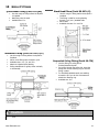
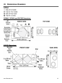
20 Dimensional Drawings ...................................... 24
20 Dimensional Drawings ...................................... 25
21 Dimensional Drawings ...................................... 26
22 Balancing the Airflows ...................................... 27
23 Balancing the Airflows ...................................... 28
24 Balancing the Airflows – Pitot Tube .................. 29
25 Balancing the Airflows – Door Ports ................. 30
26 Door Port Locations .......................................... 31
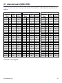
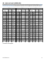
27 Airflow Charts (RNC4-TPD) ............................... 32
26 Airflow Charts (RNC4-TPD) ............................... 33
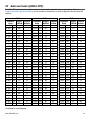
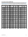
27 Airflow Charts (RNC4-TPF) ................................ 34
27 Airflow Charts (RNC4-TPF) ................................ 35
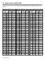
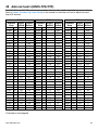
28 Airflow Charts (RNC6-ES) .................................. 36
28 Airflow Charts (RNC6-ES) .................................. 37
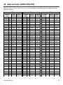
29 Airflow Charts (RNC5-TPD/TPF) ........................ 38
29 Airflow Charts (RNC5-TPD/TPF) ........................ 39
30 Airflow Charts (RNC6-HEX-TPD/5-HEX-TPF) ..... 40
30 Airflow Charts (RNC6-HEX-TPD/5-HEX-TPF) ..... 41
31 Airflow Charts (RNC155 2019) .......................... 42
31 Airflow Charts (RNC155 2019) .......................... 43
31 Airflow Charts (RNC155 2019) .......................... 44
32 Airflow Charts (RNC200) ................................... 45
33 Airflow Charts (RNC205) ................................... 46
33 Airflow Charts (RNC205) ................................... 47
34 Airflow Charts (155 MAX 2019) ........................ 48
35 Airflow Charts (205MAX) .................................. 49
36 Airflow Charts (205MAX) .................................. 50
37 Airflow Charts (267MAX) .................................. 51
37 Airflow Charts (267MAX) .................................. 52
38 Troubleshooting ................................................ 53
39 Troubleshooting ................................................ 54
Homeowners Warranty Information
After the installation is complete, fill out the Warranty Information page in the Homeowner’s manual.

www.lifebreath.com 4
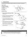
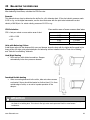
1 LOCATION NOTES
Install the unit in a heated space that provides clearance for service access. A typical location is in
either a mechanical room or an area close to the outside wall within proximity to where the weather
hoods are mounted. If a basement area is inconvenient or non-existent, install the unit in a utility
room or laundry room.
Leave enough clearance at the front of the access door for servicing the air filters and core. The
recommended clearance is a minimum of 25 in. (635 mm) for opening and closing the door. Four
straps are provided with the unit for hanging it from the basement floor joists.
Attic installations are not recommended due to:
• The complexity of work to install
• Difficulty of access for servicing and cleaning
• Freezing conditions in the attic
If attic installation is necessary, the unit must be situated in a conditioned space.
Note: ENERGY STAR
®
If the unit is certified ENERGY STAR
®
, the following applies:
• This product earned the ENERGY STAR
®
by meeting strict energy efficiency guidelines set by
Natural Resources Canada and the US EPA. This product meets ENERGY STAR
®
requirements
only when used in Canada.
• To ensure quiet operation of the ENERGY STAR
®
certified H/ERV, each product model must be
installed using sound attenuation techniques appropriate for the installation.
• The way your heat/energy-recovery ventilator is installed can make a significant difference to
the electrical energy you use. To minimize the electricity use of the heat/energy-recovery
ventilator, a stand-alone fully ducted installation is recommended. If you choose a simplified
installation that operates your furnace air handler for room-to-room ventilation, an electrically
efficient furnace that has an electronically commutated (EC) variable speed blower motor will
minimize your electrical energy consumption and operating cost.
• Installation of a user-accessible control with your product model will improve comfort and may
significantly reduce the product model’s energy use.

www.lifebreath.com 5
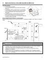
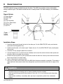
2 SIMPLIFIED INSTALLATION (RETURN/RETURN METHOD)
Installation Notes:
• The HRV must be balanced.
• Unit should be balanced on high speed with the furnace
blower on.
• It is mandatory that the furnace blower run continuously
or HRV operation be interlocked with the furnace blower.
• The duct configuration may change depending on the
HRV model.
• A backdraft damper is recommended in the exhaust air
duct to prevent outdoor air from entering the unit.
• The airflow must be confirmed on site using the balancing
procedures found in this guide.
Spring-Loaded Backdraft Damper (recommended):
Install the Backdraft Damper with the leaf hinge vertical. The damper is installed on the “Stale Air to Outside”
Collar.
Warning
• Check local codes/authority having jurisdiction for acceptance.
• Applications such as greenhouses, atriums, swimming pools, saunas, etc. have unique ventilation
requirements which should be addressed with an isolated ventilation system.
• Weatherhood arrangement is for drawing purposes only. Check local codes/authority having
jurisdiction for acceptance.
• Backdraft dampers are recommended for the stale air to outside air duct. This damper prevents
outdoor air from entering the HRV during the operation of the furnace/air handler while the HRV is in
standby, off, or recirculating.

www.lifebreath.com 6
3 PARTIALLY DEDICATED SYSTEM INSTALLATION
Installation Notes:
• The HRV must be balanced.
• Unit should be balanced on high speed with the furnace
blower on.
• It is recommended that the furnace blower run
continuously or HRV operation be interlocked with the
furnace blower. Refer to building code.
• The duct configuration may change depending on the
HRV model.
• A backdraft damper is recommended in the exhaust air
duct to prevent outdoor air from entering the unit.
• The airflow must be confirmed on site using the
balancing procedures found in this guide.
Spring-Loaded Backdraft Damper (recommended):
Install the Backdraft Damper with the leaf hinge vertical. The damper is installed on the “Stale Air to Outside”
Collar.
Warning
• Check local codes/authority having jurisdiction for acceptance.
• Applications such as greenhouses, atriums, swimming pools, saunas, etc. have unique ventilation
requirements which should be addressed with an isolated ventilation system.
• Weatherhood arrangement is for drawing purposes only. Check local codes/authority having
jurisdiction for acceptance.
• Backdraft dampers are recommended for the stale air to outside air duct. This damper prevents
outdoor air from entering the HRV during the operation of the furnace/air handler while the HRV is
in standby, off, or recirculating.

www.lifebreath.com 7
4 FULLY DEDICATED SYSTEM INSTALLATION
Installation Notes:
• The HRV must be balanced.
• When balancing, all external exhaust systems should be
turned off (i.e. range hood, exhaust, bathroom vents).
• All exhausting appliances should have their own make-up
air, as this is not an intended use for the HRV system.
• The duct configuration may change depending on the
HRV model.
• The airflow must be confirmed on site using the balancing
procedures found in this guide.
Spring-Loaded Backdraft Damper (recommended):
There is a location for an optional Backdraft Damper with the leaf hinge vertical. The damper is installed on
the “Stale Air to Outside” Collar.
Warning
• Check local codes/authority having jurisdiction for acceptance.
• Applications such as greenhouses, atriums, swimming pools, saunas, etc. have unique ventilation
requirements which should be addressed with an isolated ventilation system.
• Weatherhood arrangement is for drawing purposes only. Check local codes/authority having
jurisdiction for acceptance.
• Backdraft dampers are recommended for the stale air to outside air duct. This damper prevents
outdoor air from entering the HRV during the operation of the furnace/air handler while the HRV is
in standby, off, or recirculating.

www.lifebreath.com 8
5 OPTIONAL DUCT CONFIGURATIONS (195DCS)
Note: DIP Switch #2 must be set to “ON” position to activate recirculation if this configuration is applied. See
Installer Selectable High Speed Settings for more information.
Note: DIP Switch #2 must be set to “ON” position to activate recirculation if this configuration is applied. See
Installer Selectable High Speed Settings for more information.
Attention
• Use Figure A ducting configuration to make a non-recirculating defrost unit operate as a recirculating
defrost unit.
Attention
• Use Figure B ducting configuration to avoid negative pressure from being built up in the mechanical
room during the defrost cycle.
Figure A
Figure B

www.lifebreath.com 9
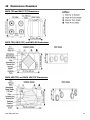
6 MOUNTING (RNC4-TPD / -TPF)
Mounting the RNC4-TPD and RNC4-TPF:
(1) Mounting Points
1. Locate the four mounting tabs on the left and right sides of the unit, at the front and back.
2. Using a flat head screwdriver, bend out the four tabs to approximately 45 degrees.
3. Once the tabs have all been bent outwards, insert the “S” hooks through the four holes on the tabs.
4. Install the unit to the structure. Refer to Hanging Straps.
Attention
• Do not drill additional holes in the HRV

www.lifebreath.com 10
7 HANGING STRAPS
The hanging straps are designed to reduce the possibility of noise, resonance, and harmonics.
Figure Callouts:
(1) Screws (not included)
(2) Washers (not included)
(3) Hanging Strap Grommets
(4) Structure
(5) Machine Screws
(6) “S” Hooks
(7) Hand Loops
Installation Steps:
1. Insert 4 screws and 4 washers (not included)
through the hanging strap grommets. Fasten
to the structure.
2. Remove the 4 machine screws located on the
upper side of the unit. Attach the “S” hooks
and reinsert the machine screws.
3. Hook the bottom grommets of the straps
through the “S” hooks. Pull down vertically
on the hand loops while lifting the bottom of
the unit.
4. Level the unit from right to left to right and
front to back. Adjust the unit up by pulling
down vertically on the hand loops while
lifting on the bottom of the cabinet.
5. Fold the excess strap of the hand loops and
secure with a zip tie.
Attention
• The washer must be wider than the eyelet of the grommet on the hanging strap.
• Must push up on the bottom of the HRV when pulling the hanging straps.
• The unit must be mounted level for proper drainage of the condensate pans.

www.lifebreath.com 11
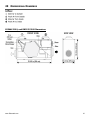
8 DRAIN CONNECTION
The HRV cabinet has pre-punched holes for the drain. The HRV may produce some condensation
during a defrost cycle. This water should flow into a nearby drain or be taken away by a condensate
pump.
Figure Callouts:
(1) Drain Spout
(2) Drain Pan
(3) Nut
(4) Tee Connector
(5) 1/2 in. Drain Hose
(6) Drain Line
(7) Zip Tie
Installation Steps:
1. Insert the drain spout through the hole in the drain pan. For the RCN4-TPD/TPF units, use the drain
spout with the foam gasket only.
2. Install nut and washer on the drain spout. Tighten the nut. For the RCN4-TPD/TPF units, hand-tighten
the nut only.
3. Construct a P-trap using the plastic tee connector.
4. Cut two lengths of 1/2 in. drain hose (not included) and connect the ends to the two drain spouts and
the other ends to the plastic tee connector.
5. Position the tee connector to point upward and connect the drain line. Use a zip tie to secure the drain
line to one of the 1/2 in. drain hoses.
6. Tape or fasten base to avoid any kinks.
7. Pour a cup of water into the drain pan of the HRV after the drain connection is complete. This creates a
water seal which will prevent odours from being drawn up the hose and into the fresh air supply of the
HRV.
Caution
• The HRV and all condensate lines must be installed in a space where the temperature is
maintained above the freezing point or freeze protection must be provided.
• Drain trap and tubing must be below bottom of door with 1/4 in. per foot downwards slope away
from unit.
• Under certain conditions, a secondary drain pan may be required to protect from condensate
leakage.

www.lifebreath.com 12
9 GRILLES
Installation Notes:
Adjustable grilles should be used to balance the flow rates into and out of various rooms. The grilles
should not be adjusted after balancing the unit.
Grilles or diffusers should be positioned high on the wall or in the ceiling. Kitchen exhaust should
never be connected to the range hood. They should be installed at least 4 ft (1.2 m) horizontally
away from the stove.
Field supplied balancing dampers should be installed external to the unit to balance the amount of
stale air being exhausted with the amount of fresh air being brought into the house. Refer to airflow
balancing section.
The Kitchen Grille
The Kitchen Grille includes a removable grease
filter. Most building codes require that kitchen
grilles are equipped with washable filters.
• Part# 99-10-002, 6 in x 10 in
The TechGrille
The TechGrille is a round, fully adjustable grille, which provides quiet air distribution.
• Part # 99-EAG4, 4 in (100 mm)
• Part # 99-EAG5, 5 in (125 mm)
• Part # 99-EAG6, 6 in (150 mm)
• Part # 99-EAG8, 8 in (200 mm)

www.lifebreath.com 13
10 GRILLE FITTINGS
Caution
• Do not mount exhaust grille within 4 ft (1.2 m) (horizontally) of a stove to prevent grease from entering the
unit.
Quick Mount Fitting (Part# 99-QM6)
• Use this rough-in fitting before the drywall
is installed.
• Nail fitting onto the stud.
• Available size: 6 in.
Terminator Fitting (Part# 99-TM 4/5/6)
• Use this rough-in fitting before the drywall is
Installed.
• Nail or screw fitting onto the stud or joist.
• Available sizes: 4 in, 5 in, and 6 in.
• Adapts to ridged and flex ducting
• Strong attachment for grilles, either vertically
or horizontally.
Stack Head Elbow (Part# 99-WF 4/6)
• Use this rough-in fitting before the drywall is
installed.
• This fitting is ideal for running ducting
through 2 x 4 (min.) studded walls.
• Nail to stud.
• Available sizes are 4 in. and 6 in.
Suspended Ceiling Fitting (Part# 99-CF6)
• Use this fitting for ceiling tiles or
finished/installed drywall.
• Cut a hole through the ceiling tile, insert the
fitting and use the retaining ring to hold the
fitting in place.
• For finished/installed drywall, use caulking
around the lip if you do not have access to
attach the retaining ring.
• Available size: 6 in.

www.lifebreath.com 14
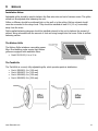
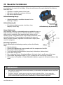
11 LIFEBREATH WEATHER HOODS
Fixed covered weather hoods have a built-in bird screen with a 1/4 in. (6 mm) mesh to prevent foreign objects
from entering the ductwork.
Installation Notes:
• The inner and outer liners of the flexible insulated duct must be clamped to the sleeve of the
weatherhoods (as close to the outside as possible) and the appropriate port on the HRV. It is very
important that the fresh air intake line be given special attention to make sure it is well sealed. A good
bead of high-quality caulking (preferably acoustical sealant) will seal the inner flexible duct to both the
HRV port and the weatherhood prior to clamping.
• The flexible insulated duct that connects the two outside weatherhoods to the HRV should be stretched
tightly and be as short as possible to minimize air flow restrictions.
• Twisting or folding the duct will severely restrict airflow.
• Hard (rigid) ducting which has been sealed and insulated should be used for runs over 10 ft (3.3 m).
Refer to your local building code.
Installation Steps:
1. Thermal collar slides over galvanized sleeve to ensure vapor barrier is 100% sealed to wall plate.
2. Fasten thermal collar to belt.
3. Slide the insulated flexible ducting over galvanized sleeve and fasten it to the thermal collar.
4. Weatherhood is hinged to allow for easy access for cleaning of mesh screen.
Attention
• Weather Hood Requirements: Check local codes/authority having jurisdiction for acceptance and
space requirements for weatherhoods. Do not locate in garage, attic, or crawl space.
i) Intake: Should be located upstream (if there are prevailing winds) from the exhaust outlet. Not
near dryer vents, furnace exhaust, driveways, oil fill pipes, gas meters, or garbage containers.
ii) Exhaust: Not near a gas meter, electric meter or a walkway where fog or ice could create a
hazard.
Figure Callouts:
(1) Thermal Collar
(2) 12 in. long Galvanized Sleeve
(3) Exterior Wall
(4) 1/4 in. (6mm) Mesh Screen

www.lifebreath.com 15
12 LIFEBREATH DUAL HOOD
The Lifebreath Duel Hood only requires one 6 in. opening for intake and exhaust. The Lifebreath Dual
Hood can be used up to a maximum airflow of 140 cfm.
Available Units:
• 99-194 – 4 in. Dual Hood (not shown)
• 99-190 – 5-6 in. Dual Hood
Caution
• Sealant must be applied as per instructions or leakage and condensation may occur.
• Insulate the Fresh Air Supply and Stale Air Exhaust duct work back to the unit.
Attention
• Contact your local building authority before installation of the Dual Hood to verify compliance with
local building codes.
Note
• Tested by: National Research Council Canada
• Program: Building Regulations for Market Access Report Number: A1-007793
• Report Date: 15 February 2016
• Found to comply with requirement as set in the NBC.

www.lifebreath.com 16
13 MAIN CONTROL INSTALLATION (99-DXPL02)
The 99-DXPL02 main control must be surface mounted onto a wall. Only one main control should be installed into a
ventilation system.
Installation:
1. Remove the operating instructions
card from the top of the main control
(figure A).
2. Carefully separate the face plate and
the back plate by firmly pulling it apart
(figure A).
3. Position the back plate of the control
in the desired location on the wall and
mark the wall for the desired screw
holes (figure B).
4. Remove the back plate from the wall
and mark the hole for the wires in
between the two screw holes (figure
B).
5. Drill two holes for the screws and wall
anchors and drill one hole for the wires
in between the two screw holes (figure
B).
6. Pull the 3 wire 20 gauge (min.), 100 ft
length (max.), through the opening in
the wall.
7. Connect the wires to the R, G, and Y
terminals on the back plate (figure B).
8. Using the two supplied screws and
anchors, install the back plate on the
wall.
9. Attach the face plate to the back plate
(figure A).
10. Install the operating instructions card
in the top of the main control (figure
A).
11. Connect the 3 wire 20 gauge (min.), 100 ft length (max.), to the 3 (RED), 4 (YEL), and 5 (GRN) terminals located on
the HRV terminal block (figure C).
Attention
• Use care when separating or attaching the face plate to avoid damaging the contact pins.

www.lifebreath.com 17
14 MAIN CONTROL INSTALLATION (99-BC02/3/4)
The 99-BC02, 99-BC03, 99-BC04 ventilation controls may either be installed onto a flush mounted electrical switch box or
surface mounted onto a wall. Only one main control should be installed into a ventilation system.
Installation:
1. Carefully separate the face plate
and the back plate by firmly
pulling it apart. Keep the
top/bottom vent openings clear
(figure A).
2. Position the back plate in the
desired location on the wall and
mark the wall for the desired
screw holes (figure B).
3. For mounting the main control
without a Decora plate, break off
the top and bottom tabs than
position the back plate in the
desired location on the wall and
mark the wall for the desired
screw holes (figure C)
4. Remove the back plate from the
wall and mark the hole for the
wires centered between the two
screw holes (figure B or C).
5. Drill two 1/8 in. holes for the
screws and wall anchors and drill
one 1 in. x 0.75 in. hole for the
wires.
6. Pull the 3 wire 20 gauge (min.),
100 ft length (max.), through the
opening in the wall.
7. Connect the wires to the R, G, and
Y terminals on the back plate
(figure B or C).
8. Using the two supplied screws and
anchors, install the back plate on
the wall.
9. Attach the face plate to the back
plate (figure A).
10. Connect the 3 wire 20 gauge (min.), 100 ft length (max.), to the 3 (RED), 4 (YEL), and 5 (GRN) terminals located on
the HRV terminal block (figure D).
Attention
• Use care when separating or attaching the face plate to avoid damaging the contact pins.

www.lifebreath.com 18
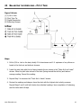
15 INTERLOCKING THE HRV
Interlocking the HRV to a Furnace/Air Handler
Connecting the HRV as shown below will ensure that the air handler/furnace blower motor is operating
whenever the HRV is venting.
• The HRV must be interlocked to the furnace/air handler with a Simplified Installation (Return/Return
Method).
• The HRV should be interlocked to the furnace/air handler with a Partially Dedicated System Installation.
Caution
• Consideration should be given to competing airflows when connecting the HRV in conjunction with an air
handler/ furnace blower system.

www.lifebreath.com 19
16 ADDITIONAL CONTROLS
Setting “Standby” When Using the Main Control
The HRV will be “fully-off” when selected on the main control. Timers and/or other controls will not function
when the HRV is in off position.
The “fully-off” feature can be modified to “standby-off” by adding a jumper on the HRV terminal block
between 2 (ON) and 3 (RED) terminals. “Standby” can also be achieved by setting the main control to the on
position and selecting speed 0. Timers and/or additional controls will initiate high speed ventilation when
activated.
Adding Dry Contact Controls
A jumper must be placed between 2 (ON) and 3 (RED) terminals on the HRV terminal block to activate the
HRV for timers and/or dry contact controls, or if installing the unit without a main control. Jumpers can be
added between terminals on the HRV terminal block for additional controls, per the table below:
Setting
Terminals
Low Speed Ventilation
2 (ON)
1 (LOW)
High Speed Ventilation
2 (ON)
6 (HI)
Dehumidistat
2 (ON)
10 (BLK)
Caution
• Building codes in some areas require “fully-off” functionality. Check with your local building authority before
modifying the unit to “standby-off”. Unintentional operation of the HRV by the end user may occur if the unit
is modified from “fully-off” to “standby-off”.

www.lifebreath.com 20
17 TIMERS
20/40/60 Minute Timer (99-DET01)
Connect the wires from the Y, R, and G terminals on the timer to the 4 (YEL), 3 (RED), and 5 (GRN)
terminals on the HRV terminal block as shown.
Mechanical Timers Installation (99-101)
The Mechanical Timer is a 2 wire “dry contact” timer. Connect a jumper wire between the 2 (ON) and
3 (RED) terminals on the HRV terminal block and connect the two timer wires to the 2 (ON) and 6
(HI) terminals on the HRV terminal block as shown.
Attention
• Timers mount in standard electrical boxes.
• Use 3 wire 20 gauge (min.) 100 ft length (max.) low voltage wire and multiple timers individually wired
back to the unit.
Page is loading ...
Page is loading ...
Page is loading ...
Page is loading ...
Page is loading ...
Page is loading ...
Page is loading ...
Page is loading ...
Page is loading ...
Page is loading ...
Page is loading ...
Page is loading ...
Page is loading ...
Page is loading ...
Page is loading ...
Page is loading ...
Page is loading ...
Page is loading ...
Page is loading ...
Page is loading ...
Page is loading ...
Page is loading ...
Page is loading ...
Page is loading ...
Page is loading ...
Page is loading ...
Page is loading ...
Page is loading ...
Page is loading ...
Page is loading ...
Page is loading ...
Page is loading ...
Page is loading ...
Page is loading ...
-
 1
1
-
 2
2
-
 3
3
-
 4
4
-
 5
5
-
 6
6
-
 7
7
-
 8
8
-
 9
9
-
 10
10
-
 11
11
-
 12
12
-
 13
13
-
 14
14
-
 15
15
-
 16
16
-
 17
17
-
 18
18
-
 19
19
-
 20
20
-
 21
21
-
 22
22
-
 23
23
-
 24
24
-
 25
25
-
 26
26
-
 27
27
-
 28
28
-
 29
29
-
 30
30
-
 31
31
-
 32
32
-
 33
33
-
 34
34
-
 35
35
-
 36
36
-
 37
37
-
 38
38
-
 39
39
-
 40
40
-
 41
41
-
 42
42
-
 43
43
-
 44
44
-
 45
45
-
 46
46
-
 47
47
-
 48
48
-
 49
49
-
 50
50
-
 51
51
-
 52
52
-
 53
53
-
 54
54


Ask a question and I''ll find the answer in the document
Finding information in a document is now easier with AI
Related papers
-
Lifebreath RNC4-TPD Owner's manual
-
Lifebreath RNC series Installation guide
-
-
Lifebreath 170 ERVD Installation guide
-
Lifebreath RNC 155 2019 Installation guide
-
Lifebreath METRO 120ERVD-ECM Installation guide
-
-
-
-
Other documents
-
Dell 5530/dn Mono Laser Printer User guide
-
Dataflex 57.032 Datasheet
-
Williams HD16 User manual
-
LG F4J6EY2W Owner's manual
-
Ekena Millwork BKTM02X16X01HFPBL Operating instructions
-
Ekena Millwork BKTM02X10X01HFPBL Operating instructions
-
Vogelzang AD-8 Installation guide
-
 Tradewins Furniture RNC15 User manual
-
Carrier HRVCCLVU1200 Installation, Start-Up, And Operating Instructions Manual
-
