Wayne CWS75 Operating instructions
- Category
- Water pumps
- Type
- Operating instructions

Operating Instructions and Parts Manual CWS Series
Please read and save these instructions. Read carefully before attempting to assemble, install, operate or maintain the product described.
Protect yourself and others by observing all safety information. Failure to comply with instructions could result in personal injury and/or
property damage! Retain instructions for future reference.
For parts, product & service information
visit www.waynepumps.com
REMINDER: Keep your dated proof of purchase for warranty purposes!
Attach it to this manual or file it for safekeeping.
340007-001 7/11© 2011, WAYNE/Scott Fetzer Company.
Convertible Well Jet
Pump Water Systems
system components. Perform routine
maintenance as required (See
Maintenance, page 6).
5. Personal Safety:
a. Wear safety glasses at all times
when working with pumps.
b. Keep work area clean, uncluttered
and properly lighted replace all
unused tools and equipment.
c. Keep visitors at a safe distance
from work area.
d. Make the workshop child proof:
use padlocks, master switches and
remove starter keys.
6. Do NOT pump chemicals or corrosive
liquids. Pumping these liquids
shortens the life of the pumps seals
and moving parts and will void the
warranty. Pump ONLY clear water.
7. When installing pump, cover the
well to prevent foreign matter from
falling into well and contaminating
the water and damaging internal
mechanical pumping components.
8. Always test the water from the well
for purity before use. Check with
local health department for test
procedure.
9. Complete pump and piping system
MUST be protected against below
freezing temperatures. Freezing
temperatures could cause severe
damage and void the warranty.
10. Do NOT run the pump dry or
damage will occur and will void
warranty.
This pump is
designed for indoor
installation only. Failure to install
indoors will significantly increase the
risk of injury or death from electrical
shock.
General Safety
Information
CALIFORNIA PROPOSITION 65
This product
contains chemicals,
including lead, known to the State of
California to cause birth defects and
other reproductive harm. Wash hands
after handling.
GENERAL SAFETY
1. Read all manuals included with this
product carefully. Be thoroughly
familiar with the controls and the
proper use of the equipment.
2. Know the pump application,
limitations and potential hazards.
ALWAYS install a
pressure relief valve
to match the system pressure rating and
the maximum flow rate.
Do NOT use to
pump flammable
or explosive fluids such as gasoline,
fuel oil, kerosene, etc. Do NOT use in
explosive atmospheres. Pump should be
used to pump ONLY clear water. Failure
to follow this warning WILL result in
death or serious injury.
Disconnect power
and release all
pressure from the system before
attempting to install, service, relocate
or perform any maintenance. Lock the
power disconnect in the open (off)
position. Tag the power disconnect
to prevent unexpected application of
power.
Install a screen
around the inlet pipe
to prevent entrapment of swimmers.
3. Drain all water from the system
before servicing.
4. Periodically inspect pump and
Description
Jet pumps are single stage domestic water
pumps designed for pumping potable water
in applications where the water is up to 100
feet below pump center line. A pressure
switch is a standard feature. A built-in
control valve is available on deep well
pumps. Deep well pumps can be mounted
to either a pre-charged, conventional type,
or free standing pressure tank.
Unpacking
After unpacking the jet pump, carefully
inspect for any damage that may have
occurred during transit. Check for loose,
missing or damaged parts.
Safety Guidelines
This manual contains information that is
very important to know and understand.
This information is provided for SAFETY
and to PREVENT EQUIPMENT PROBLEMS.
To help recognize this information,
observe the following symbols.
Danger indicates an
imminently hazardous
situation which, if NOT avoided, WILL result
in death or serious injury.
Warning indicates a
potentially hazardous
situation which, if NOT avoided, COULD
result in death or serious injury.
Caution indicates a
potentially hazardous
situation which, if NOT avoided, MAY result
in minor or moderate injury.
Notice indicates
important
information, that if NOT followed, may
cause damage to equipment.
NOTE: Information that requires special
attention.

2
Operating Instructions & Parts Manual
www.waynepumps.com
General Safety
Information (Continued)
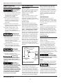
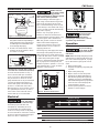
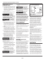
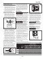
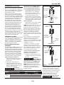
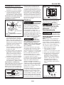
More usable water is provided than
with a conventional type tank. Pre-
charged tanks are specified in terms
of a conventional tank. For example,
a 20 gallon pre-charged tank will have
the same usable water or draw-down
capacity as a 40 gallon conventional
tank, but the tank is smaller in size
(Figure 1).
PRESSURE SWITCH
The pressure switch provides for
automatic operation. The pump starts
when pressure drops to a cut-in setting.
The pump stops when pressure reaches
a cut-out setting.
WELLS
A new well should be pumped clear of
sand before installing the pump. Sand
will damage the pumping parts and
seal. The draw-down level of the well
should not exceed the maximum rated
depth for the pump. The capacity of
the pump will be reduced and a loss of
prime may occur.
Installation
LOCATION
Select a location as close to the water
supply as possible.
Be sure to comply with any state or
local codes regarding the placement
of the pump. The equipment must
be protected from the elements. A
basement or heated pump house is a
good location. Make sure the pump has
proper ventilation. The temperature
surrounding the pump is not to exceed
100° F (38°C) or nuisance tripping of the
motor overload may occur.
This pump is
designed for indoor
installation only. Failure to install indoors
will significantly increase the risk of injury
or death from electrical shock.
PIPING
Piping may be copper, steel, rigid PVC
plastic or flexible polyethylene plastic.
Flexible pipe is NOT
recommended on
suction pipe (inlet pipe).
The pipe must be clean and free of rust
or scale. Use a pipe joint compound
on the male threads of the metal pipe.
Plumber's seal tape should be used with
plastic threads. All connections must be
air tight to insure normal operation.
All wiring SHOULD
be performed by a
licensed or certified electrician.
11. For maximum safety, the unit should
be connected to a grounded circuit
equipped with a ground fault
interrupter device (GFCI).
12. Before installing the pump, have
the electrical outlet checked by a
licensed or certified electrician to
make sure the outlet is properly
grounded.
13. Make sure the line voltage and
frequency of electrical current supply
agrees with the motor wiring.
14. Do NOT attempt repairs to the
electric motor. All repairs to the
motor must be completed at a
licensed or certified electrical motor
repair shop.
Do NOT touch an
operating motor.
Modern motors are designed to operate
at high temperatures.
15. Avoid kinking electrical cord and
protect electrical cord from sharp
objects, hot surfaces, oil and
chemicals. Replace damaged or worn
cords immediately.
16. Keep fingers and foreign objects
away from ventilation and other
openings. Do NOT insert any objects
into the motor.
Risk of electric
shock! NEVER
connect the green (or green and yellow
wire) to a live terminal!
17. Use wire of adequate size to
minimize voltage drop at the motor.
Do NOT handle
pump or pump
motor with wet hands, when standing
on a wet or damp surface or when
standing in water. Fatal electrical shock
WILL occur.
Pump motor is
equipped with an
automatic resetting thermal protector and
may restart unexpectedly. Protector tripping
is an indication of motor overheating
because of operating pump at low heads
(low discharge restriction), excessively high
or low voltage, inadequate wiring, incorrect
motor connections,excessive surrounding
air temperature, inadequate ventilation,
and/or defective motor or pump.
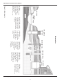
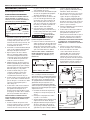
Pre-Installation
WATER SUPPLIES
The water supplies illustrated in Figure
16 (on page 8) are possible sources for
water. These water supplies can be
divided into two categories:
SURFACE WATER
Water from a lake, stream, pond and
cistern. This water is usually not fit
for human consumption, but may be
suitable for washing, irrigation or other
household uses.
GROUND WATER
Water found in the water bearing
stratum at various levels beneath the
earth. Of all the fresh water found on
earth only 3 percent is found on the
surface and 97 percent is underground.
TANKS - CONVENTIONAL STORAGE
The function of the tank is to store a
quantity of water under pressure. When
full, the tank contains approximately
2/3 water and 1/3 compressed air. The
compressed air forces the water out
of the tank when a faucet is opened.
An air volume control automatically
replaces air lost or absorbed into the
water. The usable water, or draw-down
capacity, of the tank is approximately
1/6 of the tanks total volume when
operated on a “20-40” pressure setting
(Figure 1).
TANKS - PRE-CHARGED STORAGE
A pre-charged storage tank has a
flexible bladder or diaphragm that acts
as a barrier between the compressed
air and water. This barrier prevents the
air from being absorbed into the water
and allows the water to be acted on by
compressed air at initially higher than
atmospheric pressures (pre-charged).
Figure 1 - Conventional and
Pre-charged Storage Tanks
AIR VOLUME
CONTROL
CONVENTIONAL
TANK
PRE-CHARGED
TANK
BLADDER

3
www.waynepumps.com
Installation (Continued)
Slope all inlet piping upwards towards
the pump to prevent trapping air.
Unions or hose couplings can be
installed near pump to facilitate removal
for servicing or storage. A rubber hose
installed between the water system and
the house piping will reduce the noise
transmitted to the house.
Plastic pipe can be used on all
installations except 2 in. deep well jet.
The 2 in. deep well jet requires 1-1/4
in. galvanized steel pipe and special
machined couplings (1-13/16 in. O. D.).
The galvanized steel pipe and the
couplings restrict the flow of return
water back to the jet unless the
couplings are machined.
PIPE SIZES
Long horizontal pipe runs and an
abundance of fittings and couplers
decrease water pressure due to
friction loss. See Chart 1, on page 4, to
determine the proper pipe size.
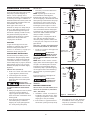
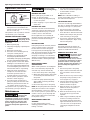
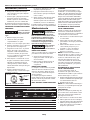
SHALLOW WELL INSTALLATION
A shallow well jet assembly can be
used with the deep well pump when
the pump is located 25 feet vertically
of the water level (See converting to
shallow well pump on page 5). Shallow
well installations have only one pipe
between the pump and water supply
(Figure 2).
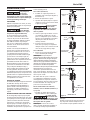
DRILLED WELL (FIGURE 16)
1. Install a foot valve on the first section
of pipe (Figure 2, Illustration A).
2. Lower the pipe into the well.
3. Add pipe until the foot valve is 5
feet below the lowest anticipated
water level.
The foot valve
should be at least 18
in. from the bottom of the well or sand
or sediment COULD be drawn into the
system.
4. After proper depth is reached, install
a well seal or pitless adapter to
support pipe and prevent surface.
water and other contaminants from
entering well.
5. Slope the horizontal pipe upward
toward the pump to eliminate
trapping air. Sloping the pipe will
also aid in priming the pump.
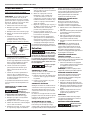
DRIVEN WELL
• Drive the point several feet below
the water table.
NOTE: A packer type foot valve can
be installed in the well (Figure 2,
Illustration B). This type of foot valve
allows the piping to be filled with water
when priming and makes the inlet pipe
much easier to test for leaks. Follow
the manufacturer’s instructions when
installing the packer type foot valve.
As an alternative, an in-line check valve
can be used with a driven well (Figure
2, Illustration C). The pipe between the
check valve and the water level will
always be under a vacuum.
Leaking joints or couplings will allow
air to leak into the pipe and cause
abnormal pump operation. Make sure
to use pipe joint compound on all male
pipe threads.
DUG WELL, CISTERN, LAKE AND SPRING
INSTALLATION (FIGURE 16, ON PAGE 8)
• Install a foot valve on inlet pipe and
lower into water.
The foot valve
SHOULD be at least
18 in. from the bottom of the well or
sand or sediment COULD be drawn into
the system.
NOTE: When a lake is used as a water
supply, make sure the inlet pipe is deep
enough to be submerged at all times.
Slope the horizontal piping upward
toward the pump to prevent trapping
air. The pipe must be removed during
winter months or protected against
freezing.
Protect the pipe from damage from
swimmers and boats.
Install a screen
around the inlet
pipe to prevent the entrapment of
swimmers.
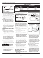
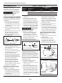
DEEP WELL INSTALLATION
DRILLED WELL (4 IN. OR LARGER) WITH
TWO PIPE JET (FIGURES 16, ON PAGE 8
AND 3, ON PAGE 4)
1. Assemble a 1-1/4 in. foot valve (not
included) to the jet body. A 1-1/4 in.
coupling is required to connect the
larger pipe to the jet assembly.
2. Connect the 1 in. pipe threads into
the smaller opening in the jet body.
3. Lower the jet into the well. Add pipe
as needed. Be sure to use pipe joint
compound, or plumber's seal tape
on all male threads.
CWS Series
TO PUMP
WELL
SEAL
FOOT
VALVE
WELL
CASING
TO
PUMP
DRIVE
POINT
INLINE
CHECK
VALVE
PACKER TYPE
FOOT VALVE
Illustration A
Illustration C
Illustration B
Figure 2
TO
PUMP
DRIVE
POINT

4
www.waynepumps.com
Installation (Continued)
4. Position the jet 10 - 20 feet below
the lowest anticipated water level,
but never closer than 5 feet from the
bottom of the well, if possible.
5. Install a well seal to support the pipe
and prevent surface water and other
contaminants from entering the
well.
6. Install the horizontal pipe from
the well to the pump. Piping from
the vertical well pipe to the pump
should never be smaller than the
well pipes.
7. Slope both pipes upward toward the
pump to prevent trapping air. If the
horizontal distance exceeds 25 feet,
see Chart 1 for the recommended
pipe sizes.
DUG WELL, CISTERN, LAKE AND SPRING
WITH TWO PIPE JET (FIGURE 16, ON
PAGE 8)
1. Install a 1-1/4 in. foot valve (not
included) to the jet body. A 1-1/4 in.
coupling is required to connect the
larger pipe to the jet assembly.
2. Connect the 1 in. pipe threads into
the smaller opening in the jet body.
3. Lower the jet into the water below
the lowest anticipated water level,
but never closer than 18 in. from
the bottom. Sand or debris may be
drawn into the system if the jet is
too close to the bottom.
4. Provide protection for the jet and
pipes against damage from boats
or swimmers if a lake is used for the
water supply.
Install a screen
around the inlet
pipe to prevent the entrapment of
swimmers.
5. Slope the horizontal pipes upward
toward the pump to prevent
trapping air. If horizontal distance
exceeds 25 feet, see Chart 1 for
recommended pipe sizes.
DRILLED WELL (2 IN.) WITH SINGLE PIPE
PACKER (FIGURES 16 AND 4)
NOTE: Single pipe packer jets rely on
the space between single pipe and
inside of well casing for return water to
operate jet. Two inch installations must
use 1-1/4 in. galvanized steel pipe with
special turned couplings (1-13/16 in.
O.D.) to avoid restricting flow of return
water back to jet.
1. Assemble the foot valve and packer
to the jet body.
2. Lubricate the rubber cups with
petroleum jelly.
3. Attach the first section of pipe and
lower jet into well.
4. Add pipe until the jet is positioned 5 -
15 feet below the lowest anticipated
water level. The jet should never be
closer than 5 feet from the bottom of
the well or sand and sediment may
be drawn into the system.
5. With the jet in position, fill the pipes
with water to make sure the rubber
cups are sealed against inside of the
well casing. It may be necessary to move
the jet up and down to seat the cups.
6. Install the casing adapter and the
horizontal pipes.
7. Slope both pipes upward toward
the pump to eliminate trapping
air. If the horizontal distance
exceeds 25 feet, see Chart 1 for the
recommended pipe sizes.
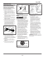
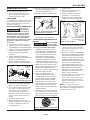
DEEP WELL PUMP WITH HORIZONTAL
AND VERTICAL STORAGE TANK
(FIGURES 5 AND 6)
1. Install the air volume control on the
tank as shown.
2. Connect the copper tube from the
air volume control to the 1/8 in. NPT
opening directly above the 1-1/4 in.
opening on the front of the pump.
3. Install a valve and isolating hose
between the system and the house
plumbing to aid in pump removal
for servicing and for reducing noise
transmitted through the house piping.
4. Provide a hose bib (faucet) at the
lowest point in the system to drain
for service or storage.
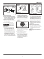
DEEP WELL PUMP WITH PRE-CHARGED
STORAGE TANK (FIGURE 7)
1. Check tank pre-charge using a tire
pressure gauge. Set air pressure in tank
to 28 psi which is 2 psi below pressure
switch cut-in level. An air valve is located
on the side and will accept a standard
fitting from a bicycle pump or air line.
2. Check the pressure with the power
off, faucets open and no water
flowing (zero water pressure).
Operating Instructions & Parts Manual
Figure 3 - Two Pipe Jet
JET BODY
FOOT VALVE
1-1/4 IN. PIPE
1 IN.
PIPE
Figure 4 - Single Pipe Jet
PACKER
FOOT VALVE
1-1/4 IN. PIPE
CUPS
CHART 1 - PIPE SIZING
Pump Model
Pump
Opening
Horizontal Distance
(Feet)
0-25 26-100
Deep Well Inlet: Suction 1-1/4 in. 1-1/2 in.
Inlet: Drive 1 in. 1-1/4 in.
Outlet 3/4 in. 1 in.
Figure 5 - Horizontal Tank
AIR
VOLUME
CONTROL
TUBING
SUCTION
OUTLET
AIR
VOLUME
CONTROL
DRIVE
PRESSURE
SWITCH
PRIME
PLUG
Figure 6 - Vertical Tank
OUTLET
AIR VOLUME
CONTROL
TUBING
DRIVE
PRIMING PLUG
SUCTION
AIR VOLUME CONTROL

5
www.waynepumps.com
Installation (Continued)
3. Install a valve and isolator hose between
the system and the house plumbing to
aid in pump removal for servicing and
for reducing noise transmitted to the
house through the piping.
4. Provide a hose bib (faucet) at the
lowest point in the system to drain
for service or storage.
CONVERTING THE DEEP WELL PUMP TO
SHALLOW WELL OPERATION (FIGURE 8)
For shallow wells (25 feet or less), a
bolt-on shallow well jet is available
as an accessory for deep well pumps.
The jet attaches to the front of the
pump with the two bolts provided and
converts the deep well pump into a
shallow well pump. The shallow well
jet has a 1 in. NPT inlet and a 1/8 in.
NPT opening for an air volume control.
For optimum performance, an inline
check valve on the inlet side of the
shallow well jet is recommended.
Electrical
Risk of electrical
shock. This pump is
designed for indoor installation only.
Select the proper size wire and
fuse (Chart 2). Time delay fuses are
recommended over standard fuses
for motor circuit protection. All pump
motors have built-in automatic overload
protection that will prevent damage to
the motor due to overheating.
Do NOT connect to
electric power supply
until unit is permanently grounded.
Connect ground wire to approved ground
then connect terminal provided.
A metal underground water pipe or
well casing at least 10 feet long makes
the best ground electrode. If plastic
pipe or insulated fittings are used, run
a wire directly to the metal well casing
or use a ground electrode furnished by
the power company.
There is only one proper ground
terminal on the unit. The terminal is
located under the pressure switch cover,
is painted green and is identified as
GRD. The ground connection must be
made at this terminal (Figure 9).
The ground conductor must not be
smaller than the circuit conductors
supplying the motor.
The voltage of power supply must match
the voltage of the pump. The unit has
dual voltage motors preset at the factory
to 115 volts. The motors can be converted
to 230 volts by turning the voltage
selector to the desired voltage (see Figure
10, on page 5). Disconnect power, use
needle nose pliers to pull the selector out
approximately 1/4 in., rotate, and then
reinsert in correct position.
Disconnect power
and release ALL
pressure from the system before
attempting to install, service, relocate
or perform any maintenance.
Operation
PRIMING THE SHALLOW WELL PUMP
To prevent damage
to the pump, do NOT
start motor until pump has been filled
with water.
NOTE: When the deep well pump is used
with the bolt-on shallow well jet, be sure
the control valve slot (Figure 11, on page
6) is in the vertical (open) position at all
times.
1. Remove prime plug.
2. Fill pump and piping completely full
of water.
3. Replace the prime plug.
4. Open a faucet to vent the system.
5. Start the motor. Water will pump in a
few minutes. If pump fails to prime in
5 minutes, stop motor and refill pump
with water. Priming time is proportional
to the amount of air in inlet pipe. Do
not allow pump to get hot.
6. Let the system operate for several
minutes to flush all pipes.
CWS Series
Figure 7 - Pre-charged Storage Tank
OUTLET
PRIME
PLUG
TO DRIVE
TO JET
28-30 PSI PRECHARGE
1/2, 1/3 & 1 HP
TO
SUCTION
PRESSURE
SWITCH
Figure 8 - Shallow Well Jet
TO AIR VOLUME
CONTROL
JET
CHART 2 - RECOMMENDED FUSE AND WIRING DATA - 60 HZ MOTORS
HP Volt
Dual
Element
Fuse
250V
Distance in Feet
From Meter to Motor
0 51 101 201
to to to to
50 100 200 300
Wire Size
1/2
115 15 14 12 10 8
230 10 14 14 14 14
3/4
115 15 14 12 8 6
230 10 14 14 14 12
1
115 20 14 12 8 6
230 10 14 14 14 12
L2
3
L1
1
Figure 9 - Electrical Connections
MOTOR
LINE
GROUND
SCREW
Figure 10 - Voltage Selector
230 V
115 V

6
www.waynepumps.com
Operation (Continued)
7. Close faucet and allow pump to
build pressure in tank. When the
pressure reaches the cut-out setting,
the motor will stop.
The system is now in operation and will
automatically cycle on demand.
PRIMING THE DEEP WELL PUMP
To prevent damage
to the pump, do not
start motor until pump has been fi lled
with water.
1. Remove prime plug.
2. Fill pump and piping completely full
of water.
3. Replace the prime plug.
4. Close the control valve (Figure 11)
and open a nearby faucet.
5. Start the motor. The pressure inside
the pump body will build almost
immediately as the pump, jet and piping
become completely filled with water.
6. Slowly open the control valve. Water
will begin to flow. Continue to open
the control valve until maximum flow
is achieved. Opening the valve too far
will cause the water to stop flowing.
7. Adjust the valve until there is a
steady flow of water. The valve
should be opened as much as
possible without losing pressure.
8. Let the system operate for several
minutes to flush all piping.
9. Close the faucets and allow the
pump to build pressure in the tank.
When the pressure reaches the cut-
out setting, the motor will stop.
The system is now in operation and will
automatically cycle upon demand.
Maintenance
Disconnect power
and release ALL
pressure from the system before
attempting to install, service, relocate
or perform any maintenance. Lock the
power disconnect in the open (off)
position. Tag the power disconnect
to prevent unexpected application of
power.
Protect the pump
from freezing during
winter conditions.
DRAINING THE PUMP
Drain openings are provided on all
models. To drain the pump:
1. Remove drain plug and prime plug
to vent the system.
2. Drain all piping to a point below the
freeze line.
DRAINING THE TANK
Conventional tanks can be drained by
opening an outlet at the lowest point
in the system. Remove plug or the air
volume control to vent the tank.
Pre-charged tanks force virtually all
the water from the tank when system
pressure is released. No draining is
necessary.
RESTARTING PUMP
If the pump has been serviced, drained
or has not been used for some time,
be sure there is water in the pump
housing (volute) and the piping to the
well. There must be water in the pump
housing (volute) at all times when
the pump is running to avoid internal
damage of seal members (See Priming
the Shallow Well or Priming the Deep
Well Sections).
WATERLOGGED TANKS:
CONVENTIONAL
When a tank system has an inadequate
ratio of air and water, the pump will
start and stop often and erratically.
1. Disconnect the power to the pump.
2. Open the lowest faucet in the system
to release all pressurized water in
the system.
3. Prime the pump (See Priming the
Shallow Well or Priming the Deep
Well Sections).
4. Reconnect the power to the pump.
NOTE: As the pump refills the tank with
water, the air volume control supplies
the tank with the correct air to water
ratio for the system to operate. If the air
volume control is good, the pump will
shut off at the desired cut-off and will
be adjusted correctly.
WATERLOGGED TANKS: PRE-
CHARGED
If a pre-charged tank becomes
waterlogged, the bladder is normally
leaking or broken.
1. Test the tank by depressing the air
valve. The air valve will expel water
if the bladder is broken.
2. Replace the tank.
NOTE: Once a bladder is leaking or
broken, the bladder cannot be repaired.
The tank must be replaced.
PRE-CHARGED TANK
Some air is lost through the bladder in
any tank. To prevent tank failure, check
the tank pre-charge on a yearly basis.
1. Disconnect power to the pump
2. Open a faucet nearest the tank and
allow all water to drain from the tank.
3. Measure the tank pre-charge at the
valve stem using a tire gauge.
4. If necessary, adjust the pre-charge
with an air pump 28 - 30 psi on 1/2,
3/4 and 1 HP pumps.
LUBRICATION
The bearing used in the pumps are
lifetime lubricated at the factory and
require no additional lubrication.
REMOVING OLD SHAFT SEAL
Disconnect power
and release ALL
pressure from the system before
attempting to install, service, relocate
or perform any maintenance. Lock the
power disconnect in the open (off)
position. Tag the power disconnect to
prevent unexpected application of
power.
1. Disconnect power to the pump
2. Open a faucet nearest the tank and
allow all water to drain from the
tank.
3. Remove the four cap screws holding
the pump housing (volute) to the
motor (Figure 12, on page 7).
4. Separate the pump housing (volute)
from the motor to expose the
diffuser and the seal plate.
5. Remove the two cap screws and
diffuser from the seal plate to
expose the impeller.
6. Remove the small end cap on the
end of the motor opposite the
impeller.
7. With a large screwdriver, keep the
shaft from rotating and remove
the impeller with hand (standard
right hand thread). Be sure to hold
onto the cast iron seal plate when
removing the impeller from the
shaft.
Operating Instructions & Parts Manual
Figure 11 - Control Valve
CONTROL VALVE SLOT
OPEN
1/4 IN.
TURN
CLOSED

7
www.waynepumps.com
Maintenance (Continued)
8. Remove the seal plate.
9. Pry the rotating shaft seal member
(including stainless collar and rubber
seal) from the impeller (Figure 13).
10. Push or pry the ceramic seat free
from the seal plate (Figure 13).
11. Remove loose particles from impeller
hub and seal plate.
INSTALLING NEW SHAFT SEAL
Before handling
shaft seal parts,
wipe hands clean. Dirt or grease can
damage the seal.
1. Wet the inside of the seal cavity
on seal plate and the rubber cup
enclosing the new ceramic seat
with cooking oil. Be careful not to
scratch the ceramic surface of the
seal seat and push seat enclosed in
rubber into seal cavity on seal plate.
Use a cardboard washer to protect
polished surface when pushing
against ceramic seat with any object.
Be sure to remove cardboard washer.
2. Carefully slip seal plate over shaft
so as not to disturb seal position in
seal plate. The seal plate must be
orientated during assembly so that
the two holes are on a horizontal
line across the motor shaft (Figure
14). This placement should be done
to ensure proper draining and
priming.
3. Place rotating shaft seal member in
position on impeller and press into
place. Take care not to press against
polished seal surface.
4. Position impeller on shaft and
tighten securely (Figure 15).
5. Secure diffuser to seal plate using
the two cap screws. Be sure the
arrow on the front of the diffuser
is pointing up and the screws are
orientated on a horizontal line as
described in Step 2.
6. Carefully position pump housing
(volute) gasket over the diffuser
onto the seal plate. In all convertible
applications the seal ring must also
be positioned on the diffuser. In all
shallow well applications care must
be taken that the o-ring is clean and
properly positioned on the venturi.
Cleaning and positioning makes a
good seal inside the diffuser when
assembled.
7. Assemble the pump housing
(volute) to the motor using the
four cap screws. Be sure the pump
housing (volute) gasket is positioned
correctly and tighten the screws
securely.
NOTE: Shaft must rotate freely and
motor end cap should be secured before
operation.
CWS Series
Figure 12 - Convertible Well Pump
CAP
SCREWS
MOTOR
SEAL
PLATE
IMPELLER
DIFFUSER
PUMP
HOUSING
(VOLUTE)
DRAIN PLUG
Figure 13 - Removing Shaft Seal and
Ceramic Seat
ROTATING
SHAFT SEAL
MEMBER
RUBBER
SEAT
RING
IMPELLER
SEAL
PLATE
CERAMIC SEAT
Figure 14 - Seal Plate Replacement
SCREW
HOLES
MOTOR
SHAFT
Figure 15 - Motor Shaft
SEAL
FACING
MUST
BE CLEAN FOR
PROPER SEAL
MOTOR
SEAL
PLATE
IMPELLER
SEAL
SEAT
SEAL PLATE

8
www.waynepumps.com
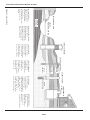
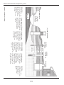
Operating Instructions & Parts Manual
(A) SPRING:
A spring that emerges
from the ground.
Occurs when water in
permeable materials is
trapped between
impermeable
material as rock or clay.
(B) LAKE, STREAM or POND:
Surface water, unless treated,
is usually not safe for human
consumption. It may be used
for purposes such as washing
or irrigation.
(C) DUG WELL:
A hole is excavated
several feet in diameter
to a fairly shallow
depth. It is then lined
with brick, stone or
concrete to prevent
cave-in.
(D) DRIVEN WELL:
Pipe with a pointed
screen is driven into
the ground below
the water table.
The depth is usually
less than 50 feet.
Available
diameters are
1" throu
g
h 2".
(E) DRILLED WELL:
A hole bored into the
earth with machinery and
lined with pipe. Depths
range from a few feet
to over 1000 feet.
Common well diameters
are 2", 3", 4" and 6" for
domestic water wells.
(F) CISTERN:
An underground tank
built to collect rain
water from rooftops.
The water is not fit
for human consumption.
(A) SPRING
(B) LAKE,
STREAM, POND
(C) DUG WELL
(D) DRIVEN WELL
(E) DRILLED WELL
(F) CISTERN
SHALE
TOP SOIL
CLAY
PERMEABLE
MATERIAL
WATER
BEARING
SAND
WATER TABLE
Water Supplies
Figure 16 - Water Supplies

9
www.waynepumps.com
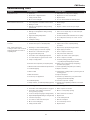
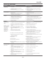
Symptom Possible Cause(s) Corrective Action
Pump will not run 1. Power off
2. Blown fuse or tripped breaker
3. Faulty pressure switch
4. Motor overload tripped
1. Turn power on or call power com pa ny
2. Replace fuse or reset circuit break er
3. Replace switch
4. Let cool. Overload will au to mat i cal ly re set
Motor hums but will not run 1. Line voltage does not match selector switch
2. Wiring too small
3. Damage or misalignment causing rotating
parts to bind
1. Check voltage
2. Rewire
3. Replace or take to service shop for re pair
Overload trips 1. Incorrect line voltage
2. Damage or misalignment causing rotating
parts to bind
3. High surrounding temperature
4. Rapid cycling
5. Inadequate wiring
1. Rewire
2. Take to motor repair shop or locate and repair
mechanical binding
3. Provide a shaded, well-ventilated area for pump
4. See "Pump starts and stops too often" sec tion
5. Rewire
Pump runs but delivers little or
no water
Note: Check prime before
looking for other causes. Unscrew
priming plug and see if water is
in priming hole.
1. Water level below pump intake
2. Control valve open too far (deep well)
3. Discharge not vented while priming
4. Leaking in piping on well side of pump
5. Well screen or inlet strainer clogged
6. Clogged nozzle (deep well)
7. Air volume control diaphragm ruptured
8. Foot valve may be clogged or stuck closed
9. Pump not fully primed
10. Control valve completely closed (deep well)
11. Water level below maximum lift spec i fi ca tion
12. Undersized piping
13. Gaseous well
14. Distorted venturi
15. Incorrect jet for application
16. Undersized pump
17. Pump cavitates, (sounds like pumping gravel)
1. Lower suction pipe further into well
2. Adjust control valve or repeat priming
procedure.
3. Open faucet, repeat priming pro ce dure
4. Repair piping as needed
5. Clean or replace as necessary
6. Pull jet and clear obstruction
7. Replace air volume control (See Page 6)
8. Clean or replace as needed
9. Continue priming, paus ing ev ery 5 min utes to
cool pump body. Refill pump as need ed
10. Adjust control valve per deep well prim ing
procedure (see page 6)
11. Select applicable pump and/or jet as sem bly
12. Replace as needed
13. Install baffle on pump intake to pre vent gas from
entering system
14. Inspect and replace
15. Purchase a jet matched to your sys tem when
replacing another brand pump
16. Increase horsepower of pump
17. Increase suction plumbing diameter or decrease
pipe friction
Pump starts and stops too of ten 1. Water logged tank (conventional tank)
2. Air volume control tubing kinked or clogged
3. Air volume control tubing connected to
wrong opening on pump
4. Incorrect tank pre-charge (pre-charged tank)
5. Ruptured diaphragm/bladder (pre-charged tank)
6. Leak in house piping
7. Foot valve or check valve stuck open
8. Motor overload tripping
9. Faulty pressure switch
1. See waterlogged conventional tank on page 6
2. Clean or replace as needed
3. Move to correct pump opening
4. Add or release air as needed
5. Replace tank
6. Locate and repair leak
7. Remove and replace
8. See overload trips section
9. Replace switch
Troubleshooting Chart
CWS Series

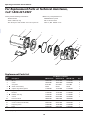
10
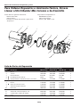
For Replacement Parts or Technical Assistance,
Call 1-800-237-0987
Please provide following information: Address any correspondence to:
- Model number WAYNE Water Systems
- Serial number (if any) 101 Production Drive
- Part description and number as shown in parts list Harrison, OH 45030 U.S.A.
www.waynepumps.com
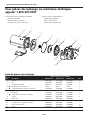
Replacement Parts List
Ref.
No.
Part Number for Models
Description CWS50-1/2 HP CWS75-3/4 HP CWS100-1 HP Qty.
1 Motor 32059-001 32142-002 32142-001 1
2 Screw 16636-002 16636-002 16636-002 4
3 Seal plate 4372-001 4372-001 4372-001 1
4
●
Shaft seal assembly 56393 56393 56393 1
5
●
Square ring rubber gasket 17150-001 17150-001 17150-001 1
6 Impeller 23285-002 23285-001 23285-001 1
7 Diffuser 17148-001 17148-001 17148-001 1
8
●
Rubber seal ring 17149-001 17149-001 17149-001 1
9 Volute 56870-001 56870-001 56870-001 1
10 Pressure switch 30010-001 30010-001 30010-001
11 O-ring 15592 15592 15592 1
12 Control valve (includes #11) 56883-001 56883-001 56883-001 1
13 Pipe plug 1/8 in. 15766-002 15766-002 15766-002 2
14 Base 23029-001 23029-001 23029-001 1
●
Repair kit (includes #4, 5 & 8) 56874-001 56874-001 56874-001 1
Operating Instructions & Parts Manual
1
2
3
4
5
6
7
8
9
10
11
12
13
14

11
www.waynepumps.com
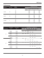
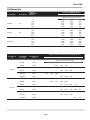
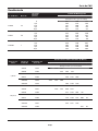
Performance
Model No. Motor HP
Suction
Lift (Feet)
Discharge Pressure PSI
30 40 50
Output in Gallons Per Hour (GPH)
CWS50 1/2
0
10
20
30
40
900
780
690
570
456
660
570
450
348
270
408
300
210
150
60
CWS75 3/4
0
10
20
30
40
990
906
774
630
510
780
630
510
408
306
462
330
270
216
156
CWS100 1
0
10
20
30
40
1056
948
846
750
642
840
750
642
528
384
588
444
330
264
234
CWS Series
Jet Diameter
Pump Model
No.
Jet Assembly
No.
Vertical Distance to Pumping Level
30' 40' 50' 60' 70' 80' 90' 100'
Output in Gallons Per Hour (GPH)
2 in.
CWS50
CWS50
56319
55462
620 590 500
400 335 260
CWS75
CWS75
56322
55462
840 740 615
390 360 290
CWS100
CWS100
56322
58319
890 780 650
520 420 330
4 in.
CWS50
CWS50
CWS50
56324
56317
55465
900 750
690 580 540
415
390
335 275 210
CWS75
CWS75
56324
55465
900 800 675
470 420 340 280 200
CWS100
CWS100
CWS100
56324
56317
55465
950 840 706
585 490 390
315 230

12
www.waynepumps.com
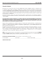
Limited Warranty
For three years from the date of purchase, WAYNE Water Systems (“WAYNE”) will repair or re place, at its option, for the
original purchaser any part or parts of its Sump Pumps or Water Pumps (“Product”) found upon examination by WAYNE to be
defective in materials or work man ship. Please call WAYNE (800-237-0987) for instructions or see your dealer. Be pre pared to
provide the model and serial number when exercising this warranty. All trans por ta tion charges on Products or parts submitted
for repair or replacement must be paid by purchaser.
This Limited Warranty does not cover Products which have been damaged as a result of accident, abuse, misuse, neglect,
improper installation, improper main te nance, or failure to operate in accordance with WAYNE’S written instructions.
THERE IS NO OTHER EXPRESS WARRANTY. IM PLIED WARRANTIES, IN CLUD ING THOSE OF MER CHANT ABIL I TY AND
FITNESS FOR A PARTICULAR PUR POSE, ARE LIMITED TO THREE YEARS FROM THE DATE OF PUR CHASE. THIS IS THE
EXCLUSIVE REM E DY AND ANY LIABILITY FOR ANY AND ALL IN DI RECT OR CON SE QUEN TIAL DAM AG ES OR EX PENS ES
WHATSOEVER IS EXCLUDED.
Some states do not allow limitations on how long an implied warranty lasts, or do not allow the exclusions or limitations of
incidental or consequential damages, so the above lim i ta tions might not apply to you. This limited war ran ty gives you specific
legal rights, and you may also have other legal rights which vary from state to state.
In no event, whether as a result of breach of contract warranty, tort (in clud ing negligence) or otherwise, shall WAYNE or its
suppliers be liable for any special, consequential, incidental or penal damages including, but not limited to loss of profit or
revenues, loss of use of the products or any associated equipment, damage to associated equip ment, cost of capital, cost of
substitute products, facilities, services or replacement power, downtime costs, or claims of buyer’s cus tom ers for such damages.
You MUST retain your purchase receipt along with this form. In the event you need to exercise a warranty claim, you MUST
send a copy of the purchase receipt along with the material or correspondence. Please call WAYNE (800-237-0987) for return
authorization and instructions.
DO NOT MAIL THIS FORM TO WAYNE. Use this form only to maintain your records.
MODEL NO. _____________________ SERIAL NO. ________________________ INSTALLATION DATE _____________________
ATTACH YOUR RECEIPT HERE
Operating Instructions & Parts Manual
CWS Series
Page is loading ...
Page is loading ...
Page is loading ...
Page is loading ...
Page is loading ...
Page is loading ...
Page is loading ...
Page is loading ...
Page is loading ...
Page is loading ...
Page is loading ...
Page is loading ...
Page is loading ...
Page is loading ...
Page is loading ...
Page is loading ...
Page is loading ...
Page is loading ...
Page is loading ...
Page is loading ...
Page is loading ...
Page is loading ...
Page is loading ...
Page is loading ...
-
 1
1
-
 2
2
-
 3
3
-
 4
4
-
 5
5
-
 6
6
-
 7
7
-
 8
8
-
 9
9
-
 10
10
-
 11
11
-
 12
12
-
 13
13
-
 14
14
-
 15
15
-
 16
16
-
 17
17
-
 18
18
-
 19
19
-
 20
20
-
 21
21
-
 22
22
-
 23
23
-
 24
24
-
 25
25
-
 26
26
-
 27
27
-
 28
28
-
 29
29
-
 30
30
-
 31
31
-
 32
32
-
 33
33
-
 34
34
-
 35
35
-
 36
36


Wayne CWS75 Operating instructions
- Category
- Water pumps
- Type
- Operating instructions
Ask a question and I''ll find the answer in the document
Finding information in a document is now easier with AI
in other languages
- français: Wayne CWS75 Mode d'emploi
- español: Wayne CWS75 Instrucciones de operación
Related papers
-
Wayne CWS100 User manual
-
-
-
-
-
-
-
-
-
Other documents
-
Little GIANT 558274 Installation guide
-
-
RIDGID RSWS75 Operating instructions
-
K2 Pumps WPS05001K User guide
-
Sears 390252158 User manual
-
Craftsman SEARS 390.251483 User manual
-
-
Pentair Berkeley 10MS Owner's manual
-
STA-RITE MS Series Owner's manual
-