Black & Decker C7501M User manual
- Category
- Air compressors
- Type
- User manual
This manual is also suitable for
Part No. N020206-NOV08-0
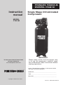
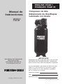
Single Stage Oil lubricated
Compressor
Instruction
manual
To learn more about Porter-Cable
visit our website at:
www.deltaportercable.com
The Model and Serial No. plate is located on the
frame. Record these numbers in the spaces below
and retain for future reference.
Model No._____________________________________
Type __________________________________________
Serial No.______________________________________
FRANÇAIS: PÁGINA 25
ESPAÑOL: PAGE 52
MODEL
C7501M
IMPORTANT
Please make certain that the person who
is to use this equipment carefully reads
and understands these instructions before
starting operations.
®
Copyright © 2008 Porter-Cable
2 - ENGN020206
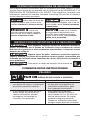
SAFETY GUIDELINES - DEFINITIONS
This manual contains information that is important for you to know and under-
stand. This information relates to protecting YOUR SAFETY and PREVENTING
EQUIPMENT PROBLEMS. To help you recognize this information, we use the
symbols below. Please read the manual and pay attention to these symbols.
Indicates an imminently
hazardous situation which, if not
avoided, will result in death or serious
injury.
Indicates a potentially
hazardous situation which, if not
avoided, may result in minor or
moderate injury.
Indicates a potentially
hazardous situation which, if not
avoided, could result in death or
serious injury.
Used without the
safety alert symbol indicates a
potentially hazardous situation which,
if not avoided, may result in property
damage.
IMPORTANT SAFETY INSTRUCTIONS
This product contains chemicals known to the State of
California to cause cancer, and birth defects or other reproductive harm.
Wash hands after handling.
Some dust contains chemicals known to the State of
California to cause cancer, birth defects or other reproductive harm such as
asbestos and lead in lead based paint.
To reduce the risk of injury, read the instruction manual.
SAVE THESE INSTRUCTIONS
HAZARD
RISK OF EXPLOSION OR FIRE
WHAT CAN HAPPEN HOW TO PREVENT IT
• Itisnormalforelectricalcon-
tacts within the motor and
pressure switch to spark.
• Alwaysoperatethecompres-
sor in a well ventilated area
free of combustible materials,
gasoline, or solvent vapors.
• Ifelectricalsparksfromcompres-
sor come into contact with flam-
mable vapors, they may ignite,
causing fire or explosion.
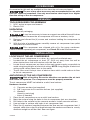
• Ifsprayingflammablemateri-
als, locate compressor at least
20' (6.1 m) away from spray
area. An additional length of
air hose may be required.
• Storeflammablemateri-
als in a secure location
away from compressor.
3 - ENG N020206
• Restrictinganyofthecom-
pressor ventilation openings
will cause serious overheat-
ing and could cause fire.
• Neverplaceobjectsagainst
or on top of compressor.
• Operatecompressorinanopen
area at least 12" (30.5 cm) away
from any wall or obstruction that
would restrict the flow of fresh
air to the ventilation openings.
• Operatecompressorinaclean,
dry well ventilated area. Do
not operate unit in any con-
fined area. Store indoors.
• Unattendedoperationofthisprod-
uct could result in personal injury
or property damage. To reduce the
risk of fire, do not allow the com-
pressor to operate unattended.
• Alwaysremaininattendancewith
the product when it is operating.
• Alwaysturnoffanddisconnect
electrical supply from unit
when not in use.
HAZARD
RISK TO BREATHING (ASPHYXIATION)
WHAT CAN HAPPEN HOW TO PREVENT IT
• Thecompressedairdirectlyfrom
your compressor is not safe for
breathing. The air stream may con-
tain carbon monoxide, toxic vapors,
or solid particles from the air tank.
Breathing these contaminants can
cause serious injury or death.
• Neveruseairobtaineddirectly
from the compressor to supply
air for human consumption. The
compressor is not equipped with
suitable filters and in-line safety
equipment for human consumption.
• Exposuretochemicalsindustcre-
ated by power sanding, sawing,
grinding, drilling, and other con-
struction activities may be harmful.
• Sprayedmaterialssuchaspaint,
paint solvents, paint remover, insec-
ticides, weed killers, may contain
harmful vapors and poisons.
• Workinanareawithgoodcross
ventilation. Read and follow the
safety instructions provided on
the label or safety data sheets
for the materials you are spray-
ing. Always use certified safety
equipment: NIOSH/OSHA respi-
ratory protection or properly fit-
ting face mask designed for use
with your specific application.
HAZARD
RISK OF SERIOUS INJURY OR PROPERTY DAMAGE
WHEN TRANSPORTING COMPRESSOR
WHAT CAN HAPPEN HOW TO PREVENT IT
• Oilcanleakorspillandcouldresult
in fire or breathing hazard; serious
injury or death can result. Oil leaks
will damage carpet, paint or other
surfaces in vehicles or trailers.
• Alwaysplacecompressorona
protective mat when transport-
ing to protect against damage to
vehicle from leaks. Remove com-
pressor from vehicle immediately
upon arrival at your destination.
• Always transport and store
unit in an upright position.

4 - ENGN020206
HAZARD
RISK OF BURSTING
Air Tank: The air tank on your compressor is designed and may be UM coded [for
units with air tanks greater than 6" (152.4 mm) diameter] according to ASME Section
VIII, Div. 1 rules. All pressure vessels should be inspected once every two years.
To find your state pressure vessels inspector, look under the Division of Labor and
Industries in the government section of a phone book .
The following conditions could lead to a weakening of the air tank, and result in a
violent air tank explosion:
WHAT CAN HAPPEN HOW TO PREVENT IT
• Failuretoproperlydraincondensed
water from air tank, causing rust
and thinning of the steel air tank.
• Drainairtankdailyoraftereachuse.
If air tank develops a leak, replace
it immediately with a new air tank
or replace the entire compressor.
• Modificationsorattempted
repairs to the air tank.
• Neverdrillinto,weld,ormakeany
modifications to the air tank or its
attachments. Never attempt to
repair a damaged or leaking air
tank. Replace with a new air tank.
• Unauthorizedmodifica-
tions to the safety valve or
any other components which
control air tank pressure.
• Theairtankisdesignedtowith-
stand specific operating pres-
sures. Never make adjustments
or parts substitutions to alter the
factory set operating pressures.
• Excessivevibrationcanweakenthe
air tank of a stationary compressor
and cause an explosion.
• The compressor must be properly
mounted, see Anchoring under
Installation.
Attachments & accessories:
• Exceedingthepressureratingof
air tools, spray guns, air oper-
ated accessories, tires, and other
inflatables can cause them to
explode or fly apart, and could
result in serious injury.
• Follow the equipment manufac-
turers recommendation and never
exceed the maximum allowable
pressure rating of attachments.
Never use compressor to inflate
small low pressure objects such
as children’s toys, footballs, bas-
ketballs, etc.
Tires:
• Overinflationoftirescouldresultin
serious injury and property damage.
• Useatirepressuregaugetocheck
the tires pressure before each use
and while inflating tires; see the tire
sidewall for the correct tire pressure.
NOTE: Air tanks, compressors and simi-
lar equipment used to inflate tires can fill
small tires similar to these very rapidly.
Adjust pressure regulator on air supply
to no more than the rating of the tire
pressure. Add air in small increments
and frequently use the tire gauge to pre-
vent over inflation.

5 - ENG N020206
HAZARD
RISK OF ELECTRICAL SHOCK
WHAT CAN HAPPEN HOW TO PREVENT IT
• Yourcompressorispoweredby
electricity. Like any other electrically
powered device, if it is not used
properly it may cause electric shock.
• Neveroperatethecompres-
sor outdoors when it is rain-
ing or in wet conditions.
• Neveroperatecompressorwithpro-
tective covers removed or damaged.
• Repairsattemptedbyunqualified
personnel can result in serious
injury or death by electrocution.
• Anyelectricalwiringorrepairs
required on this product should be
performed by authorized service
center personnel in accordance with
national and local electrical codes.
• Electrical Grounding: Failure to
provide adequate grounding to this
product could result in serious injury
or death from electrocution. Refer
to Grounding Instructions para-
graph in the Installation section.
• Makecertainthattheelectrical
circuit to which the compressor is
connected provides proper elec-
trical grounding, correct voltage
and adequate fuse protection.
HAZARD
RISK FROM FLYING OBJECTS
WHAT CAN HAPPEN HOW TO PREVENT IT
• Thecompressedairstreamcan
cause soft tissue damage to
exposed skin and can propel dirt,
chips, loose particles, and small
objects at high speed, resulting in
property damage or personal injury.
• Alwayswearcertifiedsafetyequip-
ment: ANSI Z87.1 eye protection
(CAN/CSA Z94.3) with side shields
when using the compressor.
• Neverpointanynozzleorsprayer
toward any part of the body or
at other people or animals.
• Alwaysturnthecompres-
sor off and bleed pressure from
the air hose and air tank before
attempting maintenance, attach-
ing tools or accessories.
HAZARD
RISK OF HOT SURFACES
WHAT CAN HAPPEN HOW TO PREVENT IT
• Touchingexposedmetalsuch
as the compressor head, engine
head, engine exhaust or outlet
tubes, can result in serious burns.
• Nevertouchanyexposedmetal
parts on compressor during or
immediately after operation.
Compressor will remain hot for
several minutes after operation.
• Donotreacharoundprotective
shrouds or attempt maintenance
until unit has been allowed to cool.

6 - ENGN020206
HAZARD
RISK FROM MOVING PARTS
WHAT CAN HAPPEN HOW TO PREVENT IT
• Movingpartssuchasthepulley,
flywheel, and belt can cause seri-
ous injury if they come into con-
tact with you or your clothing.
• Neveroperatethecompres-
sor with guards or covers which
are damaged or removed.
• Keepyourhair,clothing,and
gloves away from moving parts.
Loose clothes, jewelry, or long hair
can be caught in moving parts.
• Airventsmaycovermovingparts
and should be avoided as well.
• Attemptingtooperatecompressor
with damaged or missing parts or
attempting to repair compressor
with protective shrouds removed
can expose you to moving parts
and can result in serious injury.
• Anyrepairsrequiredonthisproduct
should be performed by autho-
rized service center personnel.
HAZARD
RISK OF UNSAFE OPERATION
WHAT CAN HAPPEN HOW TO PREVENT IT
• Unsafeoperationofyour
compressor could lead to se ri ous
in ju ry or death to you or others.
• Reviewandunderstandallinstruc-
tions and warnings in this manual.
• Becomefamiliarwiththeoperation
and con trols of the air compressor.
• Keepoperatingareaclearofall
persons, pets, and obstacles.
• Keepchildrenawayfromthe
air compressor at all times.
• Donotoperatetheproduct
when fatigued or under the
influence of alcohol or drugs.
Stay alert at all times.
• Neverdefeatthesafetyfea
tures of this prod uct.
• Equipareaofoperation
with a fire extinguisher.
• Donotoperatemachinewithmiss-
ing, broken, or un au tho rized parts.
HAZARD
RISK OF INJURY FROM LIFTING
WHAT CAN HAPPEN HOW TO PREVENT IT
• Seriousinjurycanresult
from attempting to lift
too heavy an object.
• Thecompressoristooheavytobe
lifted by one person. Obtain assis-
tance from others before lifting.

7 - ENG N020206
HAZARD
RISK FROM NOISE
WHAT CAN HAPPEN HOW TO PREVENT IT
• Undersomeconditionsanddura-
tion of use, noise from this product
may contribute to hearing loss.
• Alwayswearcertifiedsafe-
ty equipment: ANSI S12.6
(S3.19) hearing protection.
SAVE THESE INSTRUCTIONS
FOR FUTURE USE
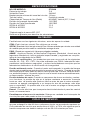
SPECIFICATIONS
Model No. C7501M
Running Horsepower *3.0
Voltage/Hertz/Phase 240V/60/1
Minimum Branch Circuit Requirement 15 Amp
Fuse Type Time Delay
Air Tank Capacity (Gallon) 60 ASME, Vertical (227.1 liters)
Approximate Cut-in Pressure 110 PSIG
Approximate Cut-out Pressure 135 PSIG
SCFM @ 40 PSIG *12.2
SCFM @ 90 PSIG *10.1
*Tested per ISO 1217
Refer to Glossary for abbreviations.
GLOSSARY
Become familiar with these terms before operating the unit.
CFM: Cubic feet per minute.
SCFM: Standard cubic feet per minute; a unit of measure of air delivery.
PSIG: Pounds per square inch gauge; a unit of measure of pressure.
Code Certification: Products that bear one or more of the following marks: UL,
CUL, ETL, CETL, have been evaluated by OSHA certified independent safety labo-
ratories and meet the applicable Standards for Safety.
Cut-In Pressure:Whilethemotorisoff,airtankpressuredropsasyoucontinue
touseyouraccessory.Whenthetankpressuredropstoacertainlowlevelthe
motor will restart automatically. The low pressure at which the motor automatically
restarts is called "cut-in" pressure.
Cut-Out Pressure:Whenanaircompressoristurnedonandbeginstorun,air
pressure in the air tank begins to build. It builds to a certain high pressure before
the motor automatically shuts off - protecting your air tank from pressure higher
than its capacity. The high pressure at which the motor shuts off is called "cut-
out" pressure.
Branch Circuit: Circuit carrying electricity from electrical panel to outlet.
To Lock Out Power: Place a lock on the line power switch so no one else can
turn on the power.
DUTY CYCLE
This air compressor pump is capable of running continuously. However, to prolong
the life of your air compressor, it is recommended that a 50%-75% average duty
cycle be maintained; that is, the air compressor pump should not run more than
30-45 minutes in any given hour.

8 - ENGN020206
ACCESSORIES
Accessories for this unit are available at the store the unit was purchased.
The use of any other accessory not recommended for use with
this tool could be hazardous. Use only accessories rated equal to or higher
than the rating of the air compressor.
ASSEMBLY
TOOLS REQUIRED FOR ASSEMBLY
1 - 9/16" socket or open end wrench
1 - Electric Drill
UNPACKING
1. Remove all packaging.
It may be necessary to brace or support one side of the outfit when
removing the pallet because the air compressor will have a tendency to tip.
2. Remove and discard the (4) screws and washers holding the compressor to
the pallet.
3. Withthehelpofanotherpersoncarefullyremoveaircompressorfrompallet
and place on a level surface.
This compressor was shipped with oil in the pump crankcase.
Check oil before operating air compressor, see Check Oil under Maintenance.
INSTALLATION
LOCATION OF THE AIR COMPRESSOR
• Locatetheaircompressorinaclean,dry,andwellventilatedarea.
• Located the air compressor at least 12" (30.5cm) away from the wall or
other obstructions that will interfere with the flow of air.
• Locatetheaircompressorasclosetothemainpowersupplyaspossibleto
avoid using long lengths of electrical wiring. NOTE: Long lengths of electrical
wiring could cause power loss to the motor.
• Theairfiltermustbekeptclearofobstructionswhichcouldreduceairflow
to the air compressor.
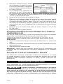
ANCHORING OF THE AIR COMPRESSOR
Risk of bursting. Excessive vibration can weaken the air tank
and cause an explosion. The compressor must be properly mounted.
The air compressor MUST be bolted to a solid, level surface.
Hardware needed:
4 - Concrete anchors (not supplied)
4 - 3/8" Lag screw to fit concrete anchors (not supplied)
4 Washers
(found in parts bag)
- shims (if needed)
1. Place the air compressor on on a solid, level surface.
2. Mark the surface using the holes in the air compressor feet as a template.
3. Drill holes in the surface for the concrete anchors. Install concrete anchors.
4. Line-up holes in surface with holes in air compressor feet.
5. Place the (4) washers (supplied) between the floor and air compressor feet. If
needed, solid shims may be placed between the washers and floor to evenly
distribute weight on all four feet. See next figure.

9 - ENG N020206
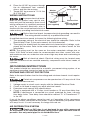
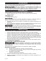
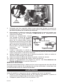
6. Place the (4) 3/8" lag screws through
the air compressor feet, washers,
shims, and into the anchors.
7. Torque 3/8" lag screws to 7-10 ft.-lbs
(9.5-13.5 Nm).
WIRING INSTRUCTIONS
Improper electrical instal-
lation of this product may void its war-
ranty and your fire insurance. Have circuit
wiring performed by qualified personnel
such as a licensed electrician who is
familiar with the current national electrical
code and any prevailing local electrical codes.
Risk of electrical shock. Improper electrical grounding can result in
electrical shock. The wiring should be done by a qualified electrician
A qualified electrician needs to knows the following before wiring:
1. The amperage rating of the electrical box should be adequate. Refer to the
Specification Chart, in the parts manual, for this information.
2. The supply line should have the same electrical characteristics (voltage, cycle,
phase) as the motor. Refer to the motor nameplate, on side of motor, for this
information.
NOTE: The wiring must be the same as the motor nameplate voltage plus or
minus 10%. Refer to local codes for recommended wire sizes, correct wire size,
and maximum wire run; undersize wire causes high amp draw and overheating to
the motor.
Risk of electrical shock. Electrical wiring must be located away
from hot surfaces such as manifold assembly, compressor outlet tubes, heads, or
cylinders.
GROUNDING INSTRUCTIONS
This product should be connected to a metallic, permanent wiring system, of an
equipment-grounding terminal or lead on the product.
VOLTAGE AND CIRCUIT PROTECTION
Refer to the specification chart for the voltage and minimum branch circuit require-
ments.
Certain air compressors can be operated on a 15 amp circuit if the
following conditions are met.
1. Voltage supply to circuit must comply with the National Electrical Code.
2. Circuit is not used to supply any other electrical needs.
3. Extension cords comply with specifications.
4. Circuit is equipped with a 15 amp circuit breaker or 15 amp time delay fuse.
NOTE: If compressor is connected to a circuit protected by fuses, use only
time delay fuses. Time delay fuses should be marked "D" in Canada and "T"
in the US.
If any of the above conditions cannot be met, or if operation of the compressor
repeatedly causes interruption of the power, it may be necessary to operate it from
a 20 amp circuit. It is not necessary to change the cord set.
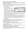
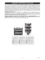
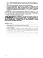
AIR DISTRIBUTION SYSTEM
Plastic or PVC pipe is not designed for use with compressed
air. Regardless of its indicated pressure rating, plastic pipe can burst from air
pressure. Use only metal pipe for air distribution lines.
3/8" Lag
Screw
(not supplied)
Washer
(supplied)
Shim Under
Washer
(not supplied)
Concrete Anchor
(not supplied)
Surface Line

10 - ENGN020206
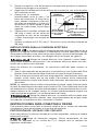
DRAIN
TRAP
DRAIN
TRAPS
DRAIN
LEGS
MOISTURE
SEPARATOR
AND TRAP
DIRT
LEG
DIRT
LEG
LUBRICATOR
REGULATOR
FILTER
AIR DISCHARGE
VALVE/ GLOBE VALV E
LUBRICATOR
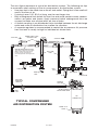
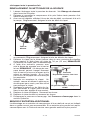
MAIN DISTRIBUTION AIR LINES
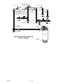
Slope pipe in direction of air flow.
Water condensate flows along
bottom of pipe to drain legs,
preventing it from entering feeder
lines.
REGULATOR
FLEXIBLE
COUPLING
DRAIN COCK
VALV E
TYPICAL COMPRESSED
AIR DISTRIBUTION SYSTEM
AIR FLOW
AIR FLOW
FEEDER LINES SLOPE
WITH AIR FLOW
AIR USAGE
LINES
AIR
COMPRESSOR
The next figure represents a typical air distribution system. The following are tips
to remember when setting up the air compressor’s air distribution system.
• Usepipethatisthesamesizeastheairtankoutlet.Pipingthatistoosmallwill
restrict the flow of air.
• Ifpipingisover100'(30.5m)long,usethenextlargersize.
• Buryundergroundlinesbelowthefrostlineandavoidpocketswhereconden-
sation can gather and freeze. Apply pressure before underground lines are
covered to make sure all pipe joints are free of leaks.
• Aflexiblecouplingisrecommendedtobeinstalledbetweentheairdischarge
outlet and main air distribution line to allow for vibration.
• Aseparateregulatorisrecommendedtocontroltheairpressure.Airpressure
from the tank is usually to high for individual air driven tools.
11 - ENG N020206
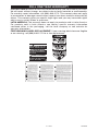
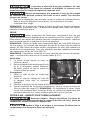
KNOW YOUR AIR COMPRESSOR
READ THIS OWNER’S MANUAL AND SAFETY RULES BEFORE OPERATING
YOUR UNIT. Compare the illustrations with your unit to familiarize yourself with
the location of various controls and adjustments. Save this manual for future
reference.
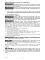
OPERATION
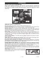
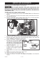
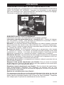
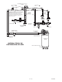
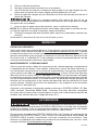
DESCRIPTION OF OPERATION
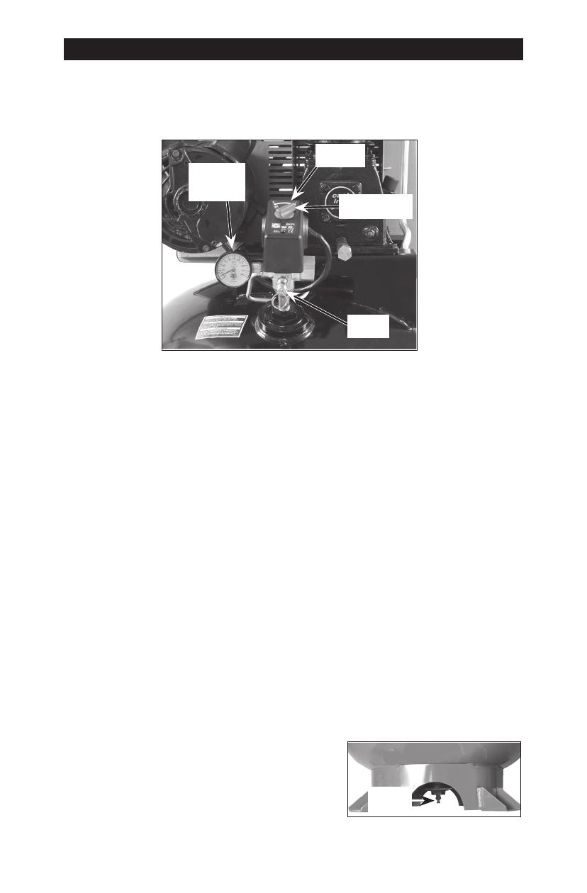
Become familiar with these controls before operating the unit.
Auto(I)/Off(0) Switch: Turn this switch "Auto (I)" to provide automatic power to the
pressure switch and "Off (O)" to remove power at the end of each use.
Pressure Switch: The pressure switch automatically starts the motor when the
air tank pressure drops below the factory set "cut-in" pressure. It stops the motor
when the air tank pressure reaches the factory set "cut-out" pressure.
Safety Valve: If the pressure switch does not shut off the air compressor at its
"cut-out" pressure setting, the safety valve will protect against high pressure by
"popping out" at its factory set pressure (slightly higher than the pressure switch
"cut-out" setting).
Tank Pressure Gauge: The tank pressure gauge indicates the reserve air pres-
sure in the tank.
Globe Valve: (sold separately, not shown) Opens and closes air discharge valve.
Turn knob counter-clockwise to open and clockwise to close.
Regulator (sold separately, not shown): An air pressure regulator or a separate
air transformer which combines the functions of air regulation and/or moisture and
dirt removal is recommended for most applications.
Cooling System (not shown): This compressor contains an advanced design
cooling system. At the heart of this cooling system is an engineered fan. It is per-
fectly normal for this fan to blow air through the vent holes in large amounts. You
know that the cooling system is working when air is being expelled.
Air Compressor Pump (not shown):Compressesairintotheairtank.Working
air is not available until the compressor has raised the air tank pressure above that
required at the air outlet.
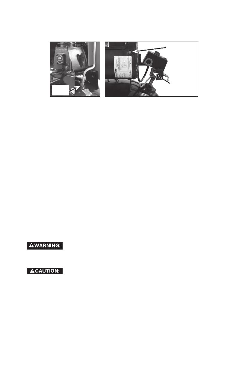
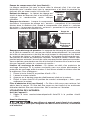
Drain Valve:The drain valve is located at the base
Drain
Valve
of the air tank and is used to drain condensation
at the end of each use.
Auto(I)/Off(O)
Switch
Safety
Valve
Tank
Pressure
Gauge
Pressure
Switch
12 - ENGN020206
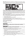
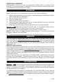
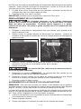
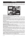
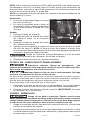
Check Valve:Whentheaircompressorisoperating,thecheckvalveis"open",
allowingcompressedairtoentertheairtank.Whentheaircompressorreaches
"cut-out" pressure, the check valve "closes", allowing air pressure to remain inside
the air tank.
Pressure
Release
Valve
Reset
Button
Check
Valve
Pressure Release Valve: The pressure release valve located on the side of the
pressure switch, is designed to automatically release compressed air from the
compressor head and the outlet tube when the air compressor reaches "cut-out"
pressure or is shut off. The pressure release valve allows the motor to restart freely.
Whenthemotorstopsrunning,airwillbeheardescapingfromthisvalveforafew
seconds. No air should be heard leaking when the motor is running or after the
unit reaches "cut-out" pressure.
Motor Overload Protector: This motor has a manual thermal overload protec-
tor. If the motor overheats for any reason, the overload protector will shut off the
motor. The motor must be allowed to cool down before restarting. To restart:
1. Place the Auto/Off lever in the "Off" position.
2. Allow the motor to cool.
3. Depress the red reset button on the motor.
4. Place the Auto/Off lever in the "Auto" postion to restart the motor.
Air Intake Filter (not shown): This filter is designed to clean air coming into
the pump. This filter must always be clean and ventilation openings free from
obstructions. See "Maintenance".
HOW TO USE YOUR UNIT
How to Stop:
1. Set the Auto/Off lever to "Off".
Before Starting
Do not operate this unit until you read and understand this
instruction manual for safety, operation and maintenance instructions.
Break-in Procedure
Risk of Unsafe Operation. Serious damage may result if the
following break-in instructions are not closely followed.
This procedure is required before the air compressor is put into service and when
the check valve or a complete compressor pump has been replaced.
1. Make sure the Auto/Off lever is in the "Off" position.
2. Check oil level in pump. See Oil paragraph in the Maintenance section for
instructions.
3. Recheck all wiring. Make sure wires are secure at all terminals connections.
Make sure all contacts move freely and are not obstructed.
4. Open the globe valve fully to permit air to escape and prevent air pressure
build up in the air tank during the break-in period.
5. Move the Auto/Off lever to "Auto" position. The compressor will start.
6. Run the compressor for 20 minutes. Make sure the globe valve is open and
there is minimal air pressure build-up in tank.

13 - ENG N020206
7. Check all air line fittings and connections/piping for air leaks by applying a
soap solution. Correct if necessary. NOTE: Minor leaks can cause the air
compressor to overwork, resulting in premature breakdown or inadequate
performance.
8. Check for excessive vibration. Readjust or shim air compressor feet, if neces-
sary.
9. After 20 minutes, close the globe valve. The air receiver will fill to "cut-out"
pressure and the motor will stop.
The compressor is now ready for use.
Before Each Start-Up
1. Place Auto/Off lever to "Off".
2. Close the globe valve.
3. Visually inspect air hose, replace if needed.
4. Attach hose and accessories.
Risk of unsafe operation. Firmly grasp air hose in hand when
installing or disconnecting to prevent hose whip.
Risk of unsafe operation. Do not use damaged or worn acces-
sories.
NOTE: A regulator MUST be installed when using accessories rated at less than
110 psi.
NOTE: The hose or accessory will require a quick connect plug if the air outlet is
equipped with a quick connect socket.
Risk of bursting. Too much air pressure causes a hazardous
risk of bursting. Check the manufacturer’s maximum pressure rating for air
tools and accessories. The regulator outlet pressure must never exceed the
maximum pressure rating.
Risk of unsafe operation. Compressed air from the unit may
contain wa ter condensation and oil mist. Do not spray un fil tered air at an item
that could be damaged by moisture. Some air tools and accessories may
require filtered air. Read the in struc tions for the air tools and accessories.
How to Start
1. Turn the Auto/Off lever to "Auto" and allow tank pressure to build. Motor will
stop when tank pressure reaches "cut-out" pressure.
2. Whenthetankpressurereaches"cutout"pressureopentheglobevalve.
IMPORTANT:Whenusingregulatorandotheraccessoriesrefertothemanufactur-
ers instructions.
Risk of bursting. If any unusual noise or vibration is noticed,
stop the compressor immediately and have it checked by a trained service
technician.
The compressor is ready for use.

14 - ENGN020206
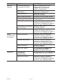
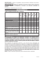
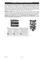
MAINTENANCE
CUSTOMER RESPONSIBILITIES
Before
each
use
Daily
or
after
each
use
Every
8
hours
Every
40
hours
Every
100
hours
Every
160
hours
Yearly
Check Safety Valve
•
Drain Tank
•
Oil Leaks
•
Check Pump Oil
•
Change Pump Oil
•
Unusual Noise and/or
Vibration
•
Air Filter • (1)
Drive Belt-Condition
•
Motor Pulley/Flywheel
alignment
•
Air compressor pump
intake and exhaust
valves
•
Inspect air lines and
fittings for leaks
•
Head Bolts - Check the torques of the head bolts after the first five hours of operation.
1- more frequent in dusty or humid conditions
Risk of unsafe operation. Unit cycles automatically when
power is on. When performing maintenance, you may be exposed to voltage
sources, compressed air, or moving parts. Personal injuries can occur. Before
performing any maintenance or repair, disconnect power source from the
compressor and bleed off all air pressure.
To ensure efficient operation and longer life of the air compressor outfit, a routine
maintenance schedule should be prepared and followed. The following routine
maintenance schedule is geared to an outfit in a normal working environment
operating on a daily basis. If necessary, the schedule should be modified to suit the
conditions under which your compressor is used. The modifications will depend
upon the hours of operation and the working environment. Compressor outfits in
an extremely dirty and/or hostile environment will require a greater frequency of all
maintenance checks.
NOTE: See Operation section for the location of controls.
TO CHECK SAFETY VALVE
Risk of bursting. If the safety valve does not work properly,
over-pressurization may occur, causing air tank rupture or an explosion.
Risk from flying objects. Always wear certified safety equip-
ment: ANSI Z87.1 eye protection (CAN/CSA Z94.3) with side shields.
1. Before starting compressor, pull the ring on the safety valve to make sure
that the safety valve operates freely. If the valve is stuck or does not operate
smoothly, it must be replaced with the same type of valve.

15 - ENG N020206
TO DRAIN TANK
Risk of unsafe operation. Air tanks contain high pressure air.
Keep face and other body parts away from outlet of drain. Use eye protection
[ANSI Z87.1 (CAN/CSA Z94.3)] when draining as debris can be kicked up into
face.
Risk from noise. Use ear protection (ANSI S12.6 (S3.19) as air
flow noise is loud when draining.
NOTE: All compressed air systems generate condensate that accumulates in any
drain point (e.g., tanks, filter, aftercoolers, dryers). This condensate contains lubricat-
ing oil and/or substances which may be regulated and must be disposed of in accor-
dance with local, state, and federal laws and regulations.
1. Set the Auto/Off lever to "Off".
2. Close the globe valve.
3. Remove the air tool or accessory.
4. Open the globe valve and allow the air to slowly bleed from the air tank until
tank pressure is approximately 20 psi.
5. Close the globe valve.
6. Drain water from air tank by opening drain valve on bottom of tank.
Risk of bursting. Water will condense in the air tank. If not
drained, water will corrode and weaken the air tank causing a risk of air tank
rupture.
Risk of property damage. Drain water from air tank may con-
tain oil and rust which can cause stains.
7. After the water has been drained, close the drain valve. The air compressor
can now be stored.
NOTE: If drain valve is plugged, release all air pressure. The valve can then be
removed, cleaned, then reinstalled.
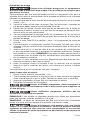
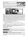
OIL
Use air compressor oil only. Multi-weight automotive engine
oils like 10W30 should not be use in air compressors. They leave carbon
deposits on critical components, thus reducing performance and compres-
sor life.
NOTE: Use 30W compressor oil or a heavy duty SAE 30W, nondetergent, SF
grade or better oil. DO NOT use multi-weight automotive engine oils, they will
reduce compressor life. Under extreme winter condition use SAE-10 weight oil.
NOTE: Crankcase oil capacity is approximately 16 fluid ounces (0.47 L).
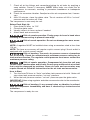
Checking
1. The oil level should be to the middle of
C
B
A
the sight glass (C).
2. If needed remove oil fill plug (A) and
slowly add oil until it reaches the middle
of the sight glass.
Changing
1. Remove the oil fill plug (A).
2. Remove the oil drain plug (B) and drain
oil into a suitable container.
3. Replace the oil drain plug (B) and tight-
en securely.
4. Slowly add compressor oil until the oil
level is in the middle of the sightglass
(C). NOTE:Whenfillingthecrankcase,theoilflowsveryslowlyintothe
pump. If the oil is added too quickly, it will overflow and appear to be full.
16 - ENGN020206
Risk of Unsafe Operation. Overfilling with oil will cause premature
compressor failure. Do not overfill.
5. Replace oil fill plug (A) and tighten securely.
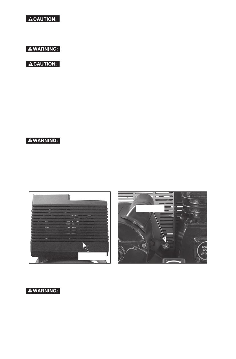
AIR FILTER - INSPECTION AND REPLACEMENT
Hot surfaces. Risk of burn. Compressor heads are exposed
when filter cover is removed. Allow compressor to cool prior to servicing.
Keep the air filter clean at all times. Do not operate the air
compressor with the air filter removed.
A dirty air filter will not allow the compressor pump to operate at full capacity.
Before using the compressor pump, check the air filter to make sure it is clean
and in place.
If it is dirty, replace it with a new filter.
1. Using a pair of needle nose pliers or a screwdriver pull or pry out the old
filter and carefully clean the filter area.
2. Push the new air filter in place.
IMPORTANT: Do not operate the compressor with the air filter removed.
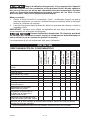
BELT - REPLACEMENT
Risk of personal injury. Serious injury or damage may occur if
parts of the body or loose items get caught in moving parts. Never operate
the outfit with the belt guard removed. The belt guard should be removed only
when the air compressor power is disconnected.
1. Turn air compressor off, lock out the power supply, and relieve all air pres-
sure from the air tank.
2. Remove the front of the belt guard by disengaging the snaps. Insert a flat
bladed screwdriver at each snap location and pry the beltguard apart.
Belt Guard
Wing Nut
3. Loosen the wing nut on hold down plate and tilt motor to allow for easy
removal or installation of the belt.
4. Remove belt.
Risk of moving parts. Use caution when rolling belt onto fly-
wheel, fingers can get caught between the belt and flywheel.
5. Replace belt. NOTE: The belt must be centered over the grooves on the
flywheel and motor pulley.
6. Turn the wing nut on the hold down plate until it makes contact with the
washer, plus one additional turn.
7. Replace the belt guard
.
17 - ENG N020206
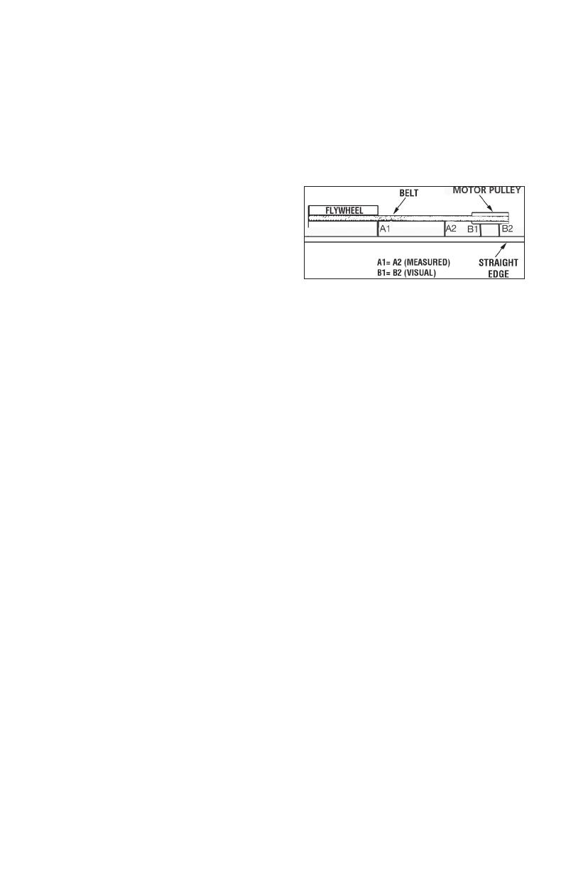
MOTOR PULLEY/FLYWHEEL ALIGNMENT
NOTE: Once the motor pulley has been moved from its factory set location, the
grooves of the flywheel and pulley must be aligned to within 1/16" (1.6 mm) to
prevent excessive belt wear.
The air compressor flywheel and motor pulley must be in-line (in the same plane)
within 1/16" (1.6 mm) to assure belt retention within flywheel belt grooves. To check
alignment, perform the following steps:
1. Turn air compressor off, lock out the power supply, and relieve all air pressure
from the air tank.
2. Remove belt guard.
3. Place a straightedge against the
outside of the flywheel and the motor
drive pulley.
4. Measure the distance between the
edge of the belt and the straightedge
at points A1 and A2 in figure. The
difference between measurements
should be no more than 1/16" (1.6 mm).
5. If the difference is greater than 1/16" (1.6 mm) loosen the set screw holding
the motor drive pulley to the shaft and adjust the pulley’s position on the shaft
until the A1 and A2 measurements are within 1/16" (1.6 mm) of each other.
6. Tighten the motor drive pulley set screw.
7. Visually inspect the motor drive pulley to verify that it is perpendicular to the
drive motor shaft. Points B1 and B2 of Figure should appear to be equal. If
they are not, loosen the setscrew of the motor drive pulley and equalize B1 and
B2, using care not to disturb the belt alignment performed in step 2.
8. Retighten the motor drive pulley setscrew. Torque to 70-100 in-lbs
(7.9-11.3 Nm).
9. Reinstall belt guard.
AIR COMPRESSOR PUMP INTAKE AND EXHAUST VALVES
Once a year have a Trained Service Technician check the air compressor pump
intake and exhaust valves.
INSPECT AIR LINES AND FITTINGS FOR LEAKS
1. Turn air compressor off, lock out the power supply, and relieve all air pressure
from the air tank.
2. Apply a soap solution to all air line fittings and connections/piping.
3. Correct any leaks found.
IMPORTANT: Even minor leaks can cause the air compressor to overwork,
resulting in premature breakdown or inadequate performance.
AIR COMPRESSOR HEAD BOLTS - TORQUING
The air compressor pump head bolts should be kept properly torqued. Check
the torques of the head bolts after the first five hours of operation. Torque to
28–39 ft.-lbs (38.0-52.9 Nm).
18 - ENGN020206
SERVICE AND ADJUSTMENTS
ALL MAINTENANCE AND REPAIR OPERATIONS NOT LISTED MUST BE
PERFORMED BY TRAINED SERVICE TECHNICIAN.
Risk of unsafe operation. Unit cycles automatically when
power is on. When servicing, you may be exposed to voltage sources, com-
pressed air, or moving parts. Before servicing unit unplug or disconnect elec-
trical supply to the air compressor, bleed tank of pressure, and allow the air
compressor to cool.
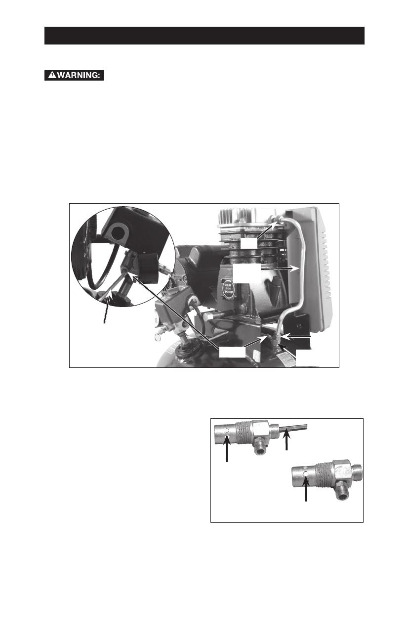
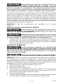
TO REPLACE OR CLEAN CHECK VALVE
1. Release all air pressure from air tank. See To Drain Tank in the Maintenance
section.
2. Turn air compressor off, lock out the power supply, and relieve all air pres-
sure from the air tank.
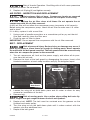
3. Using an adjustable wrench loosen outlet tube nut at air tank and pump.
Carefully move outlet tube away from check valve.
Nut
Pressure
Relief
Tube
Check
Valve
Nut
Outlet
Tube
Nuts
4. Using an adjustable wrench loosen pressure relief tube nut at air tank and
pressure switch. Carefully move pressure relief tube away from check valve.
5. Unscrew the check valve (turn counterclockwise) using a 7/8" open end
wrench. NOTE the orientation for reassembly.
6. Using a screwdriver, carefully push
In closed position
disc is visible.
In open
position
nothing is
visible.
Screwdriver
the valve disc up and down. NOTE:
The valve disc should move freely up
and down on a spring which holds
the valve disc in the closed position,
if not the check valve needs to be
cleaned or replaced.
7. Clean or replace the check valve.
A solvent, such as paint or varnish
remover can be used to clean the
check valve.
8. Apply sealant to the check valve threads. Reinstall the check valve (turn clock-
wise).
9. Replace the pressure release tube. Tighten nuts.
10. Replace the outlet tube and tighten nuts.
11. Perform the Break-in Procedure. See Break-in Procedure in the Operation
section.
19 - ENG N020206
ADDITIONAL SERVICE
Disassembly or service of the air compressor beyond what is covered in this
manual is not recommended. If additional service is required, contact your near-
estAuthorizedWarrantyServiceCenter.
STORAGE
Before you store the air compressor, make sure you do the following:
1. Review the Maintenance section on the preceding pages and perform sched-
uled maintenance as necessary.
2. Set the Auto/Off lever to "Off".
3. Close the globe valve.
4. Remove the air tool or accessory.
5. Open the globe valve and allow the air to slowly bleed from the air tank until
tank pressure is approximately 20 psi.
6. Drain water from air tank by opening drain valve on bottom of tank.
Waterwillcondenseintheairtank.Ifnotdrained,waterwillcor-
rode and weaken the air tank causing a risk of air tank rupture.
7. After the water has been drained, close the drain or drain valve.
NOTE: If drain valve is plugged, release all air pressure. The valve can then be
removed, cleaned, then reinstalled.
8. Protect the air hose from damage (such as being stepped on or run over).
SERVICE
REPLACEMENT PARTS
Use only identical replacement parts. For a parts list or to order parts, visit our
service website at www.deltaportercableservicenet.com. You can also order parts
from your nearest PORTER-CABLE Factory Service Center or PORTER-CABLE
AuthorizedWarrantyServiceCenter.Or,youcancallourCustomerCareCenterat
(888) 848-5175.
SERVICE AND REPAIRS
All quality tools will eventually require servicing and/or replacement of parts. For infor-
mation about PORTER-CABLE, its factory service centers or authorized warranty ser-
vice centers, visit our website at www.deltaportercable.com or call our Customer Care
Center at (888) 848-5175. All repairs made by our service centers are fully guaranteed
against defective material and workmanship. We cannot guarantee repairs made or
attempted by others.
You can also write to us for information at PORTER-CABLE, 4825 Highway 45 North,
Jackson, Tennessee 38305 - Attention: Product Service. Be sure to include all of the
information shown on the nameplate of your tool (model number, type, serial number,
etc.).
ACCESSORIES
Since accessories, other than those offered by PORTER-CABLE, have
not been tested with this product, use of such accessories with this tool could be haz-
ardous. To reduce the risk of injury, only PORTER-CABLE recommended accessories
should be used with this product.
A complete line of accessories is available from your PORTER-CABLE Factory Service
CenteroraPORTERCABLEAuthorizedWarrantyServiceCenter.PleasevisitourWeb
Site www.deltaportercable.com for a catalog or for the name of your nearest supplier.
20 - ENGN020206
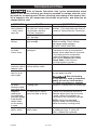
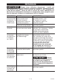
TROUBLESHOOTING
Risk of Unsafe Operation. Unit cycles automatically when
power is on. When servicing, you may be exposed to voltage sources, com-
pressed air, or moving parts. Before servicing unit unplug or disconnect elec-
trical supply to the air compressor, bleed tank of pressure, and allow the air
compressor to cool.
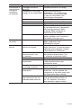
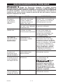
PROBLEM CAUSE CORRECTION
Excessive
tank pressure
- safety valve
pops off
Pressure switch does
not shut off motor when
compressor reaches
"cut-out" pressure.
Move Auto/Off lever to the "Off"
position, if the unit does not shut off
contact a Trained Service Technician.
Pressure switch "cut-
out" too high.
Contact a Trained Service Technician.
Air leaks at
fittings
Tube fittings are not
tight enough.
Tighten fittings where air can be
heard escaping. Check fittings
with soapy water solution.
DO NOT OVER TIGHTEN.
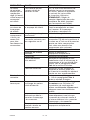
Air leaks at
or inside
check valve
Check valve seat
damaged.
A defective check valve results in
a constant air leak at the pressure
release valve when there is pressure
in the tank and the compressor
is shut off. Replace check valve.
Refer the To Replace or Clean
Check Valve in the Service
and Adjustments section.
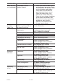
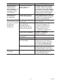
Air leaks at
pressure switch
release valve
Defective pressure
switch release valve.
Contact a Trained Service Technician.
Air leaks in air
tank or at air
tank welds
Defective air tank. Air tank must be replaced.
Do not repair the leak.
Risk of bursting.
Do not drill into, weld or otherwise
modify air tank or it will weaken.
The tank can rupture or explode.
Air leaks
between head
and valve plate
Leaking seal. Contact a Trained Service Technician.
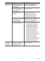
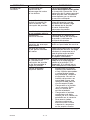
Pressure
reading on
the regulated
pressure gauge
(if equipped)
drops when
an accessory
is used
It is normal for "some"
pressure drop to occur.
If there is an excessive amount of
pressure drop when the accessory
is used, adjust the regulator as
instructed in the Operation section.
NOTE: Adjust the regulated
pressure under flow conditions
(while accessory is being used).
Air leak from
safety valve
Possible defect in
safety valve.
Operate safety valve manually
by pulling on ring. If valve still
leaks, it should be replaced.
Page is loading ...
Page is loading ...
Page is loading ...
Page is loading ...
Page is loading ...
Page is loading ...
Page is loading ...
Page is loading ...
Page is loading ...
Page is loading ...
Page is loading ...
Page is loading ...
Page is loading ...
Page is loading ...
Page is loading ...
Page is loading ...
Page is loading ...
Page is loading ...
Page is loading ...
Page is loading ...
Page is loading ...
Page is loading ...
Page is loading ...
Page is loading ...
Page is loading ...
Page is loading ...
Page is loading ...
Page is loading ...
Page is loading ...
Page is loading ...
Page is loading ...
Page is loading ...
Page is loading ...
Page is loading ...
Page is loading ...
Page is loading ...
Page is loading ...
Page is loading ...
Page is loading ...
Page is loading ...
Page is loading ...
Page is loading ...
Page is loading ...
Page is loading ...
Page is loading ...
Page is loading ...
Page is loading ...
Page is loading ...
Page is loading ...
Page is loading ...
Page is loading ...
Page is loading ...
Page is loading ...
Page is loading ...
Page is loading ...
Page is loading ...
Page is loading ...
Page is loading ...
Page is loading ...
Page is loading ...
-
 1
1
-
 2
2
-
 3
3
-
 4
4
-
 5
5
-
 6
6
-
 7
7
-
 8
8
-
 9
9
-
 10
10
-
 11
11
-
 12
12
-
 13
13
-
 14
14
-
 15
15
-
 16
16
-
 17
17
-
 18
18
-
 19
19
-
 20
20
-
 21
21
-
 22
22
-
 23
23
-
 24
24
-
 25
25
-
 26
26
-
 27
27
-
 28
28
-
 29
29
-
 30
30
-
 31
31
-
 32
32
-
 33
33
-
 34
34
-
 35
35
-
 36
36
-
 37
37
-
 38
38
-
 39
39
-
 40
40
-
 41
41
-
 42
42
-
 43
43
-
 44
44
-
 45
45
-
 46
46
-
 47
47
-
 48
48
-
 49
49
-
 50
50
-
 51
51
-
 52
52
-
 53
53
-
 54
54
-
 55
55
-
 56
56
-
 57
57
-
 58
58
-
 59
59
-
 60
60
-
 61
61
-
 62
62
-
 63
63
-
 64
64
-
 65
65
-
 66
66
-
 67
67
-
 68
68
-
 69
69
-
 70
70
-
 71
71
-
 72
72
-
 73
73
-
 74
74
-
 75
75
-
 76
76
-
 77
77
-
 78
78
-
 79
79
-
 80
80


Black & Decker C7501M User manual
- Category
- Air compressors
- Type
- User manual
- This manual is also suitable for
Ask a question and I''ll find the answer in the document
Finding information in a document is now easier with AI
in other languages
- français: Black & Decker C7501M Manuel utilisateur
- español: Black & Decker C7501M Manual de usuario
Other documents
-
Craftsman 919.165611 Owner's manual
-
-
-
-
-
-
-
-
-