Page is loading ...

WARNING: Improper installation, adjustment, alteration, service or
maintenance can cause personal injury or property damage. Refer
to this manual. For assistance or additional information, contact a
qualied installer, service agency, or the gas supplier.
FOR YOUR SAFETY
Do not store or use gasoline or other ammable vapors and liquid in the
vicinity of this or any other appliance.
FOR YOUR SAFETY
If you smell gas:
1. Open windows.
2. Don’t touch electrical switches.
3. Extinguish any open ame.
4. Immediately call your gas supplier.
Installation and Owner’s Manual
For model N300X - a 2.7 cu. ft., 2-way or 3-way, refrigerator.
The models numbers of 3-way refrigerators contain “.3”. The model numbers of 2-way
refrigerators do not.
The letter “X” in the model number above, stands for a letter or a numeral which means a
refrigerator option.
NORCOLD, Inc.
P.O. Box 4248
Sidney, OH 45365-4248
Part No. 632215A (12-07)
English
Norcold Customer Support Dept.
Telephone: 800-543-1219
Fax: 937-497-3183
Web Site: www.norcold.com
WARNING: DO NOT install this refrigerator in below deck marine
applications. Do not install this refrigerator in xed indoor cabin
or other dwelling applications. This refrigerator must use only
NORCOLD designed and approved outside air intake and exhaust
ventilation for correct and safe operation. Any other ventilation could
cause lethal combustion exhaust fumes and/or explosive propane gas
fumes to be in the living area and/or to be below deck.
!
!

Installation and Owner’s Manual 2
Table of Contents
For dened warranty terms, please see the one page warranty
statement included in the product information packet.
Owner’s Manual ..........................................................................2
Safety Awareness ..................................................................
2
Safety Instuctions ..................................................................
2
About Your Refrigerator .........................................................
3
Storage volume ..............................................................
3
Leveling ..........................................................................
3
Food compartment .........................................................
3
Freezer compartment .....................................................
5
Operation during travel
...................................................3
Door latch for travel and storage ....................................
3
Ignition and Start Up
..............................................................3
Controls ..........................................................................
3
Ignition - propane gas operation ....................................
4
Do a test of the gas safety valve ....................................
4
Start up - AC operation
...................................................4
Start up - DC operation (3-way models only) .................
4
DC operation precautions ..............................................
4
DC operation guidelines .................................................
5
Shut down ......................................................................
5
Effects of High Altitude on Propane Gas Operation ..............
5
Refrigerator Care Checklist ...................................................
5
Defrosting ..............................................................................
5
Cleaning ................................................................................
5
Drip tray ..........................................................................
6
Door Sealing
..........................................................................6
Refrigerator Maintenance Checklist ......................................
6
Refrigerator Storage ..............................................................
6
Refrigerator Maintrenance
.....................................................7
Gas ame appearance ...................................................
7
Remove and clean the burner orice .............................
7
Remove the Refrigerator .......................................................
7
Reinstall the Refrigerator
.......................................................8
Replacement Parts ................................................................
8
Wiring Pictorial ......................................................................
9
Wiring Diagram ......................................................................
9
Installation Manual ...................................................................10
Safety Awareness ................................................................
10
Safety Instructions ...............................................................
10
Certication and Code Requirements .................................
10
Ventilation Requirements ....................................................
11
Assemble the Enclosure
..................................................... 11
Install the Lower and Upper Vents ......................................
11
Install the Refrigerator .........................................................
13
Installation Options ..............................................................
13
Install the decorative door panel ..................................
13
Reverse the door swing ...............................................
13
Connect the Electrical Components ....................................14
Connect the 120 volts AC supply .................................
14
Connect the 12 volts DC supply (3-way models only)
..14
Connect the Propane Gas Components .............................
15
Connect the gas supply system ...................................
15
Examine the gas supply system for leaks ....................
15
WARNING:
- The storage of ammable materials behind or around
the refrigerator creates a re hazard. Do not use the
area behind the refrigerator to store anything, especially
ammable materials (gasoline, cleaning supplies, etc.)
- Do not remove the round ground prong from the
refrigerator AC power cord. Do not use a two prong
adapter or extension cord on the AC power cord.
- A circuit overload can result in an electrical re if the
wires and/or fuses are not the correct size. Either use
the wire and fuse sizes as writtten in the “Installation
Manual” or refer to your local codes or the applicable
RVIA Standards for the correct wire and fuse sizes.
- Incorrect installation, adjustment, change to, or
maintenance of this refrigerator can cause personal
injury, property damage, or both. Have service and
maintenance work done by your dealer or by an Norcold
authorized service center.
- Disconnect both the AC and DC power sources before
doing any maintenance work on the refrigerator. All
service work on this refrigerator must be done by a
qualied service technician.
- Do not bypass or change the refrigerator’s electrical
components or features.
- When you discard an appliance, remove all doors to
prevent accidental entrapment and suffocation.
- Do not spray liquids near electrical outlets, connections,
or the refrigerator components. Many liquids are
electrically conductive and can cause a shock hazard,
electrical shorts, and in some cases re.
Safety Instructions
Read this manual carefully and understand the contents before
you use the refrigerator.
Be aware of possible safety hazards when you see the safety
alert symbol on the refrigerator and in this manual. A signal word
follows the safety alert symbol and identies the danger of the
hazard. Carefully read the descriptions of these signal words to
fully know their meanings. They are for your safety.
WARNING: This signal word means a hazard, which if
ignored, can cause dangerous personal injury, death, or
much property damage.
CAUTION: This signal word means a hazard, which if
ignored, can cause small personal injury or much property
damage.
Safety Awareness
!
!
!

Installation and Owner’s Manual 3
About Your Refrigerator
- The refrigerator cooling system is under pressure. Do
not try to repair or to recharge a defective cooling
system. The cooling system contains sodium chromate.
The breathing of certain chromium compounds can
cause cancer. The cooling system contents can cause
severe skin and eye burns, and can ignite and burn with
an intense ame. Do not bend, drop, weld, move, drill.
puncture, or hit the cooling system.
- At regular intervals, make sure that the refrigerator
ue the burner, the vent areas, and the ventilation air
pathway between the vents are completely free from
any ammable material or blockage. After a period of
storage, it is especially important to check these areas
for any ammable material or blockage caused by
animals.
CAUTION:
- The rear of the refrigerator has sharp edges and
corners. To prevent cuts or abrasions when working on
the refrigerator, be careful and wear cut resistant gloves.
Storage Volume:
This refrigerator is made to store fresh and frozen foods and for
making ice.
Total capacity .....................................................
2.7 cubic feet
Freezer capacity ...................................................
.4 cubic feet
Food compartment capacity
................................ 2.3 cubic feet
Leveling:
CAUTION: The refrigerator is made to operate within
3° off level side-to-side and 6° off level front-to-back (as
looking at the front of the refrigerator). Operating it at more
than these limits can cause damage to the cooling system
and create a risk of personal injury or property damage.
Make sure the vehicle is level before you operate the
refrigerator.
Operation during travel:
While the refrigerator should be level when the vehicle is
stopped, performance during travel is not usually effected.
Food compartment:
Ignite or start up the refrigerator and let it cool for eight hours
before loading with food. If the refrigerator does not start to cool
down after about two hours, contact your dealer or a Norcold
authorized service center.
!
!
Controls:
Thermostat .......................................................................... 96
Selector switch ..................................................................
207
Gas safety valve .................................................................
91
Piezo lighter ......................................................................
216
Flame meter ......................................................................
217
For the best cooling performance:
- Let air move freely inside the entire food compartment.
- Do not cover the shelves with plastic, paper, etc.
To decrease the amount of ice that collects on the cooling ns:
- Cover all liquids and moist foods.
- Let all hot foods cool before putting them in the refrigerator.
- Do not open the door any longer than necessary.
Freezer compartment:
The freezer compartment is made to keep pre-frozen food frozen
and not to quick freeze food. Keep pre-frozen foods in the
freezer compartment.
NOTE: Do not put other items on the ice tray while the water
is freezing. The water freezes more rapidly if the
thermostat is at the coldest temperature setting.
Door latch for travel and storage:
During travel, the door latch prevents the door from opening.
There are no chains, slides, or any devices that you must
engage.
During storage, the door latch prevents the door from completely
closing. Use it to prevent odors when the refrigerator is shut
down for a long period of time.
To use the door latch for storage (See Art00979):
- Open the door just so the door latch [161] is between the ribs
[166] of the latch plate [162].
Ignition and Start Up
1
2
3
4
5
1
5
Art00976
207
96
217
91
216

Installation and Owner’s Manual 4
The thermostat [96] (See Art00976) changes the amount
of propane gas that goes to the burner. This acts as the
temperature control of the refrigerator. Number 5 is the coldest
temperature setting.
When the outside air temperature is below 50° F, the refrigerator
may have a tendency to freeze food at the colder temperature
settings. To reduce the tendency to freeze food:
- Turn the thermostat to a warmer temperature setting.
- Keep the refrigerator full.
- Put foods that are more likely to freeze on the lower shelf.
The selector switch [207] changes the energy source of the
refrigerator between propane gas ( ), AC electric ( ), DC
electric ( ), and OFF ( ).
The gas safety valve [91] is built into the control panel. As long
as a ame is present, the valve is open and allows propane gas
to ow into the burner. Any loss of ame (empty gas tank, blow
out, etc.) closes the safety valve and stops the ow of gas.
The piezo igniter [216] makes a spark which ignites the ame in
the burner.
The ame meter [217] shows if a ame is present in the burner.
Ignition - propane gas operation:
1. Open the valve at the gas storage tank.
2. Turn the thermostat to the 5 position.
3. Turn the selector switch to the propane gas position ( ).
4. Push and hold in the safety valve and push in the igniter
several times in rapid succession, for about ve seconds:
WARNING: Do not hold in the safety valve for more than
30 seconds. If there is no ame in this time, wait at least
ve minutes before you try ignition again. If you continue
to hold in the safety valve, gas will collect in the burner
area. This could cause a re or explosion and result in
dangerous personal injury or death.
- When a ame is present and the ame meter moves into the
green area, release the safety valve.
- If the ame meter does not move into the green area, do this
step again.
5. Turn the thermostat to the temperature setting that you wish.
!
Do a test of the gas safety valve:
With an established ame in GAS mode:
1. Close the manual gas shutoff valve [218] of the refrigerator
(See Art01254].
2. After the ame is extinguished, you should hear a sharp “click”
sound within three minutes.
NOTE: The gas safety valve should close with a sharp “click“
sound.
3. Open the manual gas shutoff valve of the refrigerator.
4. Without pushing in the gas control, push the igniter several
times rapidly in succession. The burner ame should not
ignite. This means that the gas safety valve is working
correctly.
Start up - AC operation:
- Make sure that 120 volts AC is available.
- Turn the selector switch to the AC position ( ).
- Turn the thermostat to the temperature setting that you wish.
Start up - DC operation (3-way models only):
- Make sure that 12 volts DC is available.
- Turn the selector switch to the DC position ( ).
DC operation precautions:
This refrigerator is made to operate on DC power while your
vehicle is “in transit” and AC power or propane gas sources are
not available. Operate the refrigerator on DC power only when
the vehicle engine is running.
For the refrigerator to operate correctly on DC power, the battery
must be maintained in a fully charged condition.
For the battery to be fully charged at all times during refrigerator
operation on DC, the vehicle engine must be running and the
battery charging system must be in good operating condition.
Keep in mind the following electrical precautions for DC operation
of the refrigerator:
- Good battery condition is necessary for correct DC operation.
- The capacity of the battery charging system must be more
than what is necessary for the refrigerator and other DC
appliances.
- While the vehicle engine is running, have a qualied service
technician make sure the voltage of the DC power supply
leads at the refrigerator is more than 11.5 VDC.

Installation and Owner’s Manual 5
Defrosting
Effects of High Altitude on Propane Gas
Operation
When you operate the refrigerator on propane gas at altitudes
higher than 5500 feet above sea level:
- You may experience reduced cooling performance of the
refrigerator.
- You may experience burner outages.
To avoid these possible problems, Norcold recommends that you
operate the refrigerator on AC when at altitudes higher than 5500
feet above sea level.
Refrigerator Care Checklist
Your refrigerator will give you years of trouble free service if you
do these simple checks every three to six months:
- Keep the food compartment and the freezer clean. See
“Cleaning”.
- Defrost the refrigerator as necessary. See “Defrosting”.
- Make sure the door seals correctly. See “Door Sealing“.
A good time to clean the refrigerator is just after you defrost it.
Clean the inside of the refrigerator as often as necessary to avoid
food odors:
Cleaning
DC operation guidelines:
DC operation is intended only to maintain the temperature of the
refrigerator and its contents when they are already cool.
The DC operation is not intended for the initial start up and
cooling of the refrigerator. Always use either the AC operation
or propane gas operation to initially start up and cool the
refrigerator. The refrigerator must be cooled and the temperature
must be steady before you operate the refrigerator on DC.
Keep in mind the following guidelines for DC operation of the
refrigerator:
- Use DC operation of the refrigerator while the vehicle is in
transit.
- Do not use DC operation until the refrigerator and its
contents are completely cooled.
- Only use DC operation if the vehicle battery and battery
charging system are in good operating condition.
Shut down:
- Turn the selector switch to the OFF position ( ).
- Be aware of any cooling changes that are not because of
weather, loading, or thermostat changes. If changes occur,
contact your dealer or service center.
- Make sure the gas supply is propane gas only and is not
butane or a butane mixture.
The cooling ns of the refrigerator operate at below freezing
temperature and will naturally form frost from humidity, which is
always present in the air. The humidity inside the refrigerator
increases:
- with higher outside temperature and humidity.
- with the storage of non-sealed fresh foods or warm foods.
- with the amount of time that the door(s) are open.
- with any air leakage into the refrigerator.
It is normal for frost to collect inside the refrigerator. Excess frost
decreases the cooling performance of the refrigerator. Defrost
the refrigerator as necessary:
- Remove all food from the refrigerator.
- Turn the refrigerator OFF.
NOTE: Defrosting the refrigerator makes excess water inside
the refrigerator.
- Put dry towels (etc.) inside the refrigerator to absorb melted
frost.
CAUTION: High temperatures can cause the inside
surfaces of the refrigerator to warp or melt. Do not
use pans of HOT water, a hair dryer, or any other high
temperature devices to defrost the refrigerator. Do not use
any hard or sharp objects to remove frost. Damage to the
interior of the refrigerator can occur.
- To increase the speed of defrosting, put pans of WARM
water in the refrigerator.
- Remove the wet towels (etc.) and dry the interior.
- Start up the refrigerator.
- Allow the refrigerator to cool down.
- Return all food to the refrigerator.
!

Installation and Owner’s Manual 6
- Remove all food from the refrigerator.
NOTE: Do not use abrasive cleaners, chemicals, or
scouring pads because they can damage the
interior of the refrigerator.
- Wash the interior with a solution of liquid dish detergent and
warm water.
Drip tray:
To remove and clean the drip tray:
- Make sure that the drip tray is empty of water.
- Pull the drip tray forward to remove from the slots in the
refrigerator cabinet.
- Clean the drip tray.
- Push the drip tray back into the original position.
Door Sealing
If the door does not seal correctly, excess frost will collect inside
the refrigerator. Make sure the door seals correctly:
- Close the door on a piece of paper that is about the size of a
dollar bill (See Art00980).
- Gently pull the paper.
- You should feel a slight drag between the gasket and the
cabinet.
- Do this on all four sides of the door.
- If you do not feel a slight drag on the
paper, the door is not sealing correctly:
- Make sure the screws of the hinges are tight.
- Make sure the door gasket does not touch the door
latch:
- If the door gasket touches the door latch,
loosen the screws of the door latch.
- Raise the door latch just so it does not touch
and tighten the screw s of the door latch.
- Make sure the door latch holds the door closed.
Refrigerator Storage
Before the refrigerator is stored for an extended (seasonal)
period of time:
- Defrost and clean the interior of the refrigerator.
- Close the doors with the storage latch.
If the refrigerator is stored for an extended period of time, before
start up:
- Make sure there are no obstructions in the vents, the
ventilation air pathway, the burner, the orice, or the ue
area.
Read and understand the following maintenance sections of this
manual.
NOTE: Norcold is not responsible for installation,
adjustment, alteration, service, or maintenance
performed by anyone other than a qualied RV
dealer or a Norcold authorized service center.
Have a qualied RV dealer or a Norcold authorized service
center do these annual safety and maintenance checks:
- Examine the gas supply lines for leaks.
- Replace or repair if necessary.
- Make sure the propane gas pressure is 11 inches of water
column.
- Adjust if necessary.
- Make sure the combustion seal is complete and intact.
- Replace or repair it if necessary.
- Make sure the burner and the burner orice are clean (See
Art00956).
- Clean if necessary.
- Make sure the electrode spark gap [167] is 1/8 - 3/16 inch
(See Art00955).
- Adjust if necessary.
- Make sure the AC voltage is 108 - 132 volts and the DC
voltage is 10.5 - 15.4 volts.
- Make sure the thermocouple tip is clean and secure.
- Make sure the area at the rear of the refrigerator is free of
any combustible materials, gasoline, and other ammable
vapors and liquids.
Refrigerator Maintenance Checklist

Installation and Owner’s Manual 7
Refrigerator Maintenance
Gas ame appearance:
While in propane gas operation, examine the appearance of the
gas ame:
- Turn the thermostat to the 5 position.
- Open the lower intake vent.
CAUTION: The burner box cover can be hot. Wear
gloves to avoid burns.
- Open the burner box door [165] and look at the gas ame
[75] (See Art00955 and Art01255).
The ame should be:
- a darker blue color on the inside of the ame and a
lighter blue color on the outside of the ame.
- a constant shape without ickering.
- Contact your dealer or Norcold authorized service center
if the ame is:
- yellow
- ickering or changing shape.
- If the ame is yellow or has an erratic and unstable
shape, contact your dealer or Norcold authorized
service center.
- Make sure the ame does not touch the inside of the
ue tube [76].
- If the ame touches the inside of the ue tube, contact
your dealer or Norcold authorized service center.
- Close the burner box door.
Remove and clean the burner orice:
NOTE: Your dealer or Norcold authorized service center must do
this procedure.
To remove and clean the burner orice:
- Close the valve at the gas tank(s).
- Close the manual shut off valve of the refrigerator.
- Turn the selector switch to the OFF position ( ).
- Open the lower intake vent.
!
Remove the Refrigerator
NOTE: Your dealer or Norcold authorized service center must do
this procedure.
CAUTION: The rear of the refrigerator has sharp edges
and corners. To prevent cuts or abrasions when working
on the refrigerator, be careful and wear cut resistant
gloves.
1. Close the valve at the gas tank(s).
WARNING: To avoid possible propane gas leaks, always
use two wrenches to loosen and tighten the gas supply
line at the refrigerator’s manual shut off valve.
2. Open the lower intake vent and remove the gas supply line
from the manual shut off valve of the refrigerator.
CAUTION: The burner box cover can be hot. Wear
gloves to avoid burns.
- Remove the burner box cover by removing one screw.
WARNING: To avoid possible propane gas leaks,
always use two wrenches to loosen and tighten the gas
supply line at the refrigerator’s manual shut off valve.
- Remove the are nut from the orice assembly [77] (See
Art00956).
- Remove the orice assembly from the burner [78].
WARNING: Do not try to remove the orice [79] from
the orice adapter [80] when cleaning. Removal will
damage the orice and seal of the orice and can cause
a propane gas leak. Leaking propane gas can ignite or
explode which can result in dangerous personal injury
or death. Do not clean the orice with a pin or other
objects.a
- Clean the orice assembly with air pressure and alcohol only.
- Using a wrench, assemble the orice assembly to the the
burner.
- Assemble the are nut to the orice assembly.
- Tighten the are nut by hand.
- Hold the orice assembly securely and, using a wrench,
tighten the are nut 1/4 revolution only.
- Examine all of the connections for gas leaks.
!
!
!
!
!

Installation and Owner’s Manual 8
Reinstall the Refrigerator
NOTE: Your dealer or Norcold authorized service center must do
this procedure.
WARNING: Make sure the combustion seal is not
broken, is completely around the refrigerator mounting
anges, and is between the mounting anges and the wall
of the enclosure. If the combustion seal is not complete,
exhaust fumes can be present in the living area of the
vehicle. The breathing of exhaust fumes can cause
dizziness, nausea, and in extreme cases, death.
1. Push the refrigerator completely into the enclosure.
2. Remove the door from the refrigerator.
3. Put the screws though the mounting anges and into the wall.
4. Put the plastic plugs into the mounting anges of the
refrigerator.
5. Attach the door to the refrigerator
CAUTION: The rear of the refrigerator has sharp edges
and corners. To prevent cuts or abrasions when working
on the refrigerator, be careful and wear cut resistant
gloves.
3. Remove the AC power cord from the receptacle.
4. Remove the DC wiring from the refrigerator:
- Remove the DC wiring from the battery or the converter of
the vehicle.
- Put a mark on the DC wires so you can put them back in the
correct location.
- Remove the DC wires from the refrigerator.
5. Remove the screws which fasten the refrigerator to the oor.
6. Remove the plastic plugs from the mounting anges of the
refrigerator.
7. Remove the door from the refrigerator.
8. Remove the screws which fasten the refrigerator to the wall.
9. Remove the refrigerator from the opening.
10. Attach the door to the refrigerator.
!
!
Replacement Parts
You may purchase replacement parts through your local RV
dealer or authorized Norcold Service Center.
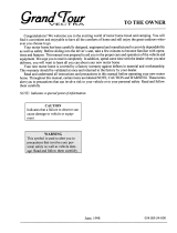
Wiring Pictorial
The parts of the wiring pictorial are (Art01020):
87 ............................................................120VAC Power cord
219 ................................................................... Terminal block
220 ........................................................................ 3 Amp fuse
207 .................................................................. Selector switch
221 ................................................................... Thermocouple
96 ............................................. Thermostat / gas safety valve
222 ..................................................Thermocouple interrupter
217 ...................................................................... Flame meter
92 ............................................................................AC heater
90 .......................-12 VDC Power supply (3-way models only)
99 ......................+12 VDC Power supply (3-way models only)
223 ..................................... 20 Amp fuse (3-way models only)
94 ...........................................DC heater (3-way models only)
6. Open the lower intake vent and put the screws through
refrigerator and into the oor.
WARNING: To avoid possible propane gas leaks, always
use two wrenches to loosen and tighten the gas supply
line at the refrigerator’s manual shut off valve.
7. Attach the gas supply line to the manual shut off valve of the
refrigerator.
8. Open the valve at the gas tank(s).
WARNING: Do not allow the leak checking solution
to touch the electrical components. Many liquids
are electrically conductive and can cause a shock
hazard,electrical shorts, and in some cases re.
9. Examine the gas supply line for leaks.
10. Connect the DC wiring to the refrigerator:
- Install the DC fuse or connect the DC wiring to the battery or
the converter.
- Connect the DC wires from the refrigerator.
11. Connect the AC power cord to the receptacle.
!
!

Installation and Owner’s Manual 9
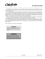
Wiring Diagram
The parts of the wiring diagram are (See Art01021):
87 .............................................................................. 120 VAC
220 ........................................................................ 3 Amp fuse
96 .......................................................................... Thermostat
92 ............................................................................AC heater
87 .............................................................................. 120 VAC
91 ..................................................................Gas safety valve
222 ..................................................Thermocouple interrupter
217 ...................................................................... Flame meter
216 .......................................................................Piezo lighter
167 ..........................................................................Spark gap
99 ............................................ +12 VDC (3-way models only)
223 ..................................... 20 Amp fuse (3-way models only)
94 ...........................................DC heater (3-way models only)
224 ...................................-12 VDC Com (3-way models only)

Installation and Owner’s Manual 10
Safety Instructions
Safety Awareness
Read this manual carefully and understand the contents before
you install the refrigerator.
Be aware of possible safety hazards when you see the safety
alert symbol on the refrigerator and in this manual. A signal word
follows the safety alert symbol and identies the danger of the
hazard. Carefully read the descriptions of these signal words to
fully know their meanings. They are for your safety.
WARNING: This signal word means a hazard, which if
ignored, can cause dangerous personal injury, death, or
much property damage.
CAUTION: This signal word means a hazard, which if
ignored, can cause small personal injury or much property
damage.
WARNING:
- This refrigerator is not approved for use as a free standing
refrigerator. It is equipped for the use of propane gas only
and can not be changed to use any other fuels (natural
gas, butane, etc.).
- Incorrect installation, adjustment, alteration, or
maintenance of this refrigerator can cause personal injury,
property damage, or both.
- Obey the instructions in this manual to install the intake
and exhaust vents.
- Do not install the refrigerator directly on carpet. Put the
refrigerator on a metal or wood panel that extends the full
width and depth of the refrigerator.
- Do not allow anything to touch the refrigerator cooling
system.
- Propane gas can ignite and cause an explosion that can
result in property damage, personal injury, or death. Do
not smoke or create sparks while working on the gas
supply system. Do not use an open ame to examine
the gas supply piping or ttings for leaks. Always use two
wrenches to tighten or loosen the propane gas supply line
connections.
- Make sure the electrical installation obeys all applicable
codes. See “Certication and Code Requirements”
section.
- Do not bypass or change the refrigerator’s electrical
components or features.
- Do not spray liquids near electrical outlets, connections, or
the refrigerator components. Many liquids are electrically
conductive and can cause a shock hazard, electrical
shorts, and in some cases re.
Installation Manual
- The refrigerator cooling system is under pressure. Do not
try to repair or to recharge a defective cooling system.
- The cooling system contains sodium chromate. The
breathing of certain chromium compounds can cause
cancer. The cooling system contents can cause severe
skin and eye burns, and can ignite and burn with an
intense ame. Do not bend, drop, weld, move, drill,
puncture, or hit the cooling system.
CAUTION:
- The rear of the refrigerator has sharp edges and corners.
To prevent cuts or abrasions when working on the
refrigerator, use caution and wear cut resistant gloves.
Certication and Code Requirements
This refrigerator is certied by CSA International as meeting the
latest edition of ANSI Z21.19 / CSA 1.4 standards for installation
in mobile homes or recreational vehicles.
The refrigerator must be installed in accordance with this
“Installation Manual” in order for the Norcold limited warranty
to be in effect. In addition, the installation must conform to the
following, as applicable:
In the United States and Canada:
- Local codes, or in the absence of local codes, the National
Fuel Gas Code, ANSI Z223.1/NFPA 54, the Natural Gas
and Propane installation Code, CSA B149.1, ANSI A119.2
Recreational Vehicles Code, and CSA Z240 RV Series,
Recreational Vehicles.
- A manufactured home (mobile home) installation must
conform with the Manufactured Home Construction and
Safety Standard, Title 24 CFR, Part 3280 [formerly the
Federal Standard for Mobile Home Construction and Safety,
Title 24 (part 280), and the current CSA Z240.4, Gas-
equipped Recreational Vehicles and Mobile Housing.
- If an external power source is utilized, the appliance, when
installed, must be electrically grounded in accordance with
local codes or, in the absence of local codes, the National
Electrical code, and ANSI/NFPA 70, or the Canadian
Electrical Code, CSA C22.2. Parts 1 and 2.
!
!
!
!
Art01290

Installation and Owner’s Manual 11
Assemble the Enclosure
1. Make sure the enclosure is 29.75 - 29.88 inches high x 20.50
- 20.63 inches wide x 21.38 inches deep.
2. Make sure the oor is solid and level.
- The oor must be metal or a wood panel and extend the full
width and depth of the enclosure.
- The oor must be able to support the weight of the
refrigerator and its contents.
3. Make sure there are no adjacent heat sources such as a
furnace vent, a hot water heater vent, etc.
4. If there is more than 1/2 inch between either side of the
refrigerator and the inside of the enclosure:
- Fill the space with berglass (batt-type) insulation or add a
bafe to eliminate the clearance.
- The rear of the batt-type insulation must be between 14
-15 inches from the face of the enclosure.
- Securely attach the batt-type insulation to the enclosure,
so that it remains in this position during refrigerator
installation, if it becomes wet, and in windy conditions.
Install the Lower and Upper Vents
1. Using the following chart, decide which vents and rough
opening (RO) sizes to use.
Certied Vent P/N RO Height RO Width
Upper Roof 622293 24 in. 5 1/4 in.
Exhaust Vent
Upper Side 617485 7 1/4 in. 18 in.
Exhaust Vent
Lower Side 617484 9 3/4 in. 19 3/8 in.
Intake Vent
Universal Upper 620505 6 3/16 in. 17 15/16 in.
and Lower Vent
2. Install the lower intake vent (See Art01629):
NOTE: The lower intake vent is also the service access opening
for the components on the rear of the refrigerator.
Ventilation Requirements
WARNING: The completed installation must:
- Make sure there is sufcient intake of fresh air for
combustion.
- Make sure the living space is completely isolated from
the combustion system of the refrigerator.
- Make sure there is complete and unrestricted ventilation
of the ue exhaust which, in gas mode, can produce
carbon monoxide. The breathing of carbon monoxide
fumes can cause dizziness, nausea, or in extreme
cases, death.
- Make sure the refrigerator is completely isolated from its
heat generating components through the correct use of
bafes and panel construction.
Certied installation needs one lower intake vent and one upper
exhaust vent. Install the upper exhaust vent either through the
roof or through the side wall of the vehicle exactly as written
in this manual. Any other installation method voids both the
certication and the factory warranty of the refrigerator.
The bottom of the opening for the lower intake vent, which is also
the service access door, must be even with or immediately below
the oor level. This allows any leaking propane gas to escape to
the outside and not to collect at oor level.
CSA International certication allows the refrigerator to have
zero (0) inch minimum clearance at the sides, rear, top, and
bottom. While there are no maximum clearances specied for
certication, the following maximum clearances are necessary for
correct refrigerator performance:
Bottom 0 inch min. 0 inch max.
Each Side 0 inch min 1/4 inch max.
Top 0 inch min. 1/4 inch max.
Rear 0 inch min. 1 inch max.
These clearances plus the lower and upper vents cause the
natural air draft that is necessary for good refrigeration. Cooler
air comes in through the lower intake vent, goes up around the
refrigerator coils where it removes the excess heat from the
refrigerator components, and goes out through the upper exhaust
vent. If this air ow is blocked or decreased, the refrigerator will
not cool correctly.
Each NORCOLD model is certied by CSA International for
correct ventilation. Install only the certied vents that are listed in
this manual.
All propane gas supply piping and ttings must obey local, state,
and national codes about type and size. These components
must also obey the current NFPA 501C section 2-4, and in
Canada with the current CAN 1-6.10 Standard.
!

Installation and Owner’s Manual 12
WARNING: Make sure the bottom of the opening of the
lower intake vent is even with or immediately below the
oor level. This allows any leaking propane gas to escape
to the outside and not to collect at oor level.
- Make sure the bottom of the opening of lower intake vent is
even with or immediately below the oor level.
- Align the lower intake vent [9] vertically below the coils [10]
and the condenser [11] of the refrigerator.
3. Install the upper exhaust vent (see Art01630):
- If you install the upper side exhaust vent:
- Make sure the distance [25] from the bottom of the
enclosure to the top of the rough opening for the upper
exhaust vent is at least 37 inches or poor cooling
performance can occur.
- Align the upper exhaust vent [24] horizontally above the
lower intake vent [9] of the refrigerator.
- Install a bafe [13] to prevent stagnant hot air in the area
[14] above the refrigerator.
- Make sure there is less than 1/4 inch clearance [15]
between the bafe and the top of the refrigerator.
- Make sure the bafe is the full width of the inside of
the enclosure.
- If the construction of the vehicle does not allow the
distance [25] to be 37 inches, the distance (optional
only) can be as little as 30 3/4 inches (See Art01633) if
you:
- Install a bent aluminum or galvanized steel sheet
bafe [26] to the rear of the enclosure.
- Make sure that the bend of the bafe is ush with
the bottom edge of the upper exhaust vent opening
- Make sure the bafe is not below the top edge of
the condenser ns.
- Install a bafe [171] from the upper edge of the
lower exhaust vent that is rmly against the
absorber coils [10] of the refrigerator.
- Install a bafe [13] to prevent any stagnant hot air in
the area above the refrigerator.
- If you install the roof exhaust vent (See Art01631):
CAUTION: Make sure that no sawdust, insulation, or
other construction debris is on the refrigerator or in the
enclosure. Debris can cause a combustion hazard and
prevent the refrigerator from operating correctly.
NOTE: Tighten the screws of the roof cap to 10 inch-pounds
max. Also make sure that the air ow around the
upper roof exhaust cap is not blocked or decreased
by other roof mounted features such as a luggage
carrier, an air conditioner, a solar panel, etc.
- If the design of the vehicle allows, install the roof
exhaust vent [12] directly above the condenser [11] of
the refrigerator.
- Install a bafe [13] to prevent stagnant hot air in the
area [14] above the refrigerator.
- Make sure there is less than 1/4 inch clearance
[15] between the bafe and the top of the
refrigerator.
- Make sure the bafe is the full width of the
inside of the enclosure.
- If the design of the vehicle does not allow you to install
the roof exhaust vent directly above the condenser of
the refrigerator (See Art01632):
- Align the roof exhaust vent [12] above the lower
intake vent and move it inboard as necessary.
- Install two bafes [172] to prevent stagnant hot air
in the area [14] above the refrigerator.
- Make sure both bafes are the full width of the
inside of the enclosure.
- Make sure that both bafes are no more than
45° from vertical.
- Put one bafe between the top rear edge of the
refrigerator and the inside edge of the upper
exhaust vent opening.
- Put the other bafe between the outside edge
of the upper exhaust vent opening and the side
wall of the vehicle.
- If there is more than 1 inch of clearance between the
rear of the refrigerator and the enclosure, add two
bafes [171] to the rear of the enclosure (See Art01630,
Art01632 and Art01633):
- Put the bafe at the top edge of the lower intake
vent [9].
- Put the other bafe at the lower edge of the
condenser [11] of the refrigerator.
- Make sure the bafes are less than 1/4 inch
[15] from the coils [10] and condenser of the
refrigerator.
- Make sure the bafes are the full width of the
inside of the enclosure.
!
!

Installation and Owner’s Manual 13
2. Change the position of the hinges:
- Remove and save the plastic bushings that are in the holes
on the ends of the door.
- Remove the screws from the upper hinge [159].
- Put this hinge on the other side as the lower hinge.
- Attach the hinge with the screws.
- Turn the lower hinge pin down into this hinge.
- Remove the screws from the lower hinge [160].
- Remove the screw from the travel latch [161].
- Put this hinge on the other side as the upper hinge.
- Attach the hinge with the screws.
- Push the bushings into the empty holes in the ends of the
door.
3. Change the position of the travel latch (See Art00978 and
Art00979):
- Put the travel latch on the other side of the refrigerator.
- Attach the travel latch with the screw.
- Remove the screw from the travel latch plate [162] on the
door.
- Pull each hinge bushing [74] out of the hole in the door.
- Pull the plastic plug out of the top of the door.
- Push the plastic plug into the other hole in the top of the
door.
- Put the travel latch plate on the other side of the door.
- Attach the travel latch plate with the screw.
- Push each hinge bushing into the hole on the other side of
the door.
4. Install the door:
- Put the door down onto the lower hinge pin.
- Align the holes in the upper hinge and the hinge bushing and
hold in this position.
- Screw the upper hinge pin down into the upper hinge and
into the door.
- Tighten all of the screws.
Install the Refrigerator
Put the refrigerator in position (see Art01253):
WARNING: Make sure the combustion seal [28] is not
broken, is completely around the refrigerator mounting
anges [156], and is between the mounting anges and
the wall of the enclosure. If the combustion seal is not
complete, exhaust fumes can be present in the living area
of the vehicle. The breathing of exhaust fumes can cause
dizziness, nausea, or in extreme cases, death.
- Remove the door from the refrigerator (See “Reverse the
door swing” section).
- Put screws through the holes of the refrigerator mounting
anges and into the enclosure wall.
- Attach the door to the refrigerator.
- Put a screw through the holes [121] in the braces at the
lower rear corners of the refrigerator and into the oor.
Install the decorative door panel:
NOTE: The decorative panels must be 3/16 inch or less in
thickness.
- Make a decorative door panel [38] that is 25 15/16 inches
high x 20 1/8 inches wide (See Art00977).
- Push the decorative door panel into the slots [157] of the
door end caps [158].
- Push each panel retainer [37] into the slot on the edge of the
door.
Reverse the door swing:
This refrigerator has door hinges that allow you to change
the direction that the door opens by moving the hinges to the
opposite corner (See Art00981).
1. Remove the door:
- Turn out and save the upper hinge pin [63].
- Open the door a small amount and pull the top of the door
away from the upper hinge of the refrigerator.
- Lift the door off of the lower hinge pin [64].
- Turn out and save the lower hinge pin.
Installation Options
!

Installation and Owner’s Manual 14
Connect the Electrical Components
AC Operation 120 volts AC voltage
(108 volts min. - 132 volts max.)
Current Draw 1.4 Amps at 110 Volts AC
1.5 Amps at 120 Volts AC
DC Operation 12 volts DC voltage
(3-way models only) (11.5 volts min. - 15.4 volts max.)
Current Draw 12 Amps at 12 Volts DC
14 Amps at 14 Volts DC
This refrigerator operates on these electrical sources. Operation
out of these limits may damage the refrigerator’s electrical circuit
parts and will void the warranty.
WARNING: The rear of the refrigerator cooling system
has hot surfaces and sharp surfaces that can damage
electrical wiring. Make sure that there is a good clearance
between all electrical wiring and the cooling system of
the refrigerator. Position any electrical wiring within the
refrigerator enclosure opposite the burner side of the
refrigerator. Do not put any electrical wiring through the
roof exhaust vent. Failure to correctly position electrical
wiring can result in electrical shock or re.
Connect the 120 volts AC supply:
WARNING: Connect the AC power cord only to a
grounded three-prong receptacle. Do not remove the
round ground prong from the power cord. Do not use a
two-prong adapter or an extension cord. Operation of the
refrigerator without correct ground can cause dangerous
electrical shock or death if you are touching the metal
parts of the refrigerator.
Put the AC power cord into a grounded three-prong receptacle:
- Make sure the receptacle is positioned within easy reach of
the lower intake vent.
- Make sure the power cord does not touch the burner cover,
the ue pipe, or any hot component that could damage the
insulation of the power cord.
- Make sure the travel latch engages the travel latch plate.
- If not, loosen the screw and adjust the height of the
travel latch plate.
- Tighten the screw.
Connect the 12 volts DC supply (3-way models only):
As the distance from the vehicle battery to the refrigerator
increases, the correct AWG wire size and fuse size also
increases. If the wire size is too small for the distance, a voltage
drop occurs. The voltage drop decreases the output of the
system heater and causes decreased cooling performance.
1. Determine the min. wire size and the max. fuse size to use:
WARNING: If you use an incorrect wire size and/or fuse
size, electrical re can result.
- Measure the distance from the vehicle battery to the
refrigerator:
- If the distance is 0 - 20 feet, use a minimum of 12 AWG
wire and a maximum 20 amp fuse.
- If the distance is more than 20 feet, use a minimum 10
AWG wire and a maximum 30 amp fuse.
- If the wire size is larger than the min. size, use the correct
fuse per RVIA A119.2 standard or local codes.
The wire connections must be clean, tight and free of corrosion.
If any of these items are not correct:
- A voltage drop to the refrigerator will occur.
- The voltage drop will reduce the cooling performance of the
refrigerator.
The terminals for connecting the DC power supply are marked
positive (+) and negative (-) on the terminal block of the
refrigerator. Make sure that:
- Each DC power supply wire is attached to the correct polarity
terminal.
- The chassis or the vehicle frame is not used as one of the
conductors.
- The DC power supply wires including the fuses are routed
directly from the battery to the refrigerator.
2. Connect the D.C. power supply wires:
- Attach a 1/4 inch female Quick Connect terminal to each DC
power supply wire.
- Push each power wire onto the terminal block [219] at the
rear of the refrigerator (See Art01254).
- Make sure each DC power supply wire is on the correct
polarity terminal.
!
!
!

Installation and Owner’s Manual 15
Connect the Propane Gas Components
This refrigerator operates on propane gas at a pressure of 11
inches Water Column Propane.
Connect the propane gas supply system:
WARNING: Be very careful when working on or near the
propane gas system.
- Do not smoke or use an open ame near the propane
gas system.
- Do not use an open ame to examine for leaks.
- Do not connect the refrigerator to the gas tank without a
pressure regulator between them.
- To avoid an propane gas leak, always use two wrenches
to tighten or loosen the gas supply line connections.
- Leaking propane gas can ignite or explode and result in
dangerous personal injury or death.
Connect the gas supply line to the refrigerator:
- Make sure all tubing and ttings obey all local, state, and
national codes about size and type.
- Make sure that all exible metal connectors obey the current
CAN1-6.10 Standard.
- Make sure that the materials used for the gas supply line
obey both the current ANSI A 119.2 (NFPA 1192) and
CSA Z240 Standards on Recreational Vehicles. Norcold
recommends the use of 3/8 inch copper tubing as the gas
supply line and requires a 3/8 inch SAE (UNF 5/8-18) male
are tting as the connection to the refrigerator.
- Put the propane gas supply line up through the oor of the
enclosure.
- Make sure the hole through the oor is large enough to allow
clearance for the gas supply line.
- Put a weather resistant seal (grommet, sealant, etc.) around
the gas supply line where it goes through the oor to prevent
vibration and abrasion.
- To prevent vibration and abrasion, make sure that the gas
supply line is not against anything in the enclosure.
- Attach the gas supply line to the bulkhead ting [2] of the
refrigerator (See Art01254).
Examine the gas supply system for leaks:
WARNING: Do not allow the leak detecting solution
to touch the electrical components. Many liquids are
electrically conductive and can cause a shock hazard,
electrical shorts, and in some cases, re.
Use a leak detecting solution to examine the gas supply line and
all propane gas connections for leaks..
If you use compressed air for the test:
- The pressure at the manual shut off valve of the refrigerator
must not be more than 1/2 psig (14 inches Water Column).
- If the air pressure is more than 1/2 psig (14 inches Water
Column), remove the gas supply line from the bulkhead
tting of the refrigerator before the test.
- If the air pressure is equal to or less than 1/2 psig (14
inches Water Column), close the manual shutoff valve of the
refrigerator before the test.
!
!

87
Art01020
219
92
94
221
220
223
99
90
207
222
217
96
W1
W4
W3
W2
AC1
DC3
AC2
DC2
G3
YEL / JUANE
YEL / JUANE
BLU / BLEU
BLU / BLEU
BLK /
NOIR
BLK(RIB) /
NOIR
(CANN.)
GRN-YEL / VERT-JUANE
BLK / NOIR
BRN /
BRUN
RED / ROUGE
BLU / BLEU
RED /
ROUGE
BLU /
BLEU
BLK / NOIR
WHT / BLANC
1
2
3
4
8
7
65
DC/CC
G3
AC/CA
GAS/GAZ
OFF/ARRET
M
DC/CC
AC/CA
GAS/GAZ
OFF/ARRET
DC3
W3
W4
DC2
DC/CC
AC/CA
GAS/GAZ
OFF/ARRET
W2
AC1
DC/CC
AC/CA
GAS/GAZ
OFF/ARRET
W1
87
99
91
220
223
217
222
96
92
87
94
224
216
167
Art01021
/