Page is loading ...

Motherboard
PRIME B360M-A

ii
E13793
First Edition
February 2018
Copyright © 2018 ASUSTeK COMPUTER INC. All Rights Reserved.
No part of this manual, including the products and software described in it, may be reproduced,
transmitted, transcribed, stored in a retrieval system, or translated into any language in any form or by any
means, except documentation kept by the purchaser for backup purposes, without the express written
permission of ASUSTeK COMPUTER INC. (“ASUS”).
Product warranty or service will not be extended if: (1) the product is repaired, modied or altered, unless
such repair, modication of alteration is authorized in writing by ASUS; or (2) the serial number of the
product is defaced or missing.
ASUS PROVIDES THIS MANUAL “AS IS” WITHOUT WARRANTY OF ANY KIND, EITHER EXPRESS
OR IMPLIED, INCLUDING BUT NOT LIMITED TO THE IMPLIED WARRANTIES OR CONDITIONS OF
MERCHANTABILITY OR FITNESS FOR A PARTICULAR PURPOSE. IN NO EVENT SHALL ASUS, ITS
DIRECTORS, OFFICERS, EMPLOYEES OR AGENTS BE LIABLE FOR ANY INDIRECT, SPECIAL,
INCIDENTAL, OR CONSEQUENTIAL DAMAGES (INCLUDING DAMAGES FOR LOSS OF PROFITS,
LOSS OF BUSINESS, LOSS OF USE OR DATA, INTERRUPTION OF BUSINESS AND THE LIKE),
EVEN IF ASUS HAS BEEN ADVISED OF THE POSSIBILITY OF SUCH DAMAGES ARISING FROM ANY
DEFECT OR ERROR IN THIS MANUAL OR PRODUCT.
SPECIFICATIONS AND INFORMATION CONTAINED IN THIS MANUAL ARE FURNISHED FOR
INFORMATIONAL USE ONLY, AND ARE SUBJECT TO CHANGE AT ANY TIME WITHOUT NOTICE,
AND SHOULD NOT BE CONSTRUED AS A COMMITMENT BY ASUS. ASUS ASSUMES NO
RESPONSIBILITY OR LIABILITY FOR ANY ERRORS OR INACCURACIES THAT MAY APPEAR IN THIS
MANUAL, INCLUDING THE PRODUCTS AND SOFTWARE DESCRIBED IN IT.
Products and corporate names appearing in this manual may or may not be registered trademarks or
copyrights of their respective companies, and are used only for identication or explanation and to the
owners’ benet, without intent to infringe.
Offer to Provide Source Code of Certain Software
This product contains copyrighted software that is licensed under the General Public License (“GPL”),
under the Lesser General Public License Version (“LGPL”) and/or other Free Open Source Software
Licenses. Such software in this product is distributed without any warranty to the extent permitted by the
applicable law. Copies of these licenses are included in this product.
Where the applicable license entitles you to the source code of such software and/or other additional data,
you may obtain it for a period of three years after our last shipment of the product, either
(1) for free by downloading it from http://support.asus.com/download
or
(2) for the cost of reproduction and shipment, which is dependent on the preferred carrier and the location
where you want to have it shipped to, by sending a request to:
ASUSTeK Computer Inc.
Legal Compliance Dept.
15 Li Te Rd.,
Beitou, Taipei 112
Taiwan
In your request please provide the name, model number and version, as stated in the About Box of the
product for which you wish to obtain the corresponding source code and your contact details so that we
can coordinate the terms and cost of shipment with you.
The source code will be distributed WITHOUT ANY WARRANTY and licensed under the same license as
the corresponding binary/object code.
This offer is valid to anyone in receipt of this information.
ASUSTeK is eager to duly provide complete source code as required under various Free Open Source
Software licenses. If however you encounter any problems in obtaining the full corresponding source
code we would be much obliged if you give us a notication to the email address [email protected], stating
the product and describing the problem (please DO NOT send large attachments such as source code
archives, etc. to this email address).

iii
Contents
Safety information ...................................................................................... iv
About this guide ......................................................................................... iv
Package contents ....................................................................................... vi
PRIME B360M-A specifications summary ................................................ vi
Chapter 1 Product introduction
Motherboard overview ............................................................................. 1-1
Central Processing Unit (CPU) ................................................................ 1-7
System memory ........................................................................................ 1-8
Chapter 2 BIOS information
BIOS setup program ................................................................................. 2-1
EZ Mode ..................................................................................................... 2-2
Advanced Mode ........................................................................................ 2-3
Exit menu ................................................................................................... 2-4
Appendix
Notices .......................................................................................................A-1
ASUS contact information .......................................................................A-5

iv
Safety information
Electrical safety
• To prevent electrical shock hazard, disconnect the power cable from the electrical outlet
before relocating the system.
• When adding or removing devices to or from the system, ensure that the power cables
for the devices are unplugged before the signal cables are connected. If possible,
disconnect all power cables from the existing system before you add a device.
• Before connecting or removing signal cables from the motherboard, ensure that all
power cables are unplugged.
• Seek professional assistance before using an adapter or extension cord. These devices
could interrupt the grounding circuit.
• Ensure that your power supply is set to the correct voltage in your area. If you are not
sure about the voltage of the electrical outlet you are using, contact your local power
company.
• If the power supply is broken, do not try to x it by yourself. Contact a qualied service
technician or your retailer.
Operation safety
• Before installing the motherboard and adding components, carefully read all the manuals
that came with the package.
• Before using the product, ensure all cables are correctly connected and the power
cables are not damaged. If you detect any damage, contact your dealer immediately.
• To avoid short circuits, keep paper clips, screws, and staples away from connectors,
slots, sockets and circuitry.
• Avoid dust, humidity, and temperature extremes. Do not place the product in any area
where it may be exposed to moisture.
• Place the product on a stable surface.
• If you encounter technical problems with the product, contact a qualied service
technician or your retailer.
About this guide
This user guide contains the information you need when installing and conguring the
motherboard.
How this guide is organized
This guide contains the following parts:
• Chapter1:Productintroduction
This chapter describes the features of the motherboard and the new technology it
supports. It includes descriptions of the switches, jumpers, and connectors on the
motherboard.
• Chapter2:BIOSinformation
This chapter discusses changing system settings through the BIOS Setup menus.
Detailed descriptions for the BIOS parameters are also provided.
v
Where to find more information
Refer to the following sources for additional information and for product and software
updates.
1. ASUS websites
The ASUS website provides updated information on ASUS hardware and software
products. Refer to the ASUS contact information.
2. Optional documentation
Your product package may include optional documentation, such as warranty yers,
that may have been added by your dealer. These documents are not part of the
standard package.
Conventions used in this guide
To ensure that you perform certain tasks properly, take note of the following symbols used
throughout this manual.
DANGER/WARNING: Information to prevent injury to yourself when
completing a task.
CAUTION: Information to prevent damage to the components when
completing a task
IMPORTANT: Instructions that you MUST follow to complete a task.
NOTE: Tips and additional information to help you complete a task.
Typography
Bold text Indicates a menu or an item to select.
Italics
Used to emphasize a word or a phrase.
<Key> Keys enclosed in the less-than and greater-than sign
means that you must press the enclosed key.
Example: <Enter> means that you must press the Enter or
Return key.
<Key1> + <Key2> + <Key3> If you must press two or more keys simultaneously, the key
names are linked with a plus sign (+).

vi
PRIME B360M-A specifications summary
(continued on the next page)
Package contents
Check your motherboard package for the following items.
Motherboard
ASUS PRIME B360M-A motherboard
Cables
2 x Serial ATA 6.0 Gb/s cables
Accessories
1 x I/O Shield
1 x M.2 screw package
Application DVD
1 x Support DVD
Documentation
1 x User Manual
If any of the above items is damaged or missing, contact your retailer.
CPU
LGA1151 socket for 8
th
Generation Intel
®
Core™ i7/ i5/ i3, Pentium
®
and Celeron
®
processors
Supports Intel
®
14nm CPU
Supports Intel
®
Turbo Boost Technology 2.0*
* The Intel
®
Turbo Boost Technology 2.0 support depends on the CPU types.
** Refer to www.asus.com for Intel
®
CPU support list.
Chipset
Intel
®
B360 Chipset
Memory
4x DIMMs, max 64 GB, DDR4 2666/ 2400/ 2133 MHz, non-ECC, un-buffered memory
Dual-channel memory architecture
Supports Intel
®
Extreme Memory Prole (XMP)
* The maximum memory frequency supported varies by processor.
** DDR4 2666MHz and higher memory modules will run at max. 2666MHz on Intel
®
8
th
Generation 6-core or higher processors.
*** Refer to www.asus.com for the latest Memory QVL (Qualified Vendors List).
Expansion
slots
1 x PCI Express 3.0/2.0 x16 slot (at x 16 mode)
2 x PCI Express 3.0/2.0 x1 slots
Graphics
Integrated graphics processor - Intel
®
HD Graphics support
Multi-VGA output support: HDMI, DVI-D, D-sub ports
- Supports HDMI 1.4b with max. resolution 4096 x 2160@24Hz / 2560 x
1600@60Hz
- Supports DVI-D with maximum resolution of 1920 x 1200 @60Hz
- Supports D-sub with maximum resolution of 1920 x 1200 @60Hz
Supports Intel
®
InTru™ 3D / Quick Sync Video/Clear Video HD Technology / Insider™
Supports up to 3 displays simultaneously
Maximum shared memory of 1024MB (for iGPU exclusively)

vii
PRIME B360M-A specifications summary
(continued on the next page)
Storage
Intel
®
B360 Chipset
- 1 x M.2_1 Socket 3 with M key, type 2242/2260/2280 storage devices support
(both SATA & PCIE 3.0 x 4 mode)*
- 1 x M.2_2 Socket 3 with M key, type 2242/2260/2280 storage devices support
(PCIE 3.0 x 4 mode)
- 6 x SATA 6.0 Gb/s ports (gray)
- Intel
®
Optane™ Memory Ready**
* When a device in SATA mode is installed on the M.2_1 socket, SATA_2 port cannot be
used.
** Only the M.2_2 socket can support Intel
®
Optane
TM
memory.
LAN
Realtek
®
8111H Gigabit LAN supports LANGuard
Audio
Realtek
®
ALC887 8-channel High Denition Audio CODEC
- LED-illuminated design: Brighten up your build with the gorgeous illuminated
audio trace path
- Audio Shielding: Ensures precision analog/digital separation and greatly reduces
multi-lateral interference
- Dedicated audio PCB layers: Separate layers for left and right channels to guard
the quality of the sensitive audio signals
- Premium Japanese audio capacitors: Provide warm, natural and immersive
sound with exceptional clarity and delity
- Supports jack-detection and front panel jack-retasking
USB
Intel
®
B360 Chipset
- 2 x USB 3.1 Gen 2 (up to 10Gbps) ports (2 ports @back panel, teal blue, Type A)
- 3 x USB 3.1 Gen 1 (up to 5Gbps) ports (2 ports @mid-board, 1 port @back panel,
Type C)
- 6 x USB 2.0/1.1 ports (4 ports @mid-board, 2 ports @back panel, black, Type A)
ASUS unique
features
ASUS 5X PROTECTION III
- ASUS SafeSlot Core - Fortied PCIe Slot prevents damage
- ASUS LANGuard: Protects against LAN surges, lightning strikes and static-
electricity discharges!
- ASUS Overvoltage Protection: World-class circuit-protecting power design
- ASUS Stainless-Steel Back I/O: 3X corrosion-resistance for greater durability!
- ASUS DIGI+ VRM: 5 Phase digital power design
Superb Performance
ASUS OptiMem
- Improved DDR4 stability
M.2 Onboard
- The latest transfer technologies with up to 32Gb/s data transfer speeds
ASUS Fan Xpert 2+
- Ultimate cooling and quietness
ASUS EPU
- EPU
UEFI BIOS
- Most advanced options with fast response time

viii
PRIME B360M-A specifications summary
ASUS unique
features
Gaming Scenario
Audio Features
- Audio that roars on the battleeld
ASUS Exclusive Features
- ASUS Ai Charger
- ASUS AI Suite 3
- ASUS File Transfer
- ASUS PC Cleaner
EZ DIY
UEFI BIOS EZ Mode
- Featuring friendly graphics user interface
- ASUS CrashFree BIOS 3
- ASUS EZ Flash 3
Q-Design
- ASUS Q-DIMM
ASUS Quiet
Thermal
Solution
Quiet Thermal Design
- ASUS Fan Xpert 2+
- Stylish Fanless Design: PCH Heat-sink
Rear panel I/O
ports
1 x PS/2 keyboard port (purple)
1 x PS/2 mouse port (green)
1 x DVI-D port
1 x D-sub port
1 x HDMI port
2 x USB 3.1 Gen 2 (up to 10Gbps) ports (Type A, teal blue)
1 x USB 3.1 Gen 1 (up to 5Gbps) port (Type C)
2 x USB 2.0/1.1 ports
1 x LAN (RJ45) port
3 Audio jacks support 8 channel*
* Use a chassis with HD audio module in the front panel to support an 8-channel
audio output.
Internal
connectors
1 x USB 3.1 Gen 1 (up to 5Gbps) connector support additional 2 USB ports
(19-pin)
2 x USB 2.0/1.1 connectors support additional 4 USB ports
6 x SATA 6.0Gb/s connectors (gray)
2 x M.2 Socket 3 (for M Key, type 2242/2260/2280 devices)
1 x CPU Fan connector
2 x Chassis Fan connectors (4-pin) for both 3-pin(DC mode) and 4-pin (PWM
mode) coolers control
1 x Front panel audio connector (AAFP)
1 x System panel connector
1 x Speaker connector
1 x S/PDIF out header
1 x Clear CMOS header
(continued on the next page)

ix
Specications are subject to change without notice.
PRIME B360M-A specifications summary
Internal
connectors
1 x 24-pin EATX Power connector
1 x 8-pin EATX 12V Power connector
1 x COM header
1 x LPT header
1 x TPM header
1 x Chassis Intrusion header
1 x Aura RGB Strip header
BIOS features
128Mb Flash ROM, UEFI AMI BIOS, PnP, SM BIOS 3.1, ACPI 6.1, Multi-
language BIOS, ASUS EZ Flash 3, CrashFree BIOS 3, F3 My Favorites, Last
Modied log, F4 AURA ON/OFF, F6 Qfan Control, F9 Search, F12 PrintScreen,
and ASUS DRAM SPD (Serial Presence Detect) memory information
Manageability
WOL by PME, PXE
Support DVD
Drivers
ASUS utilities
EZ Update
Anti-virus software (OEM version)
OS support
Windows
®
10 ( 64-bit)
Form factor mATX Form Factor, 9.6”x 8.1” (24.4cm x 20.6cm)

ASUS PRIME B360M-A
1-1
Product introduction
1
Motherboard overview
• Unplugthepowercordfromthewallsocketbeforetouchinganycomponent.
• Beforehandlingcomponents,useagroundedwriststraportouchasafelygrounded
objectorametalobject,suchasthepowersupplycase,toavoiddamagingthemdue
tostaticelectricity.
• Beforeyouinstallorremoveanycomponent,ensurethattheATXpowersupplyis
switchedofforthepowercordisdetachedfromthepowersupply.Failuretodoso
maycauseseveredamagetothemotherboard,peripherals,orcomponents.
• Unplugthepowercordbeforeinstallingorremovingthemotherboard.Failuretodoso
cancauseyouphysicalinjuryanddamagetomotherboardcomponents.
Place this
side towards
the rear of the
chassis
ScantheQRcodetogetthedetailedpindenitions.
PRIME B360M-A
M.2_1(SOCKET3)
PCIE SATA IRST
X4 V X
M.2_2(SOCKET3)
PCIE SATA IRST
X4 X V
PCIEX16
PCIEX1_1
PCIEX1_2
SPEAKER
TPM
RGB_HEADER
F_PANEL
SPDIF_OUT
CLRTC
USB1011
USB914
U31G1_56
AAFP
COM
LPT
EATXPWR
CHA_FAN2
CPU_FAN
CHA_FAN1
BATTERY
Super
I/O
ALC
887
DIGI
+VRM
DDR4 DIMM_B1 (64bit, 288-pin module)
LGA1151
2280 2260 2242
2280 2260 2242
M.2_1(SOCKET3)
M.2_2(SOCKET3)
DDR4 DIMM_B2* (64bit,288-pin module)
DDR4 DIMM_A1 (64bit, 288-pin module)
DDR4 DIMM_A2* (64bit,288-pin module)
20.6cm(8.1in)
128Mb
BIOS
SATA6G_3
SATA6G_2
SATA6G_1
SATA6G_5SATA6G_6 SATA6G_4
Intel
®
B360
Realtek
8111H
24.4cm(9.6in)
AUDIO
LAN_USB78
U31G2_12
HDMI
U31G1_C3
DVI
VGA
KBMS
EATX12V
1 422 3
1
8101112
1
1
5
1
6
1
8
1
7
19
131415161718
20
9
8
CHASSIS
1-2
Chapter 1: Product introduction
ATX power connectors (24-pin EATXPWR, 8-pin EATX12V)
CorrectlyorienttheATXpowersupplyplugsintotheseconnectorsandpushdown
rmlyuntiltheconnectorscompletelyt.
•
Forafullyconguredsystem,werecommendthatyouuseapowersupplyunit
(PSU)thatcomplieswithATX12VSpecication2.0(orlaterversion)andprovides
aminimumpowerof350W.ThisPSUtypehas24-pinand8-pinpowerplugs.
• WerecommendthatyouuseaPSUwithhigherpoweroutputwhen
conguringasystemwithmorepower-consumingdevicesorwhenyou
intendtoinstalladditionaldevices.Thesystemmaybecomeunstableor
maynotbootupifthepowerisinadequate.
•
Ifyouareuncertainabouttheminimumpowersupplyrequirementforyoursystem,
refertotheRecommendedPowerSupplyWattageCalculatorathttp://support.
asus.com.cn/PowerSupply.aspx?SLanguage=enfordetails.
CPU and chassis fan connectors (4-pin CPU_FAN, 4-pin CHA_FAN 1/2)
Connectthefancablestothefanconnectorsonthemotherboard,ensuringthatthe
blackwireofeachcablematchesthegroundpinoftheconnector.
Donotforgettoconnectthefancablestothefanconnectors.Insufcientairowinside
thesystemmaydamagethemotherboardcomponents.Thesearenotjumpers!Donot
placejumpercapsonthefanconnectors!TheCPU_FANconnectorsupportsaCPUfan
ofmaximum1A(12W)fanpower.
Intel
®
LGA1151 CPU socket
InstallIntel
®
LGA1151CPUintothissurfacemountLGA1151socket,whichisdesigned
for8
th
GenerationIntel
®
Core™i7/i5/i3,Pentium
®
andCeleron
®
processors.
Formoredetails,refertoCentral Processing Unit (CPU).
DDR4 DIMM slots
Install2GB,4GB,8GB,and16GBunbufferednon-ECCDDR4DIMMsintothese
DIMMsockets.
Formoredetails,refertoSystem memory.
USB 3.1 Gen1 (up to 5Gbps) connector (20-1 pin U31G1_56)
ConnectaUSB3.1Gen1moduletothisconnectorforadditionalUSB3.1Gen1
frontorrearpanelports.ThisconnectorcomplieswithUSB3.1Gen1specications
andprovidefasterdatatransferspeedsofupto5Gbps,fasterchargingtimefor
USB-chargeabledevices,optimizedpowerefciency,andbackwardcompatibility
withUSB2.0.
M.2 socket 3
ThesesocketsallowyoutoinstallM.2(NGFF)SSDmodules.
• TheseM.2socketssupportMKeyand2242/2260/2280storage
devices.
• BothM.2socketscansupportdatatransferspeedupto32Gb/s.
• OnlytheM.2_2socketcansupportIntel
®
Optane
TM
memory.
• OnlytheM.2_1socketcansupportSATAmodestorage
devices.WhenadeviceinSATAmodeisinstalledontheM.2_1
socket,SATA_2isdisabled.
M.2(SOCKET3)
ASUS PRIME B360M-A
1-3
TPM connector (14-1 pin TPM)
ThisconnectorsupportsaTrustedPlatformModule(TPM)system,whichcan
securelystorekeys,digitalcerticates,passwordsanddata.ATPMsystem
alsohelpsenhancenetworksecurity,protectsdigitalidentities,andensures
platformintegrity.
Intel
®
B360 Serial ATA 6.0Gb/s connectors (7-pin SATA6G_1~6)
TheseconnectorsconnecttoSerialATA6.0Gb/sharddiskdrivesviaSerial
ATA6.0Gb/ssignalcables.
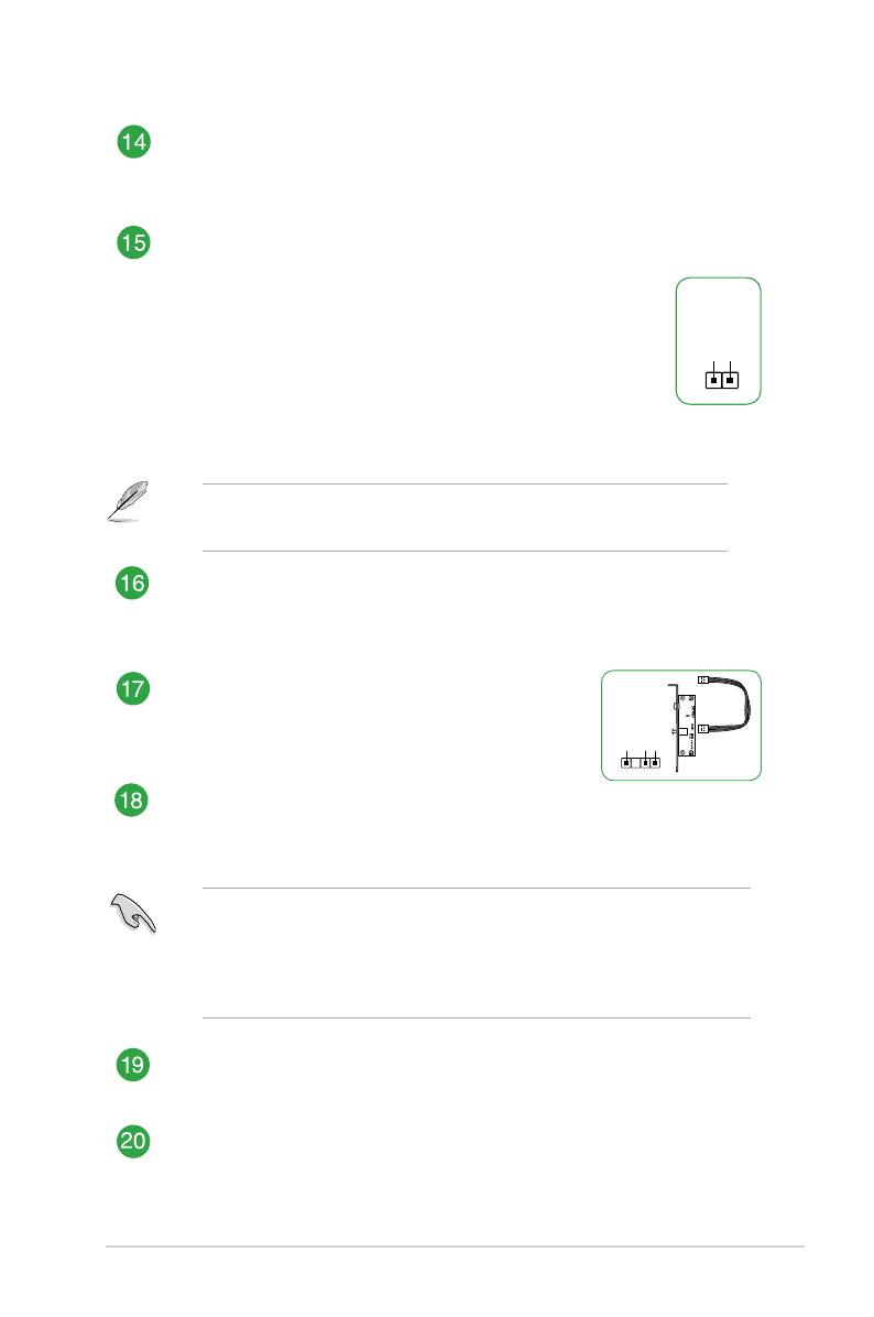
Chassis intrusion header (4-1 pin CHASSIS)
Thisheaderisforachassis-mountedintrusiondetectionsensororswitch
Connectoneendofthechassisintrusionsensororswitchcabletothis
header.Thechassisintrusionsensororswitchsendsahigh-levelsignaltothis
headerwhenachassiscomponentisremovedorreplaced.Thesignalisthen
generatedasachassisintrusionevent.
Bydefault,thepinlabeled“ChassisSignal”and“Ground”areshortedwitha
jumpercap.Removethejumpercapsonlywhenyouintendtousethechassis
intrusiondetectionfeature.
System panel connector (10-1 pin F_PANEL)
Thisconnectorsupportsseveralchassis-mountedfunctions.
Speaker connector (4-pin SPEAKER)
This4-pinconnectorisforthechassis-mountedsystemwarningspeaker.The
speakerallowsyoutohearsystembeepsandwarnings.
USB 2.0 connectors (10-1 pin USB914, USB1011)
ConnecttheUSBmodulecabletoanyoftheseconnectors,theninstallthe
moduletoaslotopeningatthebackofthesystemchassis.TheseUSB
connectorscomplywithUSB2.0specicationsandsupportupto480Mbps
connectionspeed.
RGB header (4-pin RGB_HEADER)
ThisheaderisforRGBLEDstrips.
TheRGBheadersupports5050RGBmulti-colorLEDstrips(12V/G/R/B),witha
maximumpowerratingof3A(12V),andnolongerthan3m.
Beforeyouinstallorremoveanycomponent,ensurethattheATXpowersupplyis
switchedofforthepowercordisdetachedfromthepowersupply.Failuretodoso
maycauseseveredamagetothemotherboard,peripherals,orcomponents.
• ActuallightingandcolorwillvarywithLEDstrip.
• IfyourLEDstripdoesnotlightup,checkiftheRGBLEDextensioncable
andtheRGBLEDstripisconnectedinthecorrectorientation,andthe12V
connectorisalignedwiththe12Vheaderonthemotherboard.
• TheLEDstripwillonlylightupwhenthesystemisoperating.
• TheLEDstripsarepurchasedseparately.
1-4
Chapter 1: Product introduction
Serial port connector (10-1 pin COM)
Thisconnectorisforaserial(COM)port.Connecttheserialportmodulecableto
thisconnector,theninstallthemoduletoaslotopeningatthebackofthesystem
chassis.
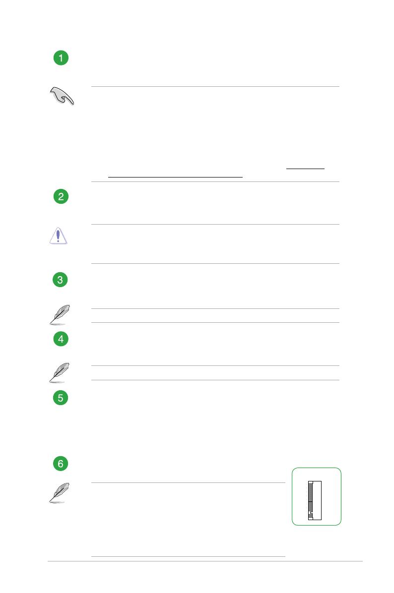
Digital audio connector (4-1 pin SPDIF_OUT)
ConnecttheS/PDIFOutmodulecabletothis
connector,theninstallthemoduletoaslotopeningat
thebackofthesystemchassis.
Front panel audio connector (10-1 pin AAFP)
Thisconnectorisforachassis-mountedfrontpanelaudioI/Omodulethatsupports
eitherHDAudioorlegacyAC`97audiostandard.Connectoneendofthefront
panelaudioI/Omodulecabletothisconnector.
• Werecommendthatyouconnectahigh-denitionfrontpanelaudiomoduletothis
connectortoavailofthemotherboard’shigh-denitionaudiocapability.
• Ifyouwanttoconnectahigh-denitionfrontpanelaudiomoduletothisconnector,
settheFrontPanelTypeitemintheBIOSsetupto[HDAudio].Ifyouwantto
connectanAC’97frontpanelaudiomoduletothisconnector,settheitemto
[AC97].Bydefault,thisconnectorissetto[HDAudio].
PCI Express 3.0/2.0 x1 slots
ThismotherboardsupportsPCIExpress3.0/2.0x1networkcards,SCSIcards,and
othercardsthatcomplywiththePCIExpressspecications
PCI Express 3.0/2.0 x16 slot
ThismotherboardhasaPCIExpress3.0/2.0x16slotthatsupportsPCIExpress
3.0/2.0x16graphiccardscomplyingwiththePCIExpressspecications.
SPDIF_OUT
+5V
SPDIFOUT
GND
PIN 1
LPT connector (26-1 pin LPT)
TheLPT(LinePrintingTerminal)connectorsupportsdevicessuchasaprinter.
LPTstandardizesasIEEE1284,whichistheparallelportinterfaceonIBMPC-
compatiblecomputers.
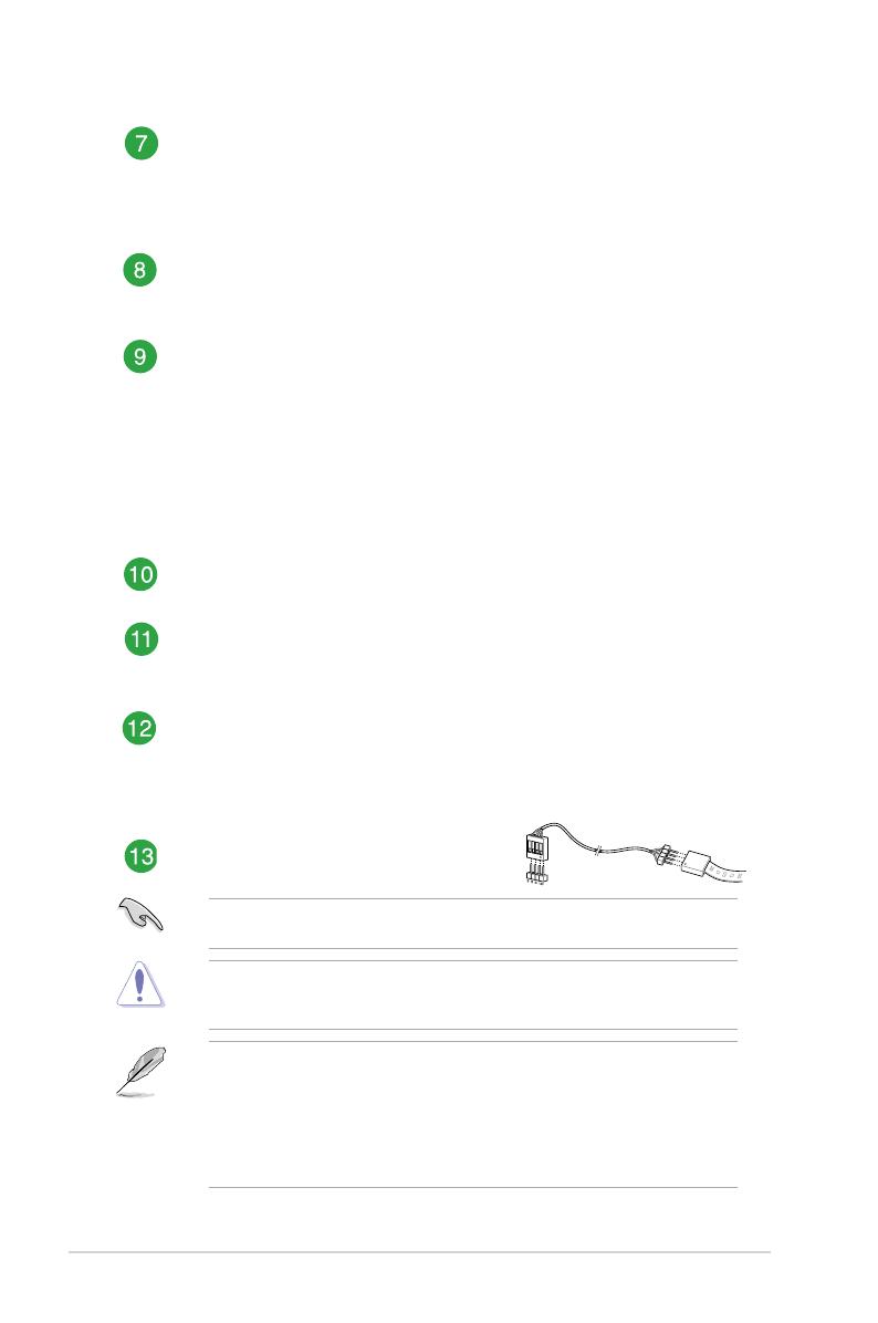
Clear RTC RAM (2-pin CLRTC)
ThisheaderallowsyoutocleartheCMOSRTCRAMdataofthesystemsetup
informationsuchasdate,time,andsystempasswords.
To erase the RTC RAM:
1. TurnOFFthecomputerandunplugthepowercord.
2. Useametalobjectsuchasascrewdrivertoshortthetwopins.
3. PlugthepowercordandturnONthecomputer.
4. Holddownthe<Del>keyduringthebootprocessandenterBIOSsetup
tore-enterdata.
Ifthestepsabovedonothelp,removetheonboardbatteryandshortthetwopins
againtocleartheCMOSRTCRAMdata.AfterclearingtheCMOS,reinstallthe
battery.
CLRTC
+3V_BAT
GND
PIN 1
ASUS PRIME B360M-A
1-5
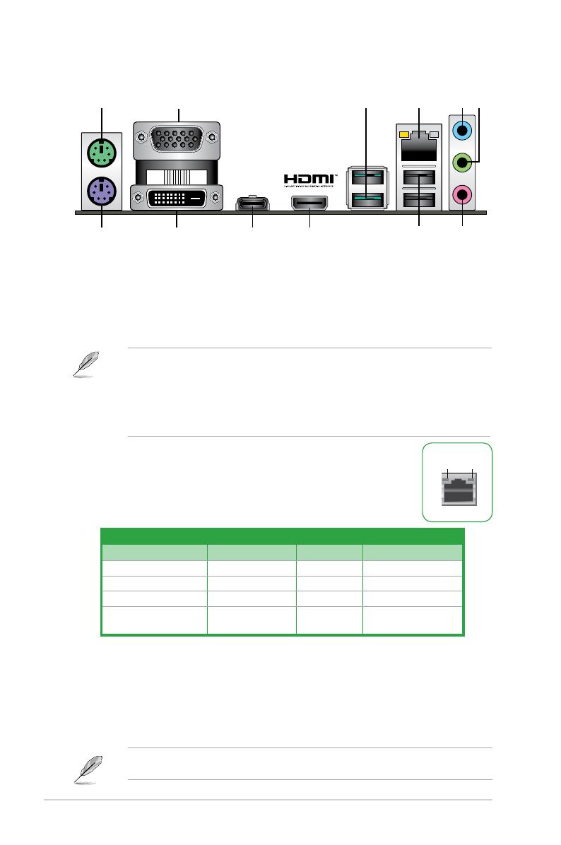
1. PS/2 mouse port (green).ThisportisforaPS/2mouse.
2. Video Graphics Adapter (VGA) port.This15-pinportisforaVGAmonitororother
VGA-compatibledevices.
3. USB 3.1 Gen 2 (up to 10Gbps) ports (teal blue, Type A).These9-pinUniversal
SerialBus3.1(USB3.1)Gen2portsareforUSB3.1Gen2devices.
• USB3.1Gen2/Gen1devicescanonlybeusedfordatastorage.
• DuetothedesignoftheIntel
®
300serieschipset,allUSBdevicesconnectedtothe
USB2.0andUSB3.1Gen2/Gen1portsarecontrolledbythexHCIcontroller.
SomelegacyUSBdevicesmustupdatetheirrmwareforbettercompatibility.
• WestronglyrecommendthatyouconnectUSB3.1Gen2devicestoUSB3.1Gen2
portsforfasterandbetterperformancefromyourUSB3.1Gen2devices.
4. LAN (RJ-45) port.ThisportallowsGigabitconnectiontoaLocal
AreaNetwork(LAN)throughanetworkhub.
Rear panel connectors
1 3 4
812
10 9
5 6
7
2
11
5. Line In port (light blue).Thisportconnectstothetape,CD,DVDplayer,orother
audiosources.
6. Line Out port (lime).Thisportconnectstoaheadphoneoraspeaker.Inthe4.1,5.1
and7.1-channelcongurations,thefunctionofthisportbecomesFrontSpeakerOut.
7. Microphone port (pink).Thisportconnectstoamicrophone.
Refertotheaudiocongurationtableforthefunctionoftheaudioportsin2.1,4.1,5.1,or
7.1-channelconguration.
Activity/Link LED Speed LED
Status Description Status
Description
Off Nolink OFF 10Mbpsconnection
Orange Linked ORANGE 100Mbpsconnection
Orange(Blinking) Dataactivity GREEN 1Gbpsconnection
Orange(Blinkingthen
steady)
Readytowakeup
fromS5mode
_ _
LAN port
Speed
LED
Activity Link
LED
LAN port LED indications

1-6
Chapter 1: Product introduction
Audio 2.1, 4.1, 5.1, or 7.1-channel configuration
Port
Headset
2.1-channel
4.1-channel 5.1-channel
7.1-channel
LightBlue(Rearpanel) LineIn RearSpeakerOut RearSpeakerOut RearSpeakerOut
Lime(Rearpanel) LineOut FrontSpeakerOut FrontSpeakerOut FrontSpeakerOut
Pink(Rearpanel) MicIn MicIn Bass/Center Bass/Center
Lime(Frontpanel) - - - SideSpeakerOut
To configure a 7.1-channel audio output:
UseachassiswithHDaudiomoduleinthefrontpaneltosupporta7.1-channelaudio
output.
8. USB 2.0 ports.These4-pinUniversalSerialBus(USB)portsareforUSB2.0/1.1
devices.
9. HDMI port. ThisportisforaHigh-DenitionMultimediaInterface(HDMI)connector,
andisHDCPcompliantallowingplaybackofHDDVD,Blu-Ray,andotherprotected
content.
10. USB 5Gb/s Type C port.This24-pinUniversalSerialBus(USB)portisforUSB(Type
C)devices.
11. DVI-D port.ThisportisforanyDVI-Dcompatibledevice.
DVI-DcannotbeconvertedtooutputfromRGBSignaltoCRTandisnotcompatiblewith
DVI-I.
12. PS/2 keyboard port (purple).ThisportisforaPS/2keyboard.

ASUS PRIME B360M-A
1-7
Central Processing Unit (CPU)
ThismotherboardcomeswithasurfacemountLGA1151socket
designedforthe8
th
GenerationIntel
®
Core™i7/Core™i5/Core™i3,
Pentium
®
andCeleron
®
processors.
• EnsurethatyouinstallthecorrectCPUdesignedfortheLGA1151socketonly.DO
NOTinstallaCPUdesignedforLGA1150,LGA1155andLGA1156socketsonthe
LGA1151socket.
• Uponpurchaseofthemotherboard,ensurethatthePnPcapisonthesocketand
thesocketcontactsarenotbent.ContactyourretailerimmediatelyifthePnPcap
ismissing,orifyouseeanydamagetothePnPcap/socketcontacts/motherboard
components.
• Keepthecapafterinstallingthemotherboard.ASUSwillprocessReturnMerchandise
Authorization(RMA)requestsonlyifthemotherboardcomeswiththecaponthe
LGA1151socket.
• Theproductwarrantydoesnotcoverdamagetothesocketcontactsresultingfrom
incorrectCPUinstallation/removal,ormisplacement/loss/incorrectremovalofthePnP
cap.
Installing the CPU
1
4
UnplugallpowercablesbeforeinstallingtheCPU.
ApplytheThermalInterfaceMaterialtotheCPUheatsinkandCPUbeforeyouinstallthe
heatsinkandfanifnecessary.
2
3
A
B
A
B
C
D
5
4
4
5

1-8
Chapter 1: Product introduction
System memory
Overview
ThismotherboardcomeswithfourDoubleDataRate4(DDR4)DualInlineMemoryModule
(DIMM)sockets.ThegureillustratesthelocationoftheDDR4DIMMsockets:
Channel Sockets
ChannelA DIMM_A1&DIMM_A2*
ChannelB DIMM_B1&DIMM_B2*
• YoumayinstallvaryingmemorysizesinChannelAandChannelB.Thesystem
mapsthetotalsizeofthelower-sizedchannelforthedual-channelconguration.Any
excessmemoryfromthehigher-sizedchannelisthenmappedforsingle-channel
operation.
• AlwaysinstalltheDIMMSwiththesameCASLatency.Foranoptimumcompatibility,
werecommendthatyouinstallmemorymodulesofthesameversionordatacode
(D/C)fromthesamevendor.Checkwiththevendortogetthecorrectmemory
modules.
• DDR42666MHzandhighermemorymoduleswillrunatmax.2666MHzonIntel
®
8th
Generation6-coreorhigherprocessors.
• Memorymoduleswithmemoryfrequencyhigherthan2133MHzanditscorresponding
timingortheloadedX.M.P.ProleisnottheJEDECmemorystandard.Thestability
andcompatibilityofthesememorymodulesdependontheCPU’scapabilitiesand
otherinstalleddevices.
• ThedefaultmemoryoperationfrequencyisdependentonitsSerialPresenceDetect
(SPD),whichisthestandardwayofaccessinginformationfromamemorymodule.
Underthedefaultstate,somememorymodulesforoverclockingmayoperateata
lowerfrequencythanthevendor-markedvalue.
• Forsystemstability,useamoreefcientmemorycoolingsystemtosupportafull
memoryload(4DIMMs).
• Refertowww.asus.comforthelatestMemoryQVL(QualiedVendorsList)
DIMM_A1
DIMM_A2*
DIMM_B1
DIMM_B2*
ASUS PRIME B360M-A
1-9
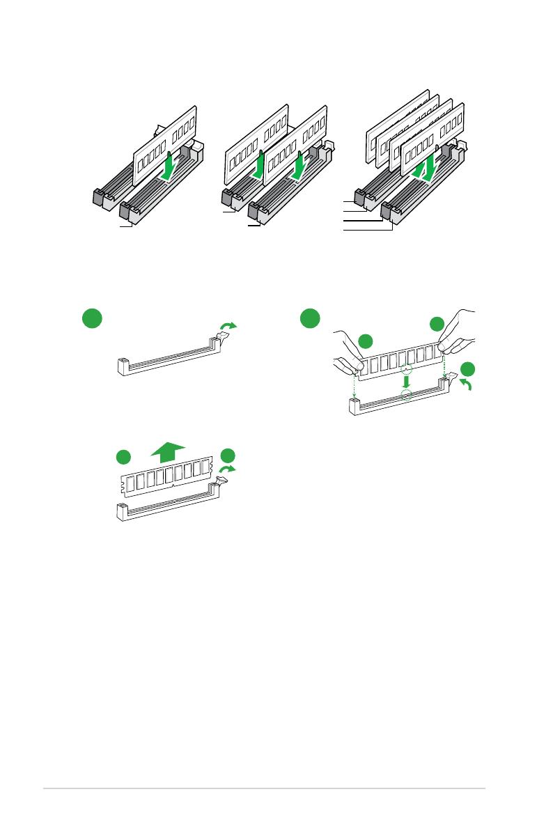
Installing a DIMM
1 2
To remove a DIMM
B
A
B
A
A
Recommended memory configurations
DIMM_A2*
DIMM_B1
DIMM_B2*
DIMM_A2*
DIMM_B2*
DIMM_A1
DIMM_A2*
BIOS information
2
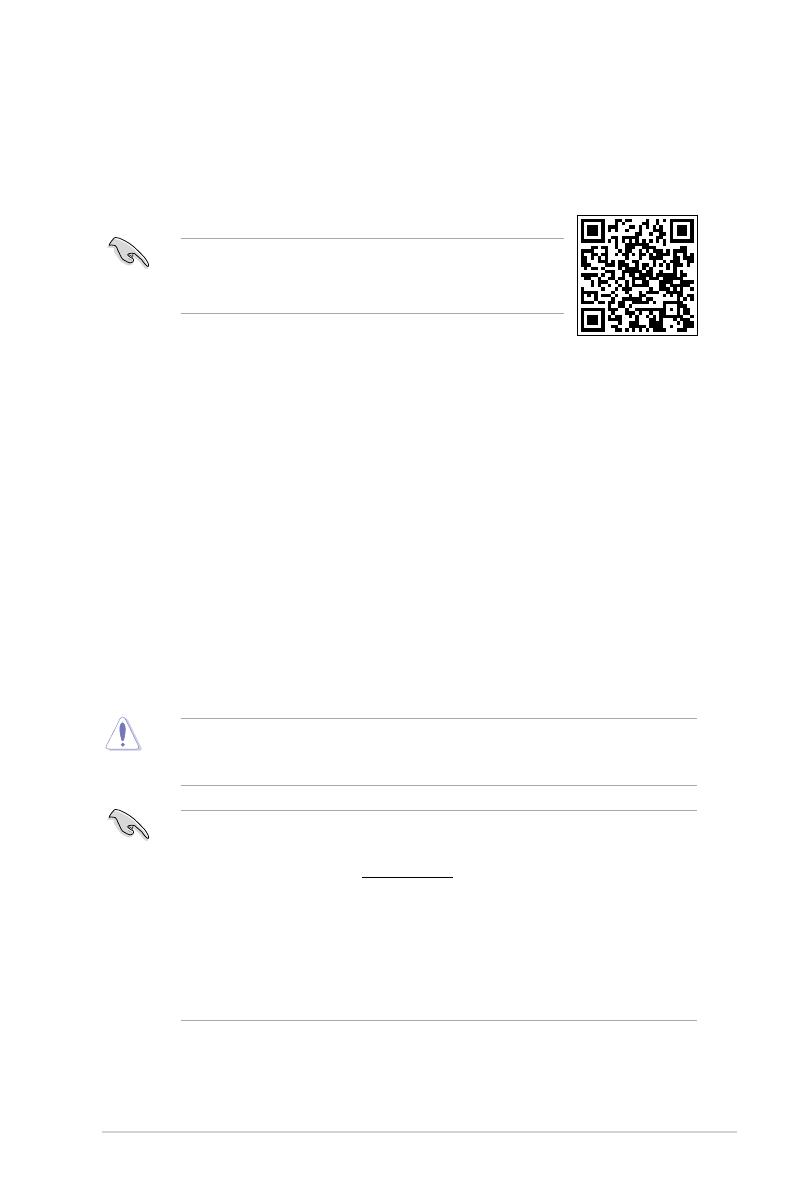
• ScantheQRcodetoviewtheBIOSupdateguide.
• BeforeusingtheASUSCrashFreeBIOS3utility,renamethe
BIOSleintheremovabledeviceintoPB360MA.CAP.
BIOS setup program
UsetheBIOSSetupprogramtoupdatetheBIOSorcongureitsparameters.TheBIOS
screensincludenavigationkeysandbriefonlinehelptoguideyouinusingtheBIOSSetup
program.
Entering BIOS Setup at startup
To enter BIOS Setup at startup:
Press<Delete>or<F2>duringthePower-OnSelfTest(POST).Ifyoudonotpress<Delete>
or<F2>,POSTcontinueswithitsroutines.
Entering BIOS Setup after POST
To enter BIOS Setup after POST:
• Press<Ctrl>+<Alt>+<Del>simultaneously.
• Presstheresetbuttononthesystemchassis.
• Pressthepowerbuttontoturnthesystemoffthenbackon.Dothisoptiononlyifyou
failedtoenterBIOSSetupusingthersttwooptions.
Usingthepowerbutton,resetbutton,orthe<Ctrl>+<Alt>+<Del>keystoforceresetfroma
runningoperatingsystemcancausedamagetoyourdataorsystem.Werecommendyou
alwaysshutdownthesystemproperlyfromtheoperatingsystem.
• TheBIOSsetupscreensshowninthissectionareforreferencepurposesonly,and
maynotexactlymatchwhatyouseeonyourscreen.
• VisittheASUSwebsiteatwww.asus.comtodownloadthelatestBIOSleforthis
motherboard.
• IfthesystembecomesunstableafterchanginganyBIOSsetting,loadthedefault
settingstoensuresystemcompatibilityandstability.SelecttheLoad Optimized
DefaultsitemundertheExitmenuorpresshotkeyF5.
• IfthesystemfailstobootafterchanginganyBIOSsetting,trytocleartheCMOSand
resetthemotherboardtothedefaultvalue.SeesectionMotherboard overviewfor
informationonhowtoerasetheRTCRAM.
BIOS menu screen
TheBIOSsetupprogramcanbeusedundertwomodes:EZ ModeandAdvanced Mode.
Press<F7>tochangebetweenthetwomodes.
ASUS PRIME B360M-A
2-1
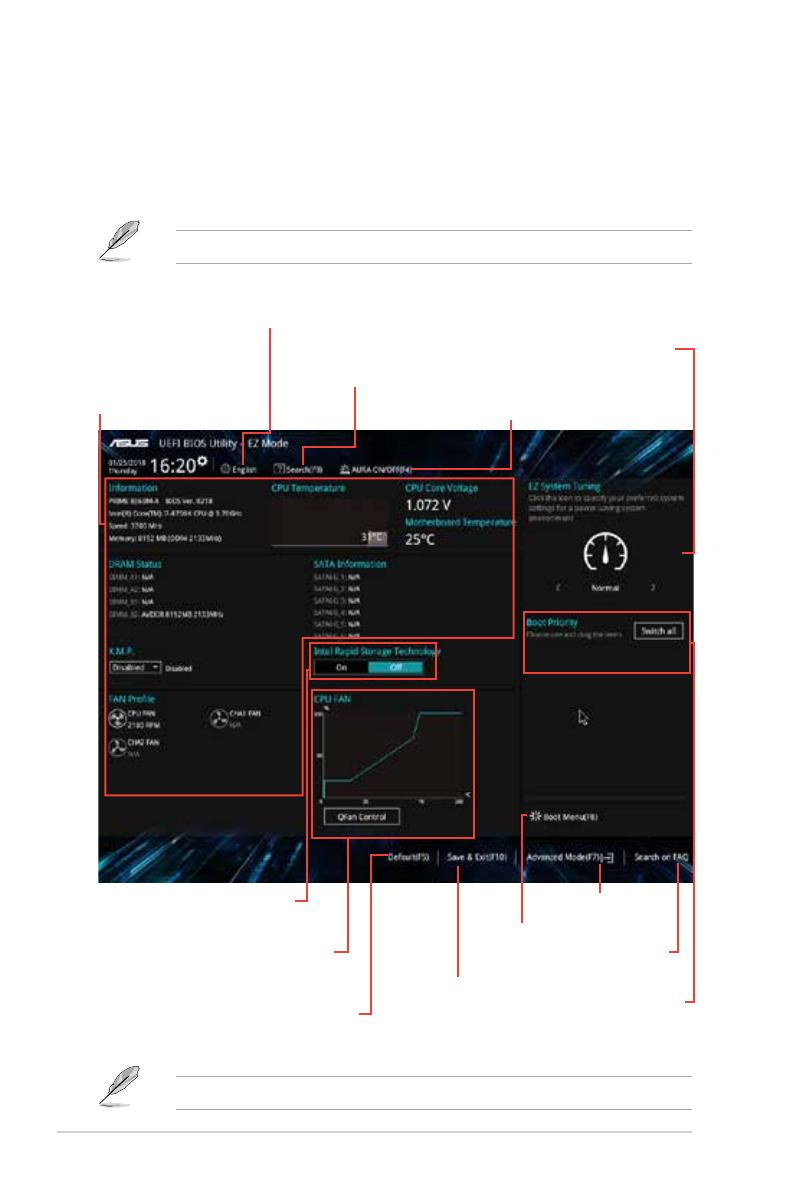
EZ Mode
Bydefault,theEZModescreenappearswhenyouentertheBIOSsetupprogram.TheEZ
Modeprovidesyouanoverviewofthebasicsysteminformation,andallowsyoutoselectthe
displaylanguage,systemperformancemode,fanproleandbootdevicepriority.Toaccess
theAdvancedMode,clickAdvanced Mode(F7)orpress<F7>.
ThedefaultscreenforenteringtheBIOSsetupprogramcanbechanged.
Thebootdeviceoptionsvarydependingonthedevicesyouinstalledtothesystem.
Saves the changes
and resets the system
Selects the display language of
the BIOS setup program
Displays the CPU/
motherboard
temperature, CPU
voltage output,
CPU/chassis fan
speed, and SATA
information
Displays the system
properties of the selected
mode. Click <Enter> to switch
EZ System Tuning modes
Displays the Advanced
mode menus
Selects the boot
device priority
Loads optimized
default settings
Shows the
bootable devices
Displays the CPU Fan’s speed
Click the button to manually
tune the fans
Search on
FAQs
Enables or disables the Intel
Rapid Storage Technology
Searches by BIOS item
name, enter the item name
to find the related item
listing
Turns the RGB LED ON/OFF
2-2
Chapter 2: BIOS information
/