Pioneer SPH-10BT User manual

Category
Microphones
Type
User manual
English Français Italiano Español Deutsch Nederlands Русский
SMARTPHONE RECEIVER
STATION D'ACCUEIL SMARTPHONE
SMARTPHONE RECEIVER
RECEPTOR PARA SMARTPHONE
SMARTPHONE-EMPFÄNGER
SMARTPHONE ONTVANGER
СМАРТ-РЕСИВЕР
SPH-10BT
Installation Manual
Manuel d'installation
Manuale d'installazione
Manual de instalacion
Installationsanleitung
Installatiehandleiding
Руководство по установке
2En
Important
When installing this unit in a vehicle
without an ACC (accessory) position on
the ignition switch, failure to connect the
red cable to the terminal that detects
operation of the ignition key may result
in battery drain.
Use of this unit in conditions other than
the following could result in fire or
malfunction.
Vehicles with a 12-volt battery and
neg
ative grounding.
When speaker output is used by 4
chan
nels, use speakers over 50 W
(maximum input power) and between 4
Ω to 8 Ω (impedance value). Do not use
1 Ω to 3 Ω speakers for this unit.
When rear speaker output is used by 2
Ω
of subwoofer, use speakers over 70 W
(maximum input power).
* Please refer to connections for a
co
nnection method.
T
o prevent a short-circuit, overheating or
malfunction, be sure to follow the
directions below.
Disconnect the negative terminal of the
bat
tery before installation.
Secure the wiring with cable clamps or
ad
hesive tape. Wrap adhesive tape
around wiring that comes into contact
with metal parts to protect the wiring.
– Place all cables away from moving parts,
su
ch as the shift lever and seat rails.
Place all cables away from hot places,
such
as near the heater outlet.
Do not connect the yellow cable to the
bat
tery by passing it through the hole
to the engine compartment.
Cover any disconnected cable
co
nnectors with insulating tape.
Do not shorten any cables.
Never cut the insulation of the power
cable
of this unit in order to share the
power with other devices. The current
capacity of the cable is limited.
Use a fuse of the rating prescribed.
Never wire the negative speaker cable
di
rectly to ground.
Never band together negative cables of
m
ultiple speakers.
When t
his unit is on, control signals are
sent through the blue/white cable.
Connect this cable to the system remote
control of an external power amp or the
vehicle’s auto-antenna relay control
terminal (max. 300 mA 12 V DC). If the
vehicle is equipped with a glass antenna,
connect it to the antenna booster power
supply terminal.
N
ever connect the blue/white cable to
the power terminal of an external power
amp. Also, never connect it to the power
terminal of the auto antenna. Doing so
may result in battery drain or a
malfunction.
T
he black cable is ground. Ground cables
for this unit and other equipment
(especially, high-current products such as
power amps) must be wired separately. If
they are not, an accidental detachment
may result in a fire or malfunction.
Th
e graphical symbol placed on
the product means direct current.
Connections/Installation
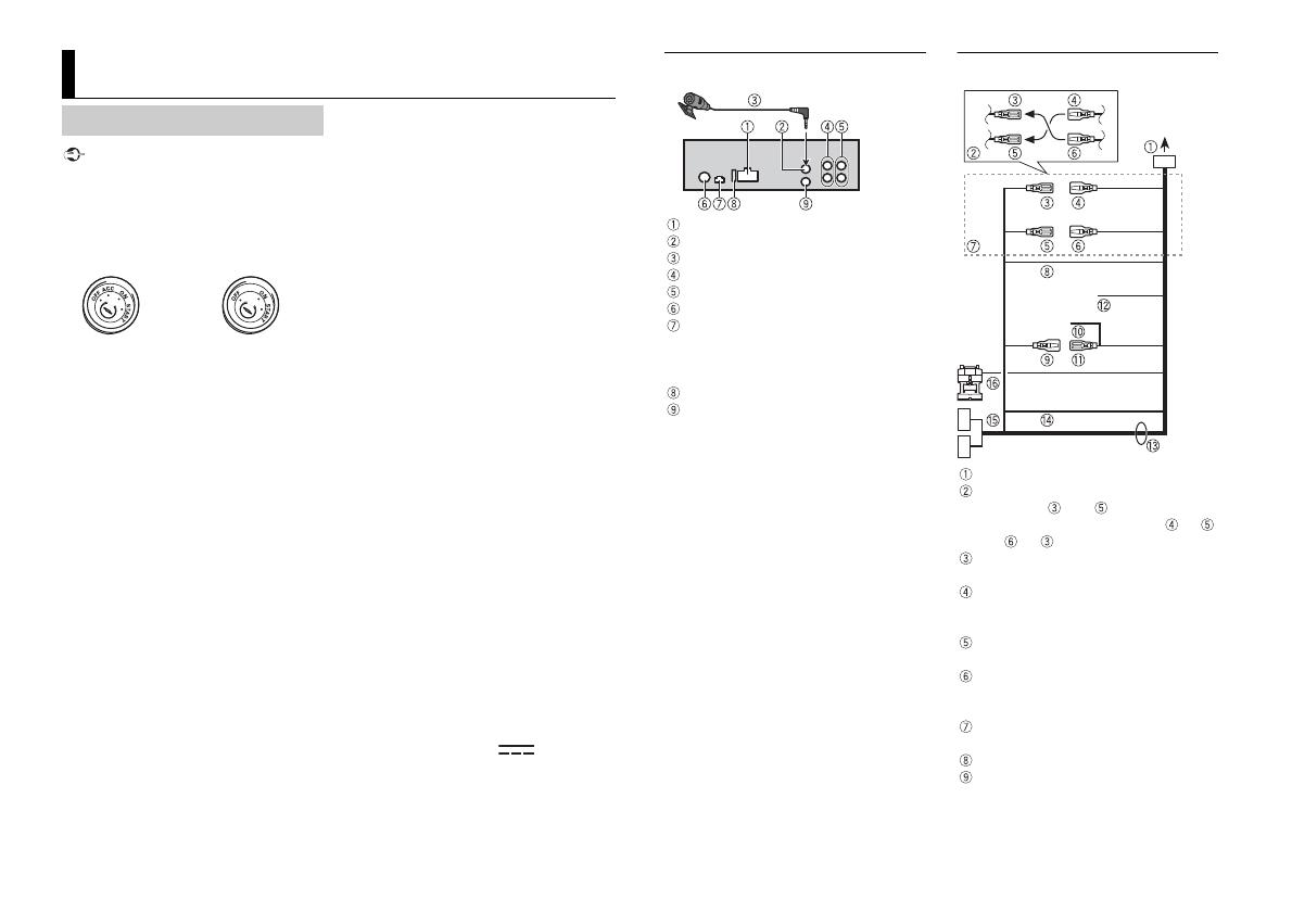
Connections
ACC position No ACC position
This unit
Power cord input
Microphone input
Microphone (3 m)
Rear output or subwoofer output
Front output
Antenna input
Parking sensor input
UART adaptor (supplied with parking
sen
sor unit (ND-PS1)) can be connected
(sold separately).
Fuse (10 A)
Wired remote input
Hard-wired remote control adapter can
be connec
ted (sold separately).
Power cord
To power cord input
Depending on the kind of vehicle, the
function of and may be different.
In this case, be sure to connect to
and to .
Yel low
Back-up (or accessory)
Yel low
Connect to the constant 12 V supply
te
rminal.
Red
Accessory (or back-up)
Red
Connect to terminal controlled by the
igni
tion switch (12 V DC).
Connect leads of the same colour to
each other.
Black (chassis ground)
Blue/white
The pin position of the ISO connector
wi
ll differ depending on the type of
3En
English
vehicle. Connect and when Pin 5
is an antenna control type. In another
t
ype of vehicle, never connect and
.
Blue/white
Connect to the system control terminal
of
the power amp (max. 300 mA 12 V
DC).
Blue/white
Connect to the auto-antenna relay
c
ontrol terminal (max. 300 mA 12 V DC).
Violet/white
Of the two lead wires connected to the
back
lamp, connect the one in which
the voltage changes when the gear shift
is in the REVERSE (R) position. This
connection enables the unit to sense
whether the car is moving forwards or
backwards.
Speaker leads
White: Front left
White/black: Front left
Gray: Front right
Gray/black: Front right
Green: Rear left
Green/black: Rear left
Violet: Rear right
Violet/black: Rear right
Orange/white
Connect to a cars illumination signal.
ISO connector
In some vehicles, the ISO connector
ma
y be divided into two. In this case, be
sure to connect to both connectors.
Light green
Used to detect the On/Off status of the
par
king brake. This lead must be
connected to the power supply side of
the parking brake switch.
NOTES
Change the initial menu of this unit. Refer
to [REAR-SP] in the INITIAL settings. The
subwoofer output of this unit is
monaural.
When using a subwoofer of 2 Ω, be sure
to connect the subwoofer to the violet
and violet/black leads of this unit. Do not
connect anything to the green and
green/black leads.
Power amp (sold separately)
Perform these connections when using the
optional amplifier.
System remote control
Connect to blue/white cable.
Power amp (sold separately)
Connect with RCA cables (sold
separately)
To front output
Front speaker
To rear output or subwoofer output
Rear speaker or subwoofer
Important
Check all connections and systems before
final installation.
Do not use unauthorized parts as this
may cause malfunctions.
C
onsult your dealer if installation requires
drilling of holes or other modifications to
the vehicle.
Do
not install this unit where:
it may interfere with operation of the
vehicl
e.
it may cause injury to a passenger as a
r
esult of a sudden stop.
I
nstall this unit away from hot places such
as near the heater outlet.
Installation
Optimum performance is
obtained when the unit is
installed at an angle of less
than 45°.
When installing, to ensure proper heat
dispersal when using this unit, make sure
you leave ample space behind the rear
panel and wrap any loose cables so they
are not blocking the vents.
DIN mount installation
1 Insert the supplied mounting sleeve
into the dashboard.
2 Secure the mounting sleeve by using a
screwdriver to bend the metal tabs
(90°) into place.
Dashboard
Mounting sleeve
Mak
e sure that the unit is installed
securely in place. An unstable
installation may cause skipping or
other malfunctions.
When not using the supplied
mounting sleeve
1 Determine the appropriate position
where the holes on the bracket and
the side of the unit match.
2 Tighten two screws on each side.
Tapping screw (5 mm × 9 mm, not
supplied with product)
Mounting bracket
Dashboard or console
Removing the unit (installed with
the supplied mounting sleeve)
1 Remove the trim ring.
Trim ring
Rel
easing the front panel allows easier
access to the trim ring.
When reat
taching the trim ring, point
the side with the dent part up.
2 Insert the supplied extraction keys
into both sides of the unit until they
click into place.
3 Pull the unit out of the dashboard.
Leave ample
space
5 cm
5 cm
4En
The microphone should be placed directly
in front of the driver at a suitable distance
to pick up their voice clearly.
CAUTION
It is extremely dangerous to allow the
microphone lead to become wound
around the steering column or shift lever.
Be sure to install the microphone in such a
way that it will not obstruct driving. It is
recommended to use the clamps (sold
separately) to arrange the lead.
NOTE
Depending on the vehicle model, the
microphone cable length may be too short
when you mount the microphone on the
sun visor. In such cases, install the
microphone on the steering column.
To install on the sun visor
1 Fit the microphone lead into the
groove.
2 Install the microphone clip on the sun
visor.
Lowering the sun visor reduces the
v
oice recognition rate.
To install on the steering
column
1 Slide the microphone base to detach it
from the microphone clip.
Microphone
Microphone clip
Microphone base
2 Install the microphone on the rear side
of the steering column.
Installing the microphone
Microphone
lead
Groove
Microphone clip
Double-sided tape
5En
English
5Fr
Fraais
5It
Italiano
5Es
Español
5De
Deutsch
5Nl
Nederlands
5Ru
Русский
7Ru
Русский
© 2018 PIONEER CORPORATION. All rights reserved.
© 2018 PIONEER CORPORATION. Tous droits de reproduction et de traduction réservés.
© PIONEER CORPORATION, 2018. Все права защищены.
<CRD5084-A> EW
  • Page 1 1
  • Page 2 2
  • Page 3 3
  • Page 4 4
  • Page 5 5
  • Page 6 6
  • Page 7 7
  • Page 8 8
  • Page 9 9
  • Page 10 10
  • Page 11 11
  • Page 12 12
  • Page 13 13
  • Page 14 14
  • Page 15 15
  • Page 16 16
  • Page 17 17
  • Page 18 18
  • Page 19 19
  • Page 20 20
  • Page 21 21
  • Page 22 22
  • Page 23 23
  • Page 24 24
  • Page 25 25
  • Page 26 26
  • Page 27 27
  • Page 28 28
  • Page 29 29
  • Page 30 30
  • Page 31 31
  • Page 32 32

Pioneer SPH-10BT User manual

Category
Microphones
Type
User manual

Ask a question and I''ll find the answer in the document

Finding information in a document is now easier with AI