Broan ELITE RMIP33 User manual

Category
Cooker hoods
Type
User manual
MODELS RMIP33 AND RMIP45
INTENDED FOR DOMESTIC COOKING ONLY
INSTALLER: LEAVE THIS MANUAL WITH HOMEOWNER.
HOMEOWNER: USE AND CARE INFORMATION ON PAGES 12 AND 13.
Broan-NuTone LLC; Hartford, Wisconsin www.broan.com 800-558-1711
Broan-NuTone Canada; Mississauga, Ontario www.broan.ca 877-896-1119
REGISTER YOUR PRODUCT ON LINE AT: www.broan.com/register
SV05861 rev. I
HB0031
INSTALLATION INSTRUCTIONS
READ AND SAVE THESE INSTRUCTIONS
!
!
WARNING WARNING
- 2 -
TO REDUCE THE RISK OF FIRE, ELECTRIC
SHOCK OR INJURY TO PERSONS, OBSERVE
THE FOLLOWING:
1. Use this unit only in the manner intended by the
manufacturer. If you have questions, contact the
manufacturer at the address or telephone number
listed in the warranty.
2. Before servicing or cleaning unit, switch power off
at service panel and lock service disconnecting
means to prevent power from being switched on
accidentally. When the service disconnecting
means cannot be locked, securely fasten a prominent
warning device, such as a tag, to the service panel.
3. Installation work and electrical wiring must be done
by qualified personnel in accordance with all
applicable codes and standards, including fire-rated
construction codes and standards.
4. Sufficient air is needed for proper combustion and
exhausting of gases through the flue (chimney) of
fuel burning equipment to prevent backdrafting.
Follow the heating equipment manufacturer’s
guidelines and safety standards such as those
published by the National Fire Protection
Association (NFPA), and the American Society for
Heating, Refrigeration and Air Conditioning
Engineers (ASHRAE), and the local code authorities.
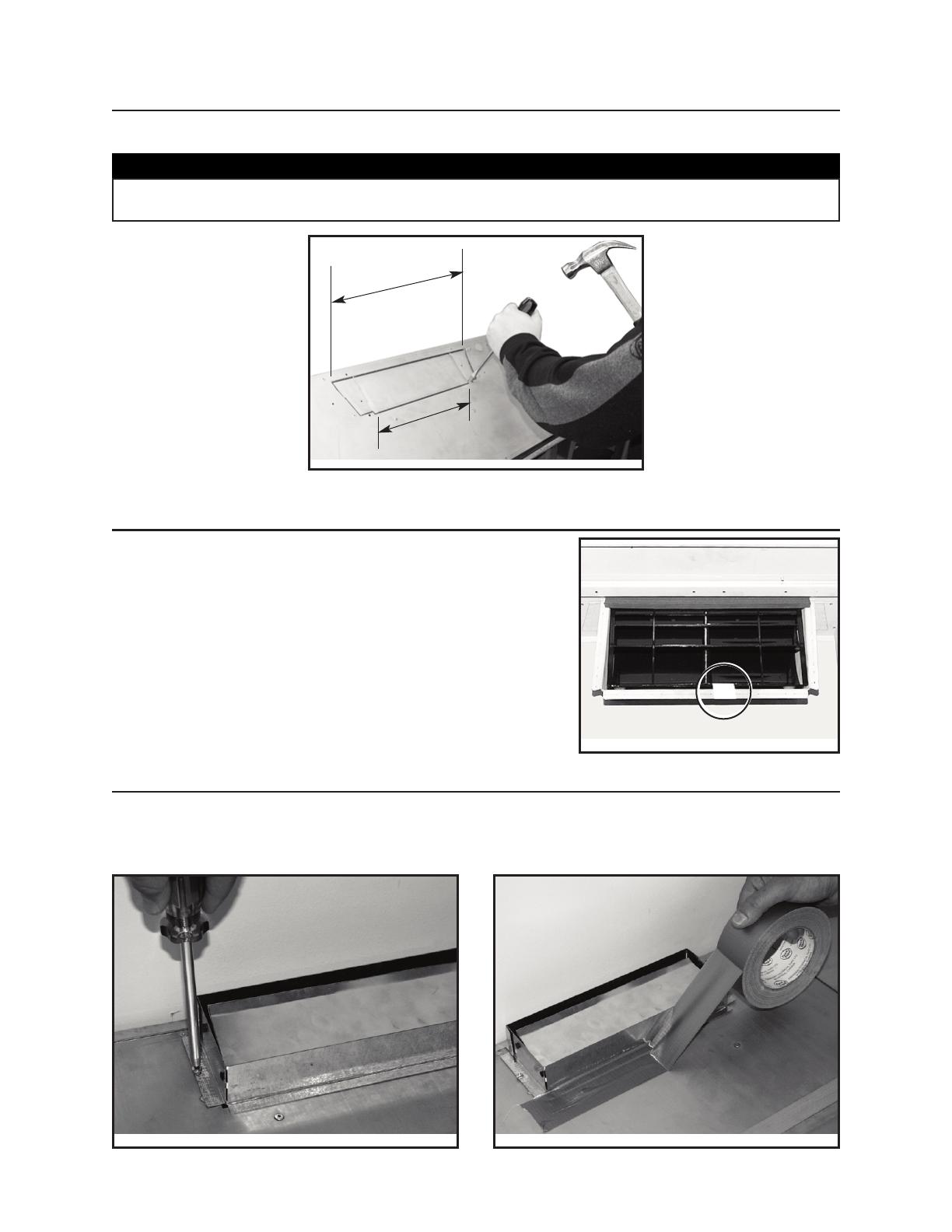
5. When cutting or drilling into wall or ceiling, do not
damage electrical wiring and other hidden utilities.
6. Ducted fans must always be vented to the
outdoors.
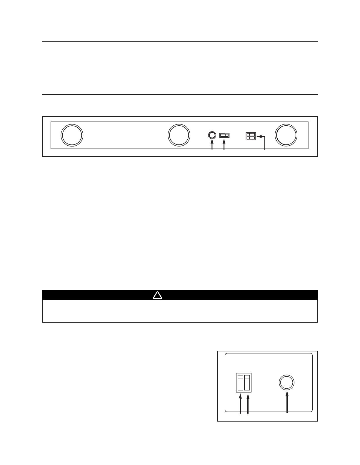
7. Do not use this unit with any solid-state speed
control device other than RMIPWC optional wall
mounted control.
8. To reduce the risk of fire, use only metal ductwork.
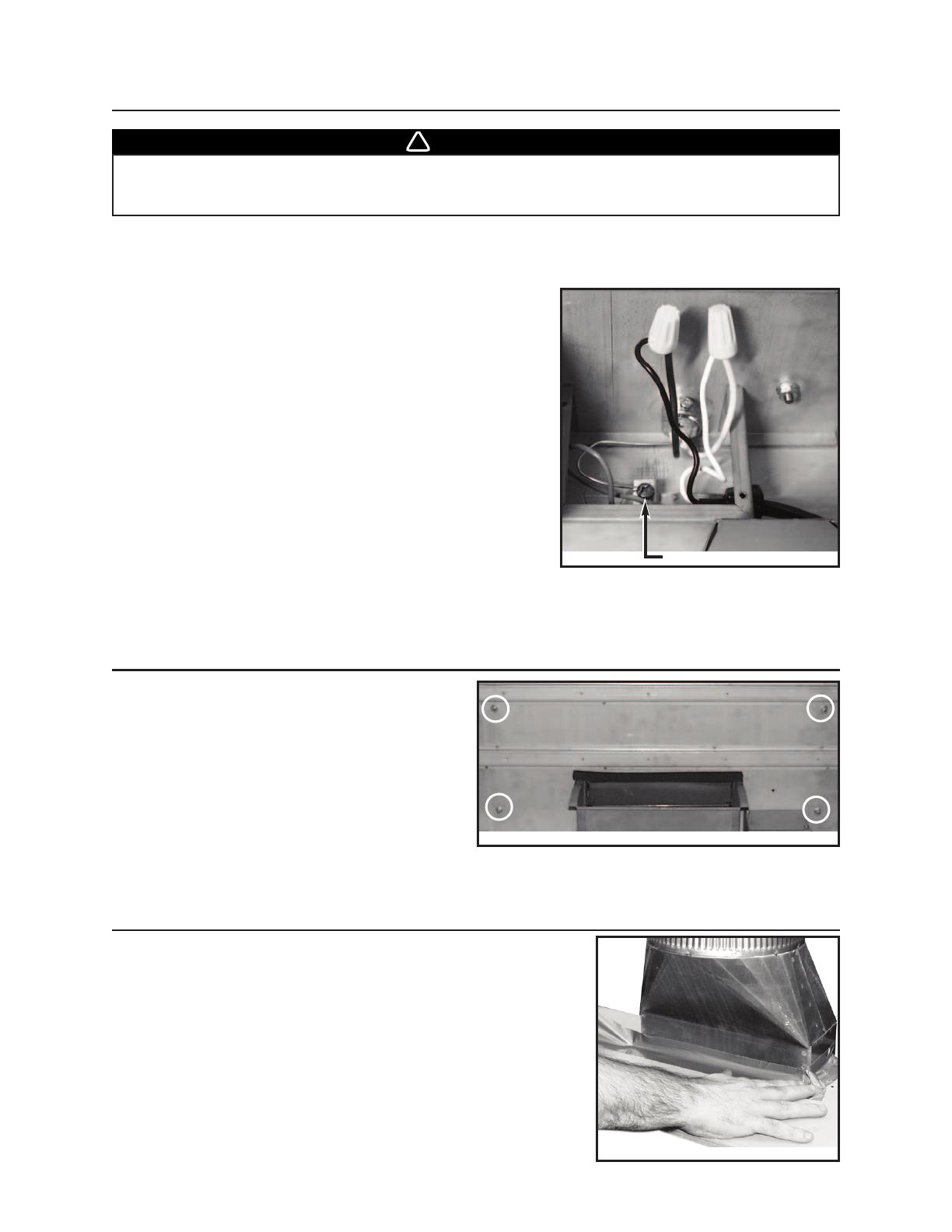
9. This unit must be grounded.
10.
When applicable local regulations comprise more
restrictive installation and/or certification
requirements, the aforementioned requirements
prevail on those of this document and the installer
agrees to conform to these at his own expenses.
TO REDUCE THE RISK OF A RANGE TOP
GREASE FIRE:
a) Never leave surface units unattended at high
settings. Boilovers cause smoking and greasy
spillovers that may ignite. Heat oils slowly on low or
medium settings.
b) Always turn hood ON when cooking at high heat or
when cooking flaming foods.
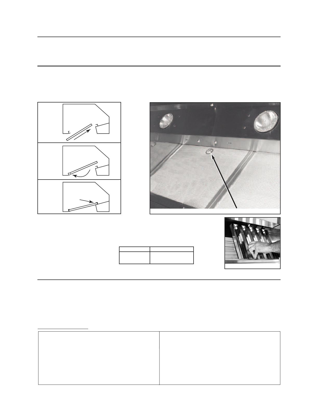
c) Clean ventilating fans frequently. Grease should
not be allowed to accumulate on fan or filter.
d) Use proper pan size. Always use cookware
appropriate for the size of the surface element.
TO REDUCE THE RISK OF INJURY TO PERSONS
IN THE EVENT OF A RANGE TOP GREASE
FIRE, OBSERVE THE FOLLOWING*:
1. SMOTHER FLAMES with a close-fitting lid,
cookie sheet or metal tray, then turn off the
burner. BE CAREFUL TO PREVENT BURNS. IF
THE FLAMES DO NOT GO OUT IMMEDIATELY,
EVACUATE AND CALL THE FIRE DEPARTMENT.
2. NEVER PICK UP A FLAMING PAN – You may
be burned.
3. DO NOT USE WATER, including wet dishcloths or
towels – This could cause a violent steam explosion.
4. Use an extinguisher ONLY if:
A. You own a Class ABC extinguisher and
you know how to operate it.
B. The fire is small and contained in the area
where it started.
C. The fire department has been called.
D. You can fight the fire with your back to an exit.
* Based on “Kitchen Fire Safety Tips” published by NFPA.
CAUTION
1. For indoor use only
2. For general ventilating use only. Do not use to
exhaust hazardous or explosive materials and vapors.
3. To avoid motor bearing damage and noisy and/or
unbalanced impellers, keep drywall spray,
construction dust, etc. off power unit.
4. Your insert motor has a thermal overload which will
automatically shut off the motor if it becomes
overheated. The motor will restart when it cools
down. If the motor continues to shut off and restart,
have the insert serviced.
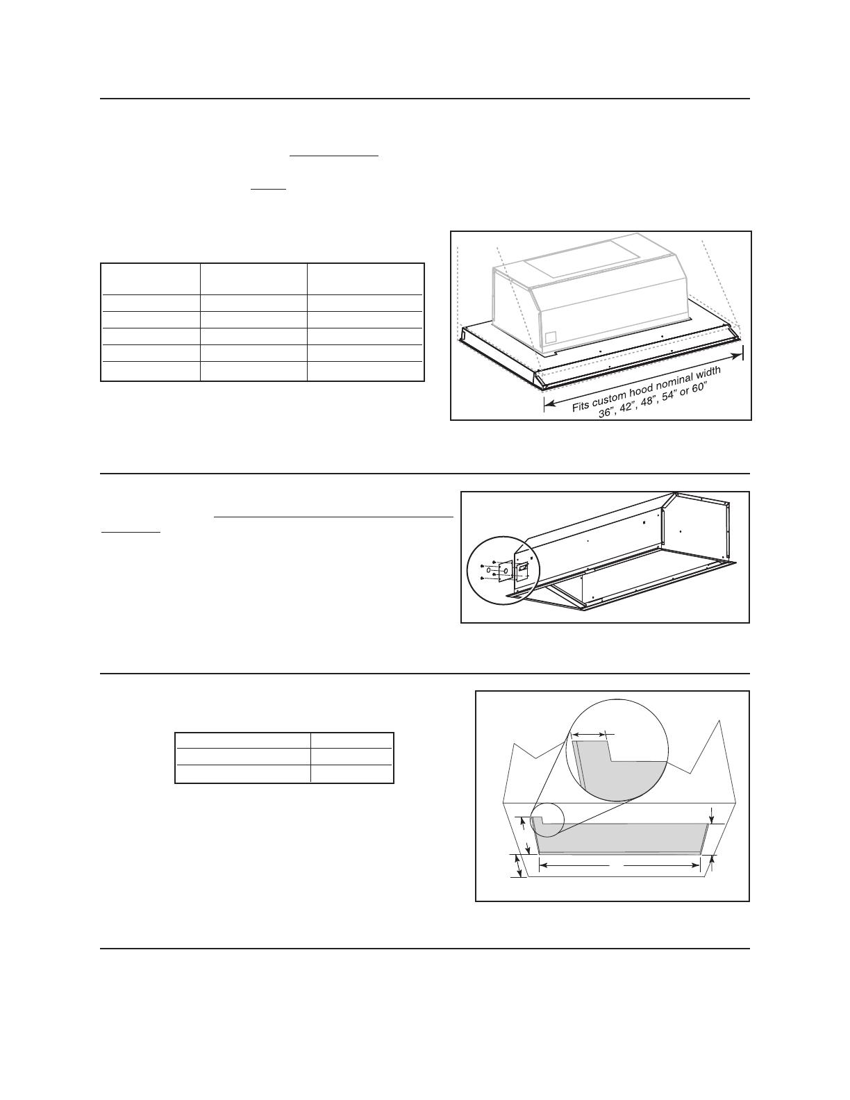
5. The minimum hood distance above cooktop must
not be less than 24”. A maximum of 30” above
cooktop is highly recommended for best capture of
cooking impurities.
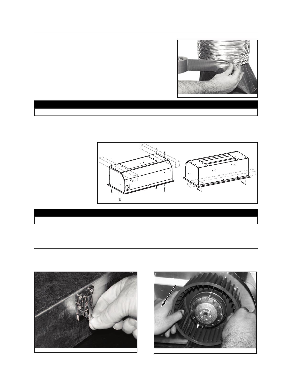
6. Two installers are recommended because of the
large size and weight of this unit.
7. To reduce the risk of fire and to properly exhaust
air, be sure to duct air outside – Do not exhaust air
into spaces within walls or ceiling or into attics,
crawl space or garage.
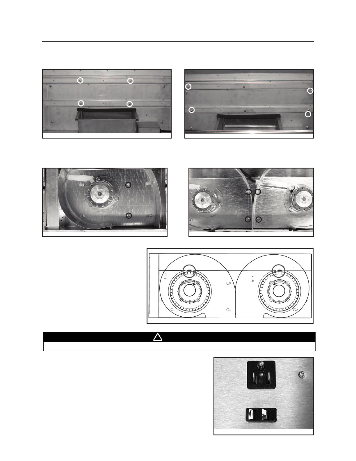
8. This product is equipped with a thermostat which
may start blower automatically. To reduce the risk
of injury and to prevent power from being switched
on accidentally, switch power off at service panel
and lock or tag service panel.
9. Because of the high exhausting capacity of this
unit, you should make sure enough air is entering
the house to replace exhausted air by opening a
window close to or in the kitchen.
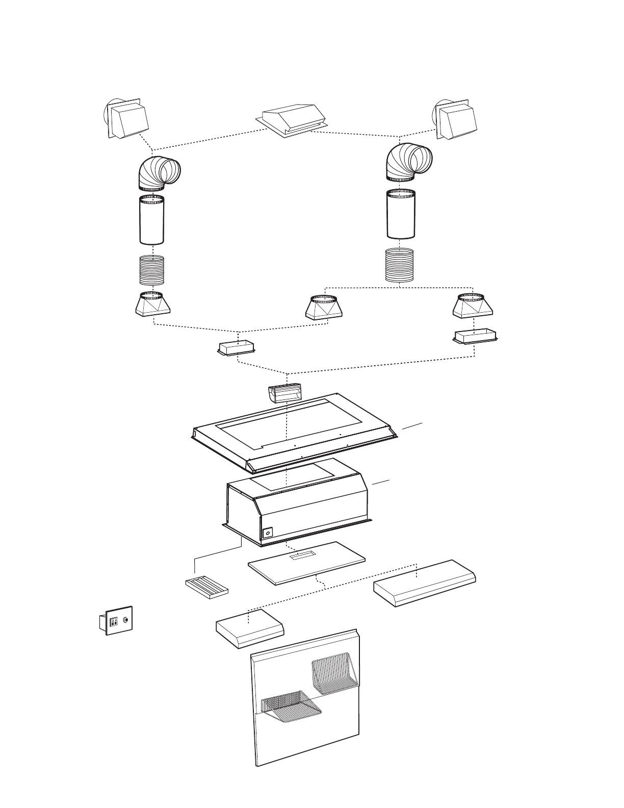
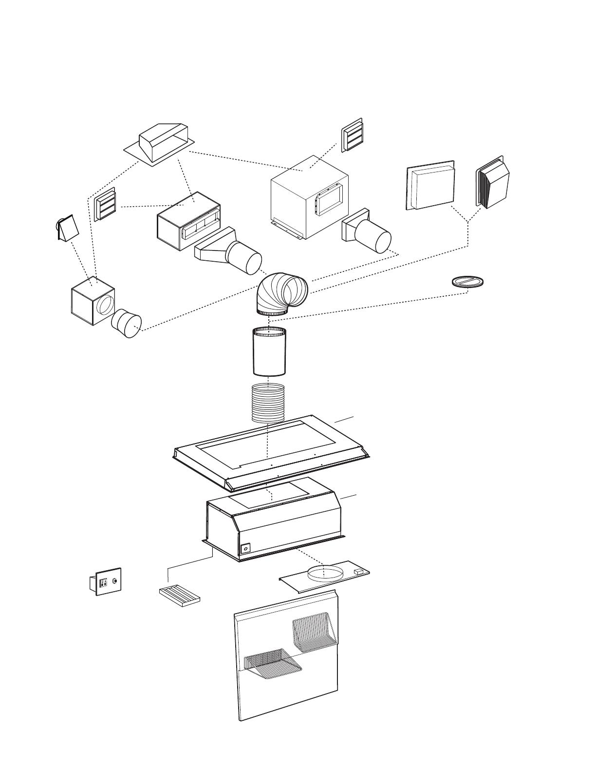
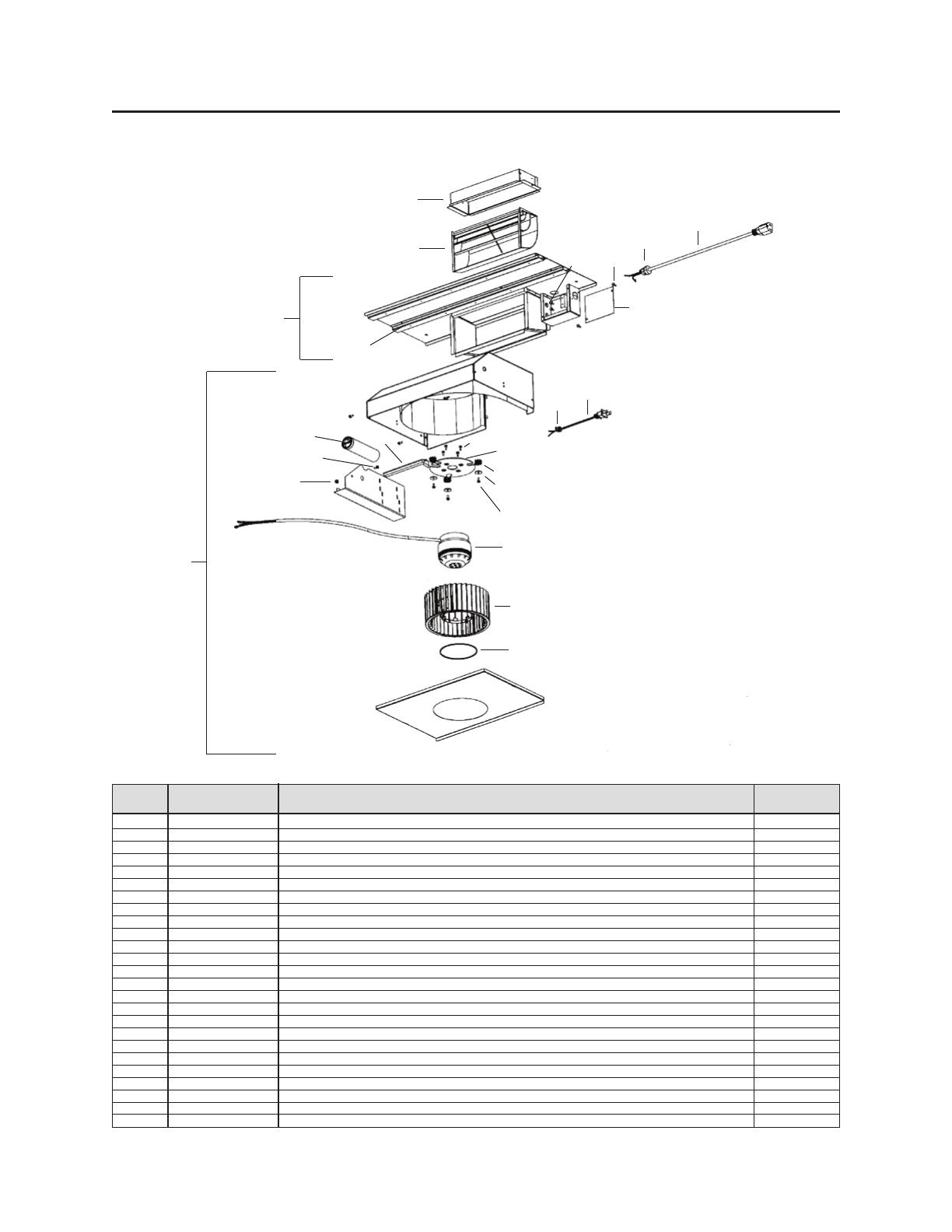
10. To reduce the risk of fire and electrical shock, the
Broan Elite models RMIP33 and RMIP45 must be
installed only with Broan interior blower models P5
or P8; Broan exterior models 331H, 332H, 335 or
336; Broan in-line blowers models HLB3, HLB6,
HLB9, HLB11. Other blowers cannot be substituted.
(Blowers sold separately).
11. Use with approved cord-connection kit only.
12. Please read specification label on product for
further information and requirements.
!
!
HL0067
- 3 -
RMP Series Backsplash
(Stainless Steel wall
covering with warming
shelves. Optional)
RML3336S, RML3342S,
RML4548S, RML4554S or
RML4560S
Custom Hood Liner (optional)
Model 415
7” Rd adjustable
elbow (optional)
8” Rd
adjustable
elbow (optional)
Model 412
transition
(3¼” x 10” to 7”)
Adapter and damper 3¼ x 10’
(supplied with P5 and P8 blowers)
Adapter and damper 3¼ x 14’
(supplied with P8 blower)
Model P5
single-blower
(500 cfm)
RMIP33
OR RMIP45
INSERT
- RMIP33 AND RMIP45 INSERT SYSTEM -
INTERIOR BLOWERS
Flow deviator
(supplied with
P5 and P8 blowers)
Model 647
(7” Rd wall cap)
Model 634 or 644
(roof cap)
Model 643
(8” Rd wall cap)
8” Rd
standard
duct
Model 407
(7” Rd x 24’
section)
7” Rd metal
flexible duct
(optional)
8” Rd metal
flexible duct
(optional)
Model 413
transition
(3¼” x 10” to 8”)
Model 459
transition
(3¼” x 14” to 8”)
Model P8
dual-blower (900 cfm)
NOTE : The dual blower P8 can be
installed either with 7’ round
or 8’ round ductwork.
For optimal air and quiet
sound performance, use 8’’
round ductwork.
Rough-in kit
(supplied with P5 and P8 blowers)
RMIPWC
Wall control
(Optional)
RBFIP Series
Baffle Filters
(Optional)
- 4 -
HL0068
RMP Series Backsplash
(Stainless Steel wall
covering with warming
shelves. Optional)
RML3336S, RML3342S,
RML4548S, RML4554S
or RML4560S
Custom Hood Liner (optional)
Model 418
10” Rd
adjustable elbow
(optional)
Model HLB3 (280 cfm)
in-line blower
(includes one 8” to 10”
round transition)
RMIP33
OR RMIP45
INSERT
- RMIP33 AND RMIP45 INSERT SYSTEM -
IN-LINE AND EXTERIOR BLOWERS
Model 331H (600 cfm)
or 332H (900 cfm)
exterior blower
Model 335 (1200 cfm)
or 336 (1500 cfm)
exterior blower
Model 441
(10” Rd
wall cap)
Model 437
(High capacity roof cap)
Model 441
(10” Rd wall cap)
Model 421
(10” Rd. vert.
in-line damper)
Recommended
for use with
exterior blowers
Model 410
(10” Rd duct
- 2ft. sections)
10” Rd metal
flexible duct
(optional)
332KR in-line and exterior blower
rough-in kit - Purchase separately.
RMIPWC
Wall control
(Optional)
RBFIP Series
Baffle filters
(Optional)
Model HLB6 (600 cfm)
in-line blower
(includes two 4½” x 18½”
to 10’ round transitions)
Model HLB9 (800 cfm)
or HLB11 (1100 cfm)
in-line blower
(includes two 8” x 12” to
10’ round transitions)
Model 643
(8” Round
wall cap)
- 5 -
1. SELECT BLOWER OPTION AND INSTALL DUCTWORK
Either an interior or exterior blower or in-line blower may be used with this insert. The insert model RMIP33 or RMIP45 must
be installed with blower models P5, P8, HLB3, HLB6, HLB9, HLB11, 331H, 332H, 335 or 336 only. Other blowers
cannot be substituted. (Blowers sold separately).
Plan where and how the ductwork will be installed. Access to the top of the hood is preferred for connection of ductwork.
As an alternative, flexible metal ductwork may be used.
If installing in-line blower, refer to instructions packed with in-line blower and follow steps 1 up to 8, 13, 14, 16,
17, 19 and up of this manual.
Install proper-sized ductwork, elbows and roof or wall cap for the type of blower you are installing. Use round ductwork,
with a short section (about 4’ expanded) of flexible metal duct (optional) for attachment to the transition. Use screws to
attach flexible metal duct to the rigid duct. Use 2” duct tape to seal duct joints.
The minimum hood distance above cooktop must not be less than 24”. A maximum of 30” above cooktop is
highly recommended for best capture of cooking impurities.
Distances over 30” are at the installer and users discretion.
Insert with
interior blower
Roof cap
Wall
cap
HH0038A
7 or 8” round ducts
with 7 or 8” round
metal flex. duct (optional)
3 1/4 x 10 to 7 or 8” transition
or 3 1/4 x 14 to 8” transition
24 minimum
above cooking surface
MODEL P5 (SINGLE) OR
P8 (DOUBLE) INTERIOR BLOWER
TYPICAL DUCTWORK
MODEL 331H, 332H, 335 OR
336 EXTERIOR BLOWER
TYPICAL DUCTWORK
MODEL HLB3, HLB6, HLB9 OR HLB11
IN-LINE BLOWER
TYPICAL DUCTWORK
Insert with
exterior blower
10 round duct
Exterior blower
HH0039A
24 minimum
above
cooking surface
10 round metal
flex. duct
(optional)
2. PREPARE THE INSTALLATION
Make sure that the following items are included:
- Insert
- Accessories:
• Filters (3 for RMIP33 model, 4 for RMIP45 model)
• Bag of parts including:
(4) lock nuts, (1) wire clamp, (8) no. 8 x 3/4” standard screws, (2) wire connectors,
(2) no. 6 x 1/2” standard screws, (8) no. 8 x 3/8” screws. Discard items not used.
Parts sold separately:
- Interior blower Model P5 includes blower, rough-in kit, flow deviator and 3¼ x 10” adapter
- Interior blower Model P8 includes blower, rough-in kit, flow deviator and 3¼ x 10” adapter and 3¼ x 14” adapter
- In-line blower assembly HLB3, HLB6, HLB9 or HLB11 (all include transition)
- In-line blower rough-in plate model 332KR, required for all In-line or Exterior Blowers
- Exterior blower assembly 331H, 332H, 335 or 336
- Halogen lights 120 V, 50 W, PAR 20 (2 for RMIP33 model and 3 for RMIP45 model)
- Custom hood liner Model RML3336S, RML3342S, RML4548S, RML4554S or RML4560S (optional)
- Backsplash RMP Series (optional)
- RMIPWC Remote control (optional)
- Baffle filters RBFIP Series (optional)
- Transitions, ducts (rigid and flexible), elbows, dampers, wall and roof caps. Refer to page 3 and 4 for a complete list of
venting options and model numbers.
NOTE : During installation, protect countertop and/or cooktop.
- 6 -
3. INSTALL BACKSPLASH (OPTIONAL)
It is recommended to install the backsplash before the custom hood insert. The custom hood will cover the backsplash
top mounting screws. In order to be able to install the backsplash, make sure you have at least 18’ clearance between
bottom of custom hood and range control panel or cooktop. (See instructions packed with backsplash.)
4. CUSTOM HOOD PREPARATION
WARNING
When building a custom hood, always follow all applicable construction codes and standards.
!
The custom hood frame must be sized to the shape and total weight of the insert assembly. Refer to the table below
for total weight of the insert, according to the type of blower choosen.
INSERT MODEL WITH P5 INT. BLOWER WITH P8 INT. BLOWER WITH IN-LINE OR EXT. BLOWERS (ROUGH-IN PLATE ONLY)
RMIP33 41
LB 49 LB 27 LB
RMIP45 49 LB 57 LB 35 LB
Start with the custom hood base, because its position will
determine the height of the insert. We recommend the base of the
custom hood should be 3/4 inch thick plywood. If an optional
custom hood liner will be installed, we recommend the sides and
front of the custom hood to be 3/4 inch thick, assuming standard
cabinet widths. If the optional custom hood liner will not be
installed, the custom hood side and front thickness is at the
installer’s discretion.
Run power cable to installation location. Stub out a 4 foot length
of electrical cable below the custom hood.
If the RMIPWC optional remote control will be installed, run
electrical cable from the insert to the remote control location. Stub
out a 6 inch length from the remote control wall location. Refer to
the remote control installation instruction.
Standard 36 h.
cooktop
Backsplash
(Optional)
HH0037A
24 to 30 above
cooking surface
Plywood base
thickness: 3/4
4 for liner
installation
5. SUGGESTED CUSTOM HOOD INTERNAL FRAMEWORK
The mounting holes for the 2 top stud supports are located at
11
9
/16” up from the insert base. The on center distance between
the 2 studs is 30¼” for the RMIP33 insert model and 42¼” for
the RMIP45 insert model.
The mounting holes for the rear stud support are located at
1
1
/2” up from the insert base. See illustration beside.
Once the custom hood base and frame are done, finalize the
custom hood.
HH0040A
1 1/2”
- 7 -
8. CUT THE HOLE IN CUSTOM HOOD BASE
If it is not done yet, cut a hole in the bottom of the cabinet, using
the dimensions shown beside.
NOTES : 1. The notch shown in the inset must be cut only if the
RMIPWC optional remote control will be installed.
2. The recommended distance from the back to the
rearmost cutout edge is 2¼ minimum.
A
17 1/16''
HD0084A
3 1/2''
16 3/8''
2 1/4''
min.
INSERT MODEL NUMBER A
RMIP33 32½’
RMIP45 44½
6. INSTALL CUSTOM HOOD LINER (OPTIONAL)
The liners are specially designed to protect the exterior base of the custom hood. To order, refer to the table below to
find the right liner model number for your insert and width of custom hood. To view specific model information, including
depths for each liner models, visit www.broan.com
or contact Technical Support (phone number listed on front cover).
To install, see instruction packed with custom hood liner.
The liner must be installed before
the insert.
NOTE : On some liners models, front liner piece may overlap front insert flange. If so, remove the front liner piece,
assemble insert, and reassemble front liner piece.
LINER MODEL INSERT MODEL CUSTOM HOOD
NOMINAL WIDTH
RML3336S RMIP33 36’
RML3342S RMIP33 42’
RML4548S RMIP45 48’
RML4554S RMIP45 54’
RML4560S RMIP45 60’
HA0038A
The electrical connection for the remote control is located in
front of the insert. Perform this connection before the insert
installation. For installation details, see installation instructions
included with the RMIPWC remote control.
7. INSTALL THE RMIPWC REMOTE CONTROL (OPTIONAL)
HL0044
9. INSTALL BLOWER (INTERIOR OR EXTERIOR BLOWER)
INTERIOR BLOWER: Follow all subsequent steps of this manual.
EXTERIOR BLOWER: Refer to instructions packed with exterior blower and follow steps 13, 14, 16, 17, 19 and up
of this manual.
- 8 -
11. INSTALL THE DEVIATOR (INTERIOR BLOWER)
Install the deviator as shown.
NOTE : To prevent the deviator from sliding out of the rough-in plate, put
some tape on the deviator base after sliding it into the rough-in
plate (provided with the P5 and P8 blower) opening. If installed
correctly, the deviator will protrude about 1/8” above the rough-in
plate.
HD0087
12. INSTALL THE ADAPTER (INTERIOR BLOWER)
Using two (2) no. 6 x 1/2’ screws provided with insert, secure the adapter to the top of the rough-in plate. Remove tape
from damper flap. Seal the adapter to the rough-in plate by using duct tape.
NOTE : Make sure that the damper pivot is located towards the front of the hood.
HD0005
HD0006
10. REMOVE THE KNOCK-OUT OPENING (INTERIOR BLOWER)
Remove the knockout on rough-in plate. See picture below.
CAUTION
When using P5 blower, remove the 10’ wide knockout (smaller part). If using P8 blower, remove the
knockout corresponding to the ducting installed (10’ or 14’ adapter/damper).
Removing vertical knockout opening on rough-in plate
HD0077
14’
KNOCKOUT
10’
KNOCKOUT
- 9 -
13. CONNECT WIRING (ALL BLOWERS)
Connect cable into wiring box using provided wire connectors.
Connect wires as follow: BLACK to BLACK, WHITE to WHITE and
GREEN or BARE wire under ground screw. DO NOT FORGET TO
CONNECT THE GROUND. Reinstall wiring cover.
WARNING
Risk of electrical shock. Electrical wiring must be done by qualified personnel in accordance with
all applicable codes and standards. Before connecting wires, switch power off at service panel and
lock service disconnecting means to prevent power from being switched on accidentally.
!
1
HD0007
1) Ground screw
INTERIOR BLOWER: Remove the cable knock-out on the top of the rough-in plate. Remove rough-in plate wiring
cover. Place the wire clamp in the knock-out hole, insert the cable through the wire clamp in the rough-in plate wiring
box. Tighten the wire clamp to secure the cable.
Position insert below the installed custom hood. Pull cable through hole in top of insert.
IN-LINE OR EXTERIOR BLOWER : Remove rough-in plate wiring cover and connect wiring (see instructions
included with in-line or exterior blower).
14. INSTALL THE ROUGH-IN PLATE (ALL BLOWERS)
INTERIOR BLOWER : Carefully install the rough-in plate
inside the top of the insert with
four (4) lock nuts. See picture
beside.
IN-LINE OR EXTERIOR BLOWER : Refer to instructions included with rough-in kit. Secure the rough-in plate inside
the top of the insert with (4) lock nuts.
HD0042
15. INSTALL THE TRANSITION (INTERIOR BLOWER)
Slide the transition over the adapter/damper. Seal the transition to the
adapter/damper by using duct tape.
HD0091
- 10 -
16. DUCTING CONNECTION (ALL BLOWERS)
A. When there is access to the top of the hood, connect ductwork and
seal connections with duct tape after Step 17
Install the insert.
B. When there is no access to the top of the hood, carefully pull down the
metal duct through the custom hood base hole. Slide this duct over the
transition (interior blower) or over the flange of the rough-in plate
(in-line or exterior blower). Make sure the adapter/damper assembly
enters the ducting. Seal the connection with duct tape.
HD0092
17. INSTALL THE INSERT
If an optional wall control will be
installed, refer to its installation
instructions now. When done,
continue the insert installation.
Install the insert inside the custom
hood and secure to the frame
by using the no. 8 x 3/4”
mounting screws provided.
Start with 4 screws on top and
finish with 2 on rear side. (See
figure beside for mounting
screw specific locations.)
18. INSTALL THE BLOWER (INTERIOR BLOWER)
The blower must be installed to the rough-in plate using (6) no. 8 x 3/8” screws for the single blower unit and (8)
no. 8 x 3/8” screws for the dual blower unit. Remove the cover from the blower assembly. Remove the impeller(s) by
pulling them out gently (see pictures below).
HD0021
HD0022
HD0085
TOP
REAR
CAUTION
Take care not to kink ducting or pinch electrical cable when installing insert.
CAUTION
Take care not to kink ducting when installing insert (step 17).
- 11 -
Secure the blower by installing 2 more no. 8 x 3/8’ screws for the P5 blower and 4 more no. 8 x 3/8’ screws for P8 into
the locations shown in the pictures below (single blower or dual blower). Reinstall impeller(s) and cover.
HD0080
HD0081
Single blower (P5)
Dual blower (P8)
18. INSTALL THE BLOWER (INTERIOR BLOWER) (CONT’D)
Install (4) no. 8 x 3/8’ screws into the location as shown in the pictures below (single blower or dual blower). Do not
tighten screws down fully, leave a 1/8” gap. Hang blower unit onto blower plate (screws through the large part of the
keyhole). Slide the blower to its position (screws in the small part of the keyhole). Tighten the (4) screws.
HD0044
HD0045
Single blower (P5)
Dual blower (P8)
WARNING
Never plug the 2-prong blower cord to the 3-prong power supply cord.
!
FOR DUAL BLOWER UNIT, MAKE SURE
THE IMPELLERS ARE CORRECTLY
INSTALLED, THE INSERT WILL NOT
WORK PROPERLY IF REVERSED. Both
impellers are different in the dual blower,
one rotates clockwise and the other
counterclockwise. Each wheel and motor
have an arrow and a number on them, you
have to match them correctly (see drawing
beside).
Plug the power supply to the 3-prong male connector (A) and the blower
unit into the 2-prong female receptacle (B) inside the insert.
HE0022
A
B
21
HD0023
FRONT
HD0023
1
2
- 12 -
Grease filters and impeller(s).
The grease filters, impeller(s) and grease rail should be cleaned frequently. Use a warm detergent solution. Grease
filters and impeller(s) are dishwasher safe.
Remove greasse filters by pushing them towards the back of hood and rotating downward.
Clean all-metal filters in the dishwasher using a non-phosphate detergent. Discoloration of the filter may occur if using
phosphate detergent or as a result of local water conditions—but this will not affect filter performance. This discoloration
is not covered by the warranty.
It is recommended to install side filters first and finish with center one(s).
1.Insert upper end of filter into the insert (finger sized cup side).
2.Raise lower end of filter to position it into grease rail inside of hood and pull.
3.While pulling the filter, slide it under the inner retaining piece.
Replacement filters are available from your dealer. See inside label insert for size and part number.
Baffle Filters
Baffle filters are available as an option. To order them, refer to the table below to find the
right filter kit number for your insert. To install them, refer to instruction sheet included with
baffle filter kit.
Stainless steel cleaning:
How to maintain its «BRIGHT LOOK»
3
2
1
21. USE AND CARE
19. LIGHT BULBS
This insert uses 50 W halogen lamps (120 V, 50 W, PAR 20) (Purchase separately).
Install the lamps by rotating them clockwise into their socket holder.
20. INSTALL FILTERS
HD0086
HD0031
HD0011
1
1) Finger sized cup
BAFFLE FILTER
(
TYPICAL
)
KIT NO. INSERT MODEL
RBFIP33 RMIP33
RBFIP45 RMIP45
Do:
Regularly wash with clean cloth or rag soaked with
warm water and mild soap or liquid dish detergent.
Always clean in the direction of original polish lines.
Always rinse well with clear water (2 or 3 times) after
cleaning. Wipe dry completely.
You may also use a specialized household stainless
steel cleaner.
Don’t:
• Use any steel or stainless steel wool or any other
scrapers to remove stubborn dirt.
Use any harsh or abrasive cleansers.
Allow dirt to accumulate.
• Let plaster dust or any other construction residues
reach the hood. During construction/renovation, cover
the hood to make sure no dust sticks to stainless steel
surface.
22. OPERATION
BLOWER
The blower is operated using two (2) controls or with the RMIPWC optional wall control.
Use the red, lighted on/off switch to start and stop the blower. When turned on, the blower will operate at the previous
setting of the speed control.
Turn the speed control knob clockwise to decrease blower speed - counterclockwise to increase speed.
COOKTOP LIGHTING (HALOGEN)
A double set of ON/OFF switches controls the halogen lights.
The fron rocker controls the center light (for 45’ inserts).The rear rocker controls both side lights (each switch controls
one light for 33’ insert). Select one, two or three lights for best cooking lighting.
Use PAR 20, 50 W halogen bulbs (purchase separately).
1) ON/OFF blower switch 2) Blower speed control 3) Halogen light switches
HC0007
12
3
Always turn your blower on before you begin cooking to establish an air flow in the kitchen. Let the blower run for a few
minutes to clear the air after you turn off the range. This will help keep the whole kitchen cleaner and brighter.
HEAT SENTRY™
This unit is equipped with a Heat Sentry thermostat. This thermostat is a device that will turn on or speed up the blower
if it senses excessive heat above the cooking surface.
1) If blower is OFF - it turns blower ON to HIGH speed.
2) If blower is ON at a lower speed setting – it turns the blower up to HIGH speed.
When the temperature level drops to normal, the blower will return to its original setting.
Test all insert switches. If a RMIPWC remote control is installed, test all its switches.
Finalize the custom hood.
WARNING
The HEAT SENTRY can start the blower even if the insert is turned OFF. In this case, it is impossible to
turn the blower OFF with blower switch. If you must stop the blower, do it from the main
electrical panel.
!
21. USE AND CARE (CONT’D)
Avoid: when choosing a detergent
- Any cleaners that contain bleach will attack stainless steel.
- Any products containing : chloride, fluoride, iodide, bromide will deteriorate surfaces rapidly.
- Any combustible products used for cleaning such as acetone, alcohol, ether, benzol, etc., are highly explosive
and should never be used close to a range.
RMIPWC REMOTE CONTROL (OPTIONAL)
An optional remote control is also available to operate your hood insert.
For installation details, see installation instructions included with the
RMIPWC remote control.
NOTE : When the RMIPWC remote control is connected to the insert,
the control switches on the insert are no longer operational.
HC0006
1
2
3
1) Light switch
2) Blower ON/OFF switch
3) Blower speed control
- 13 -
KEY PART MODEL
NO. NUMBER
DESCRIPTION
33 45
RANGEMASTER LOGO
FILTER CLIP
THERMOSTAT
SPEED CONTROL
SCREW NO. 8-32 x 1/2’’, QUADREX
MALE CONNECTOR
FEMALE CONNECTOR
TERMINAL STRIP
LOCK NUT NO 8-32
SOCKET LAMP
SPST DOUBLE SWITCH (HAL. LIGHT)
SPST LIGHTED SINGLE SWITCH (BLOWER)
SPEED CONTROL BUTTON
MICROMESH FILTERS 9.25’ x 12.5’
MICROMESH FILTERS 11.13’ x 12.5’
HALOGEN LAMP PAR 20 50 W
INSTALLATION MANUAL
PARTS BAG ([4] lock nut no. 10-32,
[1] wire clamp LP16-AP, [2] wire
connectors no. 74B, [8] no. 8 x 3/4” screws,
[8] no. 8 x 3/8” screws, [2] no. 6 x 1/2" screws)
- 14 -
HL0043
HL0043
SERVICE PARTS
RMIP33
AND
RMIP45 MODELS
1
2
6
7
5
4
3
1112
13
14
8
9
10
WARRANTY
ONE YEAR LIMITED WARRANTY FOR BROAN ELITE PRODUCTS
Broan-NuTone LLC (Broan-NuTone) warrants to the original consumer purchaser of Broan Elite products that
such products will be free from defects in materials or workmanship for a period of one year from the date of
original purchase. THERE ARE NO OTHER WARRANTIES, EXPRESS OR IMPLIED, INCLUDING, BUT NOT
LIMITED TO, IMPLIED WARRANTIES OR MERCHANTABILITY OR FITNESS FOR A PARTICULAR PURPOSE.
During this one-year period, Broan-NuTone will, at its option, repair or replace, without charge, any product or
part which is found to be defective under normal use and service.
THIS WARRANTY DOES NOT EXTEND TO FLUORESCENT LAMP STARTERS, TUBES, HALOGEN AND
INCANDESCENT BULBS, FUSE, FILTERS, DUCTS, ROOF CAPS, WALL CAPS AND OTHER ACCESSORIES
FOR DUCTING. This warranty does not cover (a) normal maintenance and service or (b) any products or parts
which have been subject to misuse, negligence, accident, improper maintenance or repair (other than by
Broan-NuTone), faulty installation or installation contrary to recommended installation instructions.
The duration of any implied warranty is limited to the one-year period as specified for the express warranty. Some
states or provinces do not allow limitation on how long an implied warranty lasts, so the above limitation may not
apply to you.
BROAN-NUTONE’S OBLIGATION TO REPAIR OR REPLACE, AT BROAN-NUTONE’S OPTION, SHALL BE THE
PURCHASER’S SOLE AND EXCLUSIVE REMEDY UNDER THIS WARRANTY. BROAN-NUTONE SHALL NOT
BE LIABLE FOR INCIDENTAL, CONSEQUENTIAL OR SPECIAL DAMAGES ARISING OUT OF OR IN CONNECTION
WITH PRODUCT USE OR PERFORMANCE. Some states or provinces do not allow the exclusion or limitation
of incidental or consequential damages, so the above limitation or exclusion may not apply to you.
This warranty gives you specific legal rights, and you may also have other rights, which vary from state to state
or province to another. This warranty supersedes all prior warranties.
To qualify for warranty service, you must (a) notify Broan-NuTone at one of the addresses or telephone number stated
below, (b) give the model number and part identification and (c) describe the nature of any defect in the product
or part. At the time of requesting warranty service, you must present evidence of the original purchase date.
In USA - Broan-NuTone LLC; 926 W. State Street, Hartford, Wisconsin 53027 www.broan.com 800-558-1711
In Canada - Broan-NuTone Canada; 1140 Tristar Drive, Mississauga, ON L5T 1H9 www.broan.ca 877-896-1119
1
2
3
4
5
6
7
8
9
10
11
12
13
14
SV03493
SV03686
SV03435
SV03501
SV02512
SV02773
SV02772
SV03505
SV00673
SV02264
SV03502
SV03503
SV03504
SV05865
SV05866
SV02544
SV05861
SV03888
11
34
11
11
22
11
11
11
22
23
11
11
11
32
-2
34
11
11
KEY
NO.
PART NUMBER DESCRIPTION QTY.
- 15 -
SERVICE PARTS
1
2
3
4
5
6
7
8
9
10
11
12
13
14
15
16
17
18
19
20
21
22
23
SV13296
SV03500
SV12997
SV03577
SV02160
SV01869
SV01857
SV01582
SV14973
SV01810
SV03400
SV01766
SV00871
SV02001
SV01831
SV11705
SV11614
SV01927
SV03495
SV03494
SV13230
SV03496
SV00660
SV05520
SV00613
1
1
1
1
1
4
1
1
1
1
1
1
3
3
2
1
1
4
1
1
1
1
1
2
2
ADAPTER AND DAMPER 3 1/4’ x 10’
AIR DEFLECTOR
SINGLE BLOWER ROUGH-IN PLATE ASSEMBLY
FOAM 1/2” x 1/2” x 12”
CAPACITOR 15 µF
MACHINE SCREW NO. 6-32 x 1/4”
WIRE COVER
LOCK NUT NO. 6-32
SINGLE BLOWER ASSEMBLY
IMPELLER RING
BLOWER IMPELLER 7.094” x 3.375” CW
MOTOR 165W CW
WASHER 3/16” ID x 3/4 OD
MOTOR GROMMET G-431-1
8” TIE WRAP
MOTOR MOUNT
WIRE NO. 18 TEW BROWN x 10”
METRIC SCREW M4 x 6 MM PAN QDRX
STRAIN RELIEF FOR BLOWER POWER CORD
36” BLOWER POWER CORD
OUTLET BOX COVER
POWER CORD, 120 VOLTS
STRAIN RELIEF FOR POWER CORD
SCREW NO. 8 x 3/8”, T/B, NO. 8 HEAD
SCREW NO. 10-32 x 3/8, TF, GREEN
SINGLE BLOWER/ROUGH-IN
(Model P5)
HL0021
19
21
18
17
20
22
2
3
23
4
1
9
6
8
5
15
14
13
6
16
12
7
11
10
21
22
23
2
3
20
24
25
1
19
18
17
16
15
13
6
9
10
11
12
14
4
5
KEY
NO.
PART NUMBER DESCRIPTION QTY.
1
2
3
4
5
6
7
8
9
10
11
12
13
14
15
16
17
18
19
20
21
22
23
24
25
SV14971
SV13296
SV03500
SV14975
SV03577
SV01582
SV02160
SV01857
SV01766
SV03400
SV14974
SV01810
SV03399
SV03457
SV00871
SV01831
SV11705
SV11614
SV02001
SV01927
SV03495
SV03494
SV14960
SV00660
SV03496
SV05520
SV00613
1
1
1
1
1
1
2
2
1
1
1
2
1
1
6
4
2
2
6
8
1
1
1
1
1
4
2
ADAPTER AND DAMPER 3 1/4 ‘’ x 14’
ADAPTER AND DAMPER 3 1/4 ‘’ x 10’
AIR DEFLECTOR
DUAL BLOWER ROUGH-IN PLATE ASSEMBLY
FOAM 1/2” x 1/2” x 12”
LOCK NUT NO. 6-32
CAPACITOR 15 µF
WIRE COVER
MOTOR 165W CW
BLOWER IMPELLER, HOOD 7.094” x 3.375” CW
DUAL BLOWER ASSEMBLY
IMPELLER RING
BLOWER IMPELLER, HOOD 7.094” x 3.375” CCW
MOTOR 165W CCW
WASHER 3/16” ID x 3/4 OD
8” TIE WRAP
MOTOR MOUNT
WIRE NO. 18 TEW BROWN x 10”
MOTOR GROMMET G-431-1
METRIC SCREW M4 x 6 MM PAN QDRX
STRAIN RELIEF FOR BLOWER POWER CORD
36” BLOWER POWER CORD
OUTLET BOX COVER
STRAIN RELIEF FOR POWER CORD
POWER CORD, 120 VOLTS
SCREW NO. 8 x 3/8”, T/B, NO. 8 HEAD
SCREW NO. 10-32 x 3/8”, TF, GREEN
- 16 -
SERVICE PARTS
DUAL BLOWER/ROUGH-IN
(Model P8)
7
8
HL0022
GUIDE D’INSTALLATION
CONÇUS POUR LA CUISSON DOMESTIQUE SEULEMENT
INSTALLATEUR : LAISSER CE GUIDE AU PROPRIÉTAIRE.
PROPRIÉTAIRE : DIRECTIVES D’UTILISATION ET D’ENTRETIEN EN PAGES 28 ET 29.
SV05861 rév. I
LIRE ET CONSERVER CES DIRECTIVES
!
!
MODÈLES RMIP33 ET RMIP45
HB0031
Broan-NuTone LLC; Hartford, Wisconsin www.broan.com 800 558-1711
Broan-NuTone Canada; Mississauga, Ontario www.broan.ca 877 896-1119
ENREGISTREZ VOTRE PRODUIT EN LIGNE À : www.broan.com/register
MANUAL DE INSTALACIÓN
CONCEBIDO SÓLO PARA USO DOMÉSTICO
INSTALADOR: DEJAR ESTE MANUAL AL PROPIETARIO.
PROPIETARIO : INSTRUCCIONES DE UTILIZACIÓN Y MANTENIMIENTO
EN LAS PÁGINAS 44 A 45.
Broan-NuTone LLC; Hartford, Wisconsin www.broan.com 800-558-1711
Broan-NuTone Canada; Mississauga, Ontario www.broan.ca 877-896-1119
REGISTRE SU PRODUCTO EN LÍNEA EN: www.broan.com/register
SV05861 rev. I
LEER Y CONSERVAR ESTAS INSTRUCCIONES
MODELOS RMIP33 Y RMIP45
!
!
HB0031
  • Page 1 1
  • Page 2 2
  • Page 3 3
  • Page 4 4
  • Page 5 5
  • Page 6 6
  • Page 7 7
  • Page 8 8
  • Page 9 9
  • Page 10 10
  • Page 11 11
  • Page 12 12
  • Page 13 13
  • Page 14 14
  • Page 15 15
  • Page 16 16
  • Page 17 17
  • Page 18 18
  • Page 19 19
  • Page 20 20
  • Page 21 21
  • Page 22 22
  • Page 23 23
  • Page 24 24
  • Page 25 25
  • Page 26 26
  • Page 27 27
  • Page 28 28
  • Page 29 29
  • Page 30 30
  • Page 31 31
  • Page 32 32
  • Page 33 33
  • Page 34 34
  • Page 35 35
  • Page 36 36
  • Page 37 37
  • Page 38 38
  • Page 39 39
  • Page 40 40
  • Page 41 41
  • Page 42 42
  • Page 43 43
  • Page 44 44
  • Page 45 45
  • Page 46 46
  • Page 47 47
  • Page 48 48

Broan ELITE RMIP33 User manual

Category
Cooker hoods
Type
User manual

Ask a question and I''ll find the answer in the document

Finding information in a document is now easier with AI