Simplicity 7000 WATT 206484GS User manual
- Category
- Power generators
- Type
- User manual

Home Generator Systems
Installation, Start-Up and Operator’s Manual
Manual No. 206484GS Rev. - (04/28/2008)
7000 Watt
Home Generator System

2 BRIGGSandSTRATTON.COM
Thank you for purchasing this quality-built Briggs & Stratton home generator. We’re pleased that you’ve placed your
confidence in the Briggs & Stratton brand. When operated and maintained according to the instructions in the operator’s
manual, your Briggs & Stratton home generator will provide many years of dependable service.
This manual contains safety information to make you aware of the hazards and risks associated with home generator systems
and how to avoid them. This home generator system is designed and intended only for use as an optional home standby
system that provides an alternate source of electric power and to serve loads such as heating, refrigeration systems, and
communication systems that, when stopped during any power outage, could cause discomfort or inconvenience. This product
is not intended for any other purpose and does not qualify for emergency standby as defined by NFPA 70 (NEC).
This home generator requires professional installation before use. This installation manual provides full information. Follow
the instructions completely. Save these instructions for future reference.
Where to Find Us
You never have to look far to find Briggs & Stratton support and service for your generator. Consult your Yellow Pages.
There are thousands of Briggs & Stratton authorized service dealers worldwide who provide quality service. You can
also contact Briggs & Stratton Customer Service by phone at (800) 743-4115, or use the Service Center Locator at
BRIGGSandSTRATTON.COM, which provides a list of Briggs & Stratton Authorized Dealers.
Date of Purchase
Generator
Model Number
Model Revision
Serial Number
Engine
Model Number
Briggs & Stratton Power Products Group, LLC
900 North Parkway
Jefferson, WI 53549
Copyright © 2008 Briggs & Stratton Power Products Group, LLC.
All rights reserved. No part of this material may be reproduced or
transmitted in any form by any means without the express written
permission of Briggs & Stratton Power Products Group, LLC.

FrançaisEspañol
3
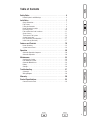
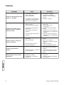
Table of Contents
Safety Rules . . . . . . . . . . . . . . . . . . . . . . . . . . . . . . . . . . . 4
Hazard Symbols and Meanings . . . . . . . . . . . . . . . . . . . . . . . . . . . . . . . . . . 4
Installation . . . . . . . . . . . . . . . . . . . . . . . . . . . . . . . . . . . . 7
Owner Orientation . . . . . . . . . . . . . . . . . . . . . . . . . . . . . . . . . . . . . . . . . . . . 7
Fuel Factors . . . . . . . . . . . . . . . . . . . . . . . . . . . . . . . . . . . . . . . . . . . . . . . . . 8
Lifting the Generator . . . . . . . . . . . . . . . . . . . . . . . . . . . . . . . . . . . . . . . . . . 8
Home Generator Location . . . . . . . . . . . . . . . . . . . . . . . . . . . . . . . . . . . . . . 9
Essential Circuits . . . . . . . . . . . . . . . . . . . . . . . . . . . . . . . . . . . . . . . . . . . . 10
Fuel and Electrical Inlet Locations . . . . . . . . . . . . . . . . . . . . . . . . . . . . . . . 11
Access Covers . . . . . . . . . . . . . . . . . . . . . . . . . . . . . . . . . . . . . . . . . . . . . . 11
The Gaseous Fuel System . . . . . . . . . . . . . . . . . . . . . . . . . . . . . . . . . . . . . 12
System Connectors . . . . . . . . . . . . . . . . . . . . . . . . . . . . . . . . . . . . . . . . . . 15
Final Installation Considerations . . . . . . . . . . . . . . . . . . . . . . . . . . . . . . . . 17
Initial Start-up (No Load). . . . . . . . . . . . . . . . . . . . . . . . . . . . . . . . . . . . . . 17
Features and Controls. . . . . . . . . . . . . . . . . . . . . . . . . . . . 18
Home Generator. . . . . . . . . . . . . . . . . . . . . . . . . . . . . . . . . . . . . . . . . . . . . 18
System Control Panel. . . . . . . . . . . . . . . . . . . . . . . . . . . . . . . . . . . . . . . . . 19
Operation . . . . . . . . . . . . . . . . . . . . . . . . . . . . . . . . . . . . 20
Automatic Operation Sequence . . . . . . . . . . . . . . . . . . . . . . . . . . . . . . . . . 20
Automatic Operation . . . . . . . . . . . . . . . . . . . . . . . . . . . . . . . . . . . . . . . . . 20
Maintenance . . . . . . . . . . . . . . . . . . . . . . . . . . . . . . . . . . 22
Servicing the System . . . . . . . . . . . . . . . . . . . . . . . . . . . . . . . . . . . . . . . . . 22
Fault Detection System . . . . . . . . . . . . . . . . . . . . . . . . . . . . . . . . . . . . . . . 22
Generator Maintenance . . . . . . . . . . . . . . . . . . . . . . . . . . . . . . . . . . . . . . . 24
Battery . . . . . . . . . . . . . . . . . . . . . . . . . . . . . . . . . . . . . . . . . . . . . . . . . . . . 25
Storage. . . . . . . . . . . . . . . . . . . . . . . . . . . . . . . . . . . . . . . . . . . . . . . . . . . . 26
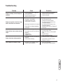
Troubleshooting. . . . . . . . . . . . . . . . . . . . . . . . . . . . . . . . 27
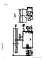
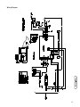
Schematic . . . . . . . . . . . . . . . . . . . . . . . . . . . . . . . . . . . . . . . . . . . . . . . . . 28
Wiring Diagram . . . . . . . . . . . . . . . . . . . . . . . . . . . . . . . . . . . . . . . . . . . . . 29
Warranty. . . . . . . . . . . . . . . . . . . . . . . . . . . . . . . . . . . . . 30
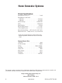
Product Specifications . . . . . . . . . . . . . . . . . . . . . . . . . . . 32
Common Service Parts . . . . . . . . . . . . . . . . . . . . . . . . . . . . . . . . . . . . . . . 32

4 BRIGGSandSTRATTON.COM
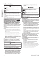
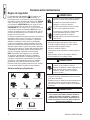
Safety Rules
The safety alert symbol ( ) is used with a signal word
(DANGER, CAUTION, WARNING), a pictorial and/or a safety
message to alert you to hazards. DANGER indicates a hazard
which, if not avoided, will result in death or serious injury.
WARNING indicates a hazard which, if not avoided, could
result in death or serious injury. CAUTION indicates a hazard
which, if not avoided, might result in minor or moderate
injury. NOTICE indicates a situation that could result in
equipment damage. Follow safety messages to avoid or
reduce the risk of injury or death.
The manufacturer cannot possibly anticipate every possible
circumstance that might involve a hazard. The warnings in
this manual, and the tags and decals affixed to the unit are,
therefore, not all-inclusive. If you use a procedure, work
method or operating technique that the manufacturer does
not specifically recommend, you must satisfy yourself that
it is safe for you and others. You must also make sure that
the procedure, work method or operating technique that you
choose does not render the generator system unsafe.
NOTE: Your generator is equipped with a spark arrester
muffler. The spark arrester must be maintained in effective
working order by the owner/operator. In the State of
California, a spark arrester is required by law (Section 4442
of the California Public Resources Code). Other states may
have similar laws. Federal laws apply on federal lands.
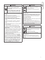
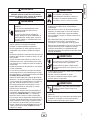
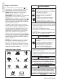
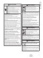
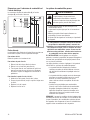
Hazard Symbols and Meanings
WARNING
Storage batteries give off explosive hydrogen
gas during recharging.
Slightest spark will ignite hydrogen and cause
explosion.
Battery electrolyte fluid contains acid and is
extremely caustic.
Contact with battery contents will cause severe
chemical burns.
A battery presents a risk of electrical shock and
high short circuit current.
DO NOT dispose of battery in a fire.
DO NOT allow any open flame, spark, heat, or lit cigarette
during and for several minutes after charging a battery.
DO NOT open or mutilate the battery.
Wear protective goggles, rubber apron, and rubber
gloves.
Remove watches, rings, or other metal objects.
Use tools with insulated handles.
•
•
•
•
•
•
WARNING
Running engine gives off carbon monoxide, an
odorless, colorless, poison gas.
Breathing carbon monoxide can cause
headache, fatigue, dizziness, vomiting,
confusion, seizures, nausea, fainting or death.
Operate generator ONLY outdoors.
Install a battery operated carbon monoxide alarm near
the bedrooms.
Keep exhaust gas from entering a confined area through
windows, doors, ventilation intakes, or other openings.
•
•
•
WARNING
The engine exhaust from this product contains chemicals
known to the State of California to cause cancer, birth
defects, or other reproductive harm.
WARNING
Certain components in this product and related
accessories contain chemicals known to the State
of California to cause cancer, birth defects or other
reproductive harm. Wash hands after handling.
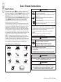
Save These Instructions
Explosion
Fire
Electrical Shock
Rotating Parts
Hot Surface
Toxic Fumes
Chemical BurnExplosive PressureAuto Start
Lift Hazard
Read Manual

5
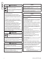
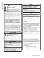
WARNING
Generator produces hazardous voltage.
Failure to properly ground generator can result
in electrocution.
Failure to isolate generator from power utility
can result in death or injury to electric utility
workers due to backfeed of electrical energy.
When using generator for backup power, notify utility
company.
DO NOT touch bare wires or receptacles.
DO NOT use generator with electrical cords which are
worn, frayed, bare or otherwise damaged.
DO NOT handle generator or electrical cords while
standing in water, while barefoot, or while hands or feet
are wet.
If you must work around a unit while it is operating,
stand on an insulated dry surface to reduce shock
hazard.
DO NOT allow unqualified persons or children to operate
or service generator.
In case of an accident caused by electrical shock,
immediately shut down the source of electrical power
and contact the local authorities. Avoid direct contact
with the victim.
Despite the safe design of the home generator, operating
this equipment imprudently, neglecting its maintenance
or being careless can cause possible injury or death.
Remain alert at all times while working on this
equipment. Never work on the equipment when you are
physically or mentally fatigued.
Before performing any maintenance on the generator,
disconnect the battery cable indicated by a NEGATIVE,
NEG or (-) first. When finished, reconnect that cable last.
After your home generator is installed, the generator
may crank and start without warning any time there is a
power failure. To prevent possible injury, always set the
generator’s system switch to OFF, remove the service
disconnect from the disconnect box AND remove the
15 Amp fuse BEFORE working on the equipment.
•
•
•
•
•
•
•
•
•
•
•
WARNING
Propane and Natural Gas are extremely
flammable and explosive.
Fire or explosion can cause severe burns or
death.
Install the fuel supply system according to applicable
fuel-gas codes.
Before placing the home generator into service, the fuel
system lines must be properly purged and leak tested.
After the generator is installed, you should inspect the
fuel system periodically.
NO leakage is permitted.
DO NOT operate engine if smell of fuel is present or other
explosive conditions exist.
DO NOT smoke around the generator. Wipe up any oil
spills immediately. Ensure that no combustible materials
are left in the generator compartment. Keep the area near
the generator clean and free of debris.
•
•
•
•
•
•
WARNING
Hazardous Voltage
Contact with power lines can cause electric
shock or burn.
Lifting Hazard / Heavy Object
Can cause muscle strain or back injury.
If lifting or hoisting equipment is used, DO NOT contact
any power lines.
DO NOT lift or move generator without assistance.
DO NOT lift unit by roof as damage to generator will
occur.
•
•
•

6 BRIGGSandSTRATTON.COM
WARNING
Contact with muffler area can result in serious
burns.
Exhaust heat/gases can ignite combustibles or
structures causing a fire.
DO NOT touch hot parts and AVOID hot exhaust gases.
Allow equipment to cool before touching.
DO NOT install the generator closer than 5 feet (1.5m)
from any combustibles or structures with combustible
walls having a fire resistance rating of less than 1 hour.
Keep at least minimum distances shown in
General
Location Guidelines to insure for proper generator
cooling and maintenance clearances.
Code of Federal Regulation (CFR) Title 36 Parks, Forests,
and Public Property require equipment powered by an
internal combustion engine to have a spark arrester,
maintained in effective working order, complying to
USDA Forest service standard 5100-1C or later revision.
In the State of California a spark arrester is required
under section 4442 of the California Public resources
code. Other states may have similar laws.
•
•
•
•
•
WARNING
Starter and other rotating parts can entangle
hands, hair, clothing, or accessories.
NEVER operate generator without protective housing or
covers.
DO NOT wear loose clothing, jewelry or anything that
may be caught in the starter or other rotating parts.
Tie up long hair and remove jewelry.
•
•
•
CAUTION
Installing the 15A fuse could cause the engine
to start.
Observe that the 15 Amp fuse has been removed from
the control panel for shipping.
DO NOT install this fuse until all plumbing and wiring has
been completed and inspected.
•
•
CAUTION
Excessively high operating speeds increase risk of injury
and damage to generator.
Excessively low speeds impose a heavy load.
DO NOT tamper with governed speed. Generator supplies
correct rated frequency and voltage when running at
governed speed.
DO NOT modify generator in any way.
•
•
NOTICE
Exceeding generators wattage/amperage capacity can
damage generator and/or electrical devices connected to
it.
See
Essential Circuits.
Start generator and let engine stabilize before connecting
electrical loads.
•
•
NOTICE
Improper treatment of generator can damage it and
shorten its life.
Use generator only for intended uses.
If you have questions about intended use, ask dealer or
contact Briggs & Stratton.
Operate generator only on level surfaces.
Adequate, unobstructed flow of cooling and ventilating air
is critical to correct generator operation.
The Oil Fill, Oil Drain and the Control Panel doors must be
installed whenever the unit is running.
DO NOT expose generator to excessive moisture, dust,
dirt, or corrosive vapors.
Despite the safe design of the home generator, operating
this equipment imprudently, neglecting its maintenance or
being careless can cause possible injury or death.
Remain alert at all times while working on this
equipment. NEVER work on the equipment when you are
physically or mentally fatigued.
DO NOT start engine with air cleaner or air cleaner cover
removed.
DO NOT insert any objects through cooling slots.
DO NOT use the generator or any of its parts as a step.
Stepping on the unit can cause stress and break parts.
This may result in dangerous operating conditions from
leaking exhaust gases, fuel leakage, oil leakage, etc.
If connected devices overheat, turn them off and
disconnect them from generator.
Shut off generator if:
-electrical output is lost;
-equipment sparks, smokes, or emits flames;
-unit vibrates excessively.
•
•
•
•
•
•
•
•
•
•
•
•
•

7
Installation
Save These Instructions
This manual contains important instructions that should be
followed during installation and maintenance of the generator
and battery.
Introduction
Thank you for your purchase of a Briggs & Stratton Home
Generator System. This product is intended for use as
an optional standby system which provides an alternate
source of electric power and to serve loads such as heating,
refrigeration systems, and communication systems that,
when stopped during any power outage, could cause
discomfort or the like. This product does not qualify for
emergency standby as defined by NFPA 70 (NEC).
This manual is an important document and should be
retained by the owner after installation has been completed.
This manual contains installation, startup and adjustment
instructions for a Home Standby Generator that supplies
120/240 Volt, single phase, 60Hz devices. The Home
Standby Generator may be operated on LP vapor or natural
gas fuel.
Every effort has been made to ensure that the information
in this manual is both accurate and current. However, the
manufacturer reserves the right to change, alter or otherwise
improve the generator at any time without prior notice.
Briggs & Stratton has made every effort to provide for a
safe, streamlined and cost-effective installation. Because
each installation is unique, it is impossible to know of and
advise the trade of all conceivable procedures and methods
by which installation might be achieved. Neither could we
know of possible hazards and/or the results of each method
or procedure. For these reasons,
Only current licensed electrical and plumbing contractors
should attempt Home Standby Generator installations.
Installations must strictly comply with all applicable
codes, industry standards and regulations.
Customer Responsibilities
• Read and follow the instructions given in this manual,
especially the section regarding selecting essential
circuits.
• Follow a regular schedule in maintaining, caring for and
using your home generator, as specified in this manual.
Installer Responsibilities
• Read and observe the safety rules.
• Install only an UL approved transfer switches that is
compatible with the home generator.
• Read and follow the instructions given in this
Installation, Start-up and Operator’s Manual.
IMPORTANT: If operating the generator below 40°F, it is
recommended that a battery warmer be installed. If operating
the generator below 32°F, a battery warmer must be
installed. This item is available at your local servicing dealer.
For the Home Owner:
To help you make informed choices and communicate
effectively with your installation contractor(s),
Read and understand Owner Orientation in this manual
before contracting or starting your home generator
installation.
To arrange for proper installation, contact the store at which
you purchased your Briggs & Stratton home generator, your
dealer, a licensed electrician or your utility power provider.
The home generator warranty is VOID unless the
system is installed by licensed electrical and plumbing
professionals.
The Emission Control System for this generator is warranted
for standards set by the U.S. Environmental Protection
Agency and by the California Air Resources Board (CARB).
For the Installing Dealer/Contractor:
For most applications, the Installation manual contains all
the information required to properly install and start the
home generator. This Operator’s Manual describes essential
circuit selection, routine operation and owner maintenance
procedures.
If you need more information, call (800) 743-4115, between
8:00 AM and 5:00 PM CT.
Owner Orientation
This section provides home generator owners with the
information necessary to achieve the most satisfactory and
cost effective installation possible.
The illustrations are for typical circumstances and are meant
to familiarize you with the installation options available with
your home generator. A thorough understanding of these
options will provide fundamental control over the cost of
your installation, as well as ensure your final satisfaction and
security.
Federal and local codes, appearance, noise levels, fuel types,
and distances are the factors that must be considered when
negotiating with an installation professional. Remember
that as the distance from the existing electrical service and
gaseous fuel supply increases, and the number of 90 degree
bends in the fuel supply increases; equal compensations
in piping and wiring materials must be allowed for. This
is necessary to comply with local codes and overcome
electrical voltage drops and gaseous fuel pressure drops.
The factors mentioned above will have a direct affect on
the overall price of your home generator installation.
NOTE: In some areas you may need to acquire electrical
permits for installing the home generator, building permits
for installing gas lines, and permits for noise allowances.
Your installer should check your local codes AND obtain the
permits before installing the system.

8 BRIGGSandSTRATTON.COM
Fuel Factors
An important consideration affecting the entire installation is
the type of fuel used by your home generator. The system
was factory tested and adjusted using either natural gas
or liquid propane (LP vapor). For proper engine function,
factors that are inherent to each of these fuels, your
location and the duration of possible utility interruptions are
important considerations in the following fuel guidelines:
• Use clean, dry fuel, free of moisture or any
particulate material. Using fuels outside the following
recommended values may cause performance problems.
• In engines set up to run on propane (LP), commercial
grade HD5 propane with a minimum fuel energy of
2500 BTUs/ft3 with maximum propylene content of
5% and butane and heavier gas content of 2.5% and
minimum propane content of 90%.
WARNING
Propane and Natural Gas are extremely
flammable and explosive.
Fire or explosion can cause severe burns or
death.
The home generator is equipped with an automatic safety
gas “fuel shut-off” valve.
DO NOT operate the equipment if the “fuel shut-off” valve
is missing or inoperative.
•
•
Power Decrease at High Altitude or High Temperature
Air density is less at high altitudes, resulting in less available
engine power. Specifically, engine power will decrease 3.5%
for each 1,000 feet (300 meters) above sea level and 1% for
each 10° F (5.6°C) above 77°F (25°C). Make sure you and
your installer consider these factors when determining total
generator load.
Unpacking Precautions
The unit is shipped bolted to its mounting pad, ready
for installation. Avoid damage from dropping, bumping,
collision, etc. Store and unpack carton with the proper side
up, as noted on the shipping carton.
CAUTION
Installing the 15A fuse could cause the engine
to start.
Observe that the 15 Amp fuse has been removed from
the control panel for shipping.
DO NOT install this fuse until all plumbing and wiring has
been completed and inspected.
•
•
Delivery Inspection
After removing the carton, carefully inspect the home
generator for any damage that may have occurred during
shipment.
IMPORTANT: If loss or damage is noted at time of delivery,
have the person(s) making delivery note all damage on the
freight bill and affix his signature under the consignor’s
memo of loss or damage. If loss or damage is noted after
delivery, separate the damaged materials and contact the
carrier for claim procedures. Missing or damaged parts are
not warranted.
Shipment Contents
The home generator is supplied with:
• Pre-attached mounting pad
• One flexible hook-up pipe (meets UL 569 and CSA 8.3)
• This installation, start-up and operator’s manual
• Installation checklist
• Oil drain tray
• Touch up paint
• One spare 15A fuse
• Roof hardware bag
• LP conversion kit
• 2 Pole connector - 240V from house
• 10 Pole connector - Sensing and control wires
• Remote LED indicator kit (red LED/plate/screws)
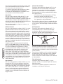
Lifting the Generator
The generator weighs more than 280 pounds. Proper tools,
equipment and qualified personnel should be used in all
phases of handling and moving the generator.
WARNING
Hazardous Voltage
Contact with power lines can cause electric
shock or burn.
Lifting Hazard / Heavy Object
Can cause muscle strain or back injury.
If lifting or hoisting equipment is used, DO NOT contact
any power lines.
DO NOT lift or move generator without assistance.
DO NOT lift unit by roof as damage to generator will
occur.
•
•
•
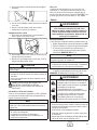
Lifting pockets are provided at each corner between the base
of the generator and its mounting pad. Retouch any chipped
paint with supplied touch-up paint.

9
Home Generator Location
Before installing generator, consult with homeowner and convey
the following guidelines which may affect the desired location.
WARNING
Exhaust heat / gasses can ignite combustibles
or structures causing a fire.
DO NOT install the generator closer than 5 feet (1.5m)
from any combustibles or structures with combustible
walls having a fire resistance rating of less than 1 hour.
Keep at least minimum distances shown in
General
Location Guidelines to insure for proper generator
cooling and maintenance clearances.
•
•
Generator Location
Install generator outdoors in an area which will not
accumulate deadly exhaust gas. DO NOT install generator
where exhaust gas could accumulate and enter inside or be
drawn into a potentially occupied building. Ensure exhaust
gas is kept away from any windows, doors, ventilation intakes
or other openings that can allow exhaust gas to collect in a
confined area. Prevailing winds and air currents should be
taken into consideration when positioning generator.
WARNING
Running engine gives off carbon monoxide, an
odorless, colorless, poison gas.
Breathing carbon monoxide can cause
headache, fatigue, dizziness, vomiting,
confusion, seizures, nausea, fainting, or death.
Operate generator ONLY outdoors.
Install a battery operated carbon monoxide alarm near
the bedrooms.
Keep exhaust gas from entering a confined area through
windows, doors, ventilation intakes, or other openings.
•
•
•
General Location Guidelines
• Install the unit outdoors ONLY.
• Place the unit in a prepared location that is flat and has
provisions for water drainage.
• Install the unit in a location where sump pump
discharge, rain gutter down spouts, roof run-off,
landscape irrigation, or water sprinklers will not flood
the unit or spray the enclosure and enter any air inlet
our outlet openings.
• Install the unit where the location of any services such
as phone, electrical, fuel, air conditioning, irrigation,
including covered, concealed and underground services
will not be affected or obstructed.
• Install the unit where air inlet and outlet openings will
not become obstructed by leaves, grass, snow, etc. If
prevailing winds will cause blowing or drifting, you may
need to construct a windbreak to protect the unit.
• Install the generator as close as possible to the
Transfer Switch and fuel supply to reduce the length of
wiring, conduit, and piping.
IMPORTANT: Laws or local codes may regulate the distance
to the fuel supply.
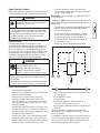
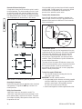
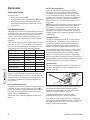
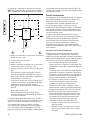
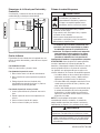
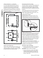
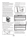
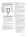
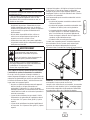
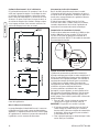
The Minimum (MIN) clearances from aerial view of generator
(B) to combustible (D), and non-combustible (A) materials is
shown below.
• These distances are provided to give generator location
guidance relative ONLY to combustibles, generator
cooling, and maintenance.
• The minimum distances in the figure are as shown.
All four sides of the generator cannot be enclosed
or restricted, even if the minimum distances are
maintained. DO NOT connect (A) and/or (D) to (E)
• A roof cannot be used.
• Exhaust (C) must not be allowed to accumulate.
A Non-Combustible material with Fire Resistant Rating of
1 hour or greater
B Home Generator System
C Engine Exhaust
D Combustible Material or Structure with a Fire
Resistance Rating of less than 1 hour.
E Any structure or material. DO NOT connect (A) and/or
(D) to (E).
The home generator is shipped already attached to its
mounting pad. Unless mandated by local code, a concrete
slab is not required.
If mandated by local code, construct a concrete slab at least
3 inches thick and 6 inches longer and wider than the unit.
Attach unit to slab with 1/4” diameter (minimum) masonry
anchor bolts long enough to retain the unit.
A
B
E
D
E
C
3’
(1m)
5’ (1.5m)
5’ (1.5m) 5’ (1.5m)
3’
(1m)
5’ (1.5m)

10 BRIGGSandSTRATTON.COM
Essential Circuits
As a home generator owner, it is important that you clearly
identify the circuits in your building that are “essential” to
you.
It is also important that your installer understand which
circuits you want to include as “Essential Circuits”.
Depending on the power consumed by these circuits, most
or all of them can be switched to the home generator for the
duration of normal power interruption.
The wattage reference table that follows will assist you with
your decision-making process. It provides the wattage used
by many ordinary household devices. Use it as a guide when
selecting your essential circuits. Review this information with
your installer and ask about any technical considerations that
might affect your installation. This chart serves as a guide
only. For exact wattage use an appropriate wattage meter.
Essential Circuit Selection
When selecting the essential circuits that will be switched
to “Standby Power,” it is important that the sum of the
combined circuit loads does not exceed the wattage/
amperage capacity of the generator. To help you with your
selection of essential circuits, please consider the following:
• Add up the total wattage of all electrical devices to be
connected at one time. This total should NOT be greater
than the generator’s wattage capacity.
The rated wattage of lights can be taken from light
bulbs. The rated wattage of tools, appliances and
motors can usually be found on a data plate or decal
affixed to the device.
• If the appliance, tool or motor nameplate does not
list wattage, multiply volts times the ampere rating to
determine watts (Volts x Amps = Watts).
Some electric motors (induction types) require about
three times more watts of power for starting than for
running. This surge lasts for only a few seconds. Be
sure you allow for this high starting wattage when
selecting electrical devices that will be energized by the
home generator:
• Figure the watts required to start the largest motor.
• Add that to the total running watts of all other
connected loads.
This Briggs & Stratton home generator complies with the
following “stationary standby power rating”:
The standby power rating is applicable for supplying
power for the duration of normal power interruption.
No sustained overload capability is available for this
rating.
Device
Running Watts
q
Air Conditioner (12,000 Btu)* 1700
q
Air Conditioner (24,000 Btu)* 3800
q
Air Conditioner (40,000 Btu)* 6000
q
Battery Charger (20 Amp) 500
q
Circular Saw (6-1/2”) 800 to 1000
q
Clothes Dryer (Electric)* 5750
q
Clothes Dryer (Gas)* 700
q
Clothes Washer* 1150
q
Coffee Maker 1750
q
Compressor (1 HP)* 2000
q
Compressor (1/2 HP)* 1400
q
Compressor (3/4 HP)* 1800
q
Curling Iron 700
q
Dehumidifier* 650
q
Electric Blanket 400
q
Electric Range (per element) 1500
q
Electric Skillet 1250
q
Freezer* 700
q
Furnace Fan (1/2 HP)* 800
q
Garage Door Opener* 500 to 750
q
Hair Dryer 1200
q
Hand Drill 250 to 1100
q
Iron 1200
q
Jet Pump* 800
q
Light Bulb 100
q
Microwave Oven 700 to 1000
q
Milk Cooler* 1100
q
Oil Burner on Furnace 300
q
Oil Fired Space Heater (140,000 Btu) 400
q
Oil Fired Space Heater (30,000 Btu) 150
q
Oil Fired Space Heater (85,000 Btu) 225
q
Radio 50 to 200
q
Refrigerator 700
q
Slow Cooker 200
q
Submersible Pump (1 HP)* 2000
q
Submersible Pump (1/2 HP)* 1500
q
Submersible Pump (1-1/2 HP)* 2800
q
Sump Pump* 800 to 1050
q
Table Saw (10”)* 1750 to 2000
q
Television 200 to 500
q
Toaster 1000 to 1650
*Allow three (3) times listed watts for starting device

11
This rating is applicable to installations served by a
reliable normal utility source. This rating is only applicable
to variable loads with an average load factor of 80% of
the standby rating. The standby rating is only applicable
for optional standby power where the generator set
serves as the backup to the normal utility source.
Use the wattage reference table provided and mark those
circuits you consider “critical” or “essential”. Make sure you
and your installer consider the system’s altitude above sea
level and the ambient temperature range when determining
total generator load.
IMPORTANT: When using the 100 Amp or 200 Amp transfer
switch with the home generator, you must turn off any non
essential loads. Failure to turn off non essential loads could
overload the generator causing it to shut down.
Some examples of non essential loads are as follows:
• Pool pump
• Hot tub
• Electric hot tub and/or pool heaters
• Central air conditioners
• Electric hot water heaters
• Electric range and/or oven
• Arc welder
• Non essential electric heaters
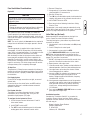
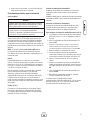
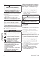
Fuel and Electrical Inlet Locations
The fuel inlet connector (A) and electrical inlet (B) is shown
below.
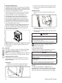
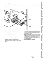
Access Covers
The home generator is equipped with an enclosure that has a
removable roof and an access cover for the control panel.
To Remove Roof:
Remove the four screws and lift off.
To Remove Access Cover:
1. Remove roof as described above.
2. Remove screw at top of access cover.
3. Pull access cover outward (away) from unit while pulling
cover upward and out of base. Cover will come free.
To Install Access Cover and Roof:
1. Guide bottom of access cover into base.
2. Push access cover until it is flush with sides.
3. Replace cover screw.
4. Replace roof and screws.
A
4.5”
13.5”
B

12 BRIGGSandSTRATTON.COM
The Gaseous Fuel System
WARNING
Propane and Natural Gas are extremely
flammable and explosive.
Fire or explosion can cause severe burns or
death.
LP gas is heavier than air and will settle in low areas.
Natural gas is lighter than air and will collect in high
areas.
The slightest spark can ignite these fuels and cause an
explosion.
DO NOT light a cigarette or smoke.
•
•
•
•
The information provided below is to assist gaseous fuel
system technicians in planning installations. In no way
should this information be interpreted to conflict with
applicable fuel gas codes. Consult with your local fuel
supplier or Fire Marshall if questions or problems arise.
TO THE INSTALLER: Consult with the home generator
owner(s) and convey any technical considerations that might
affect their installation plans before applying these general
guidelines.
The following general rules apply to gaseous fuel system
piping:
• The piping should be of a material that conforms to
federal and local codes, rigidly mounted and protected
against vibration.
• Piping should be protected from physical damage
where it passes through flower beds, shrub beds, and
other cultivated areas where damage could occur.
• Install the flexible, gaseous hose (supplied) between
the home generator Fuel Inlet port and rigid piping to
prevent thermal expansion or contraction from causing
excessive stress on the piping material.
NOTE: Where local conditions include earthquake, tornado,
unstable ground, or flood hazards, special consideration
shall be given to increase strength and flexibility of piping
supports and connections.
CAUTION
The supplied flexible gaseous pipe is not to be installed
underground or in contact with the ground.
The entire flexible gaseous pipe must be visible for
periodic inspection and must not be concealed within,
contact, or run through any wall, floor, or partition.
•
• Piping must be of the correct size to maintain the
required supply pressures and volume flow under
varying generator load conditions with all gas appliances
connected to the fuel system turned on and operating.
• Use an approved pipe sealant or joint compound on all
threaded fittings to reduce the possibility of leakage.
• Installed piping must be properly purged and leak
tested, in accordance with applicable codes and
standards.
WARNING
Propane and Natural Gas are extremely
flammable and explosive.
Fire or explosion can cause severe burns or
death.
Before placing the home generator into service, the fuel
system lines must be properly purged and leak tested.
NO leakage is permitted.
•
•
Consider the following factors when planning to install the
fuel supply system:
The home generator engine is fitted with a fuel mixer system
that meets the specifications of the California Air Resources
Board for “tamper-proof” fuel systems.
• A minimum of one accessible, approved manual shutoff
valve shall be installed in the fuel supply line within
6 ft (1.8 m) of the home generator. A union or flanged
connection shall be provided downstream from this
valve to permit removal of controls.
• Natural gas fuel supply pressure at the generator’s fuel
inlet port should be between 5 to 7 inches of water (in.
W.C.) at full load with all gas appliances turned on and
operating.
• LP gas fuel supply pressure should be 11 to 14 inches
of water (in. W.C.) at full load with all gas appliances
turned on and operating.
The Home Generator has been factory set to run on natural
gas. If you need to change from natural gas to LP gas,
the unit will need to be reconfigured, as described in Fuel
System Selection.
It is recommended that the fuel connection incorporate the
following components:
• A manual fuel shut-off valve located in the interior of
the building.
• A manual fuel shut-off valve located outside the
building, just before the generator unit.
• Where the formation of hydrates or ice is known to
occur, piping should be protected against freezing. The
termination of hard piping should include a sediment
trap where condensate is not likely to freeze.
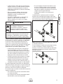
• A manometer port should be provided.

13
The manometer port permits temporary installation of a
manometer to ensure that the engine receives the correct
fuel pressure to operate efficiently throughout its operating
range.
NOTE: A digital manometer, P/N 19495, is available at your
local Briggs & Stratton service center.
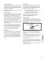
When the initial test runs are completed, the manometer
is removed and the port is plugged. A typical final fuel
connection assembly is shown here, where (A) is the fuel
supply and (B) goes to the home generator.
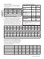
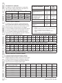
Fuel Consumption
Estimated fuel supply requirements at half and full load for
natural gas and LP vapor fuels are shown below.
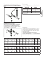
Fuel Pipe Sizing
The tables below provide the maximum capacity of pipe in
cubic feet of gas per hour for gas pressures of 0.5 psi or
less and a pressure drop of 0.3 in. water column. Specific
gravity of gas is shown.
Listed values compensate for a nominal amount of
restriction from bends, fittings, etc. If an unusual number of
fittings, bends, or other restrictions are used, please refer to
federal and local codes.
B
A
Natural Gas LP Vapor
1/2 Load Full Load 1/2 Load Full Load
80 C 137 C 33 C 56 C
80,000 B 137,000 B 82,500 B 140,000 B
C = Cubic feet per hour
B = BTU’s per hour
NPT 10ft 15ft 20ft 30ft 40ft 50ft 60ft 70ft 80ft 90ft 100ft
1/2” 168 146 115 93 79 70 63 59 55 51 48
3/4” 346 293 240 192 163 145 132 120 113 106 99
1” 653 549 446 360 307 274 250 230 211 197 187
Natural Gas Pipe Size - Gas Flow chart, in cubic feet per hour, specific gravity=0.65
NPT 10ft 15ft 20ft 30ft 40ft 50ft 60ft 70ft 80ft 90ft 100ft
1/2” 110 96 76 61 52 46 42 38 36 33 32
3/4” 277 192 158 126 107 95 87 79 74 69 65
1” 428 360 293 236 202 180 164 151 139 129 123
Liquid Propane (LP) Gas Pipe Size - Gas Flow chart, in cubic feet per hour, specific gravity=1.50

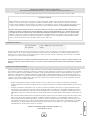
14 BRIGGSandSTRATTON.COM
Physical Properties LP Vapor Natural
Gas
Normal Atmospheric State Gas Gas
Boiling Point (in °F):
Initial
End
-44
-44
-259
-259
Heating Value:
BTU per gallon (Net LHV*)
BTU per gallon (gross**)
Cubic feet (gas)
83,340
91,547
2,500
63,310
1,000
Density*** 36.39 57.75
Weight† 4.24 2.65
Octane Number:
Research
Motor
110+
97
110+
* LHV (Low Heat Value) is the more realistic rating.
** Gross heat value does not consider heat lost in the form of water
during combustion.
*** Density is given in “Cubic Feet of Gas per Gallon of Liquid”.
† Weight is given in “Pounds per Gallon of Liquid”.
Fuel Comparison Chart
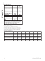
Required Propane Tank Size
The required size of the propane tank at various
temperatures when kept at least half full is shown below
in the chart. Given the gas withdrawal rate and the lowest
average winter temperature, an installer can specify the
required LP storage tank size.
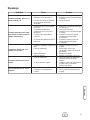
Withdrawal Rate 32° F 20° F 10° F 0° F -10° F -30° F -40° F
50 CFH 115 115 115 250 250 400 600
100 CFH 250 250 250
400 500 1000 1500
150 CFH
300 400 500 500 1000 1500 2500
200 CFH
400 500 750 1000 1200 2000 2500
300 CFH 750 1000 1500 2000 2500 4000 5000

15
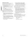
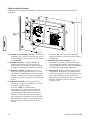
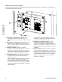
System Connectors
Low voltage connections to signal fault contacts, transfer switch communication, remote LED and auxiliary 12VDC power are
made to a removable ten-pin connector plug. Compare this illustration with your generator to familiarize yourself with the
location of these important connections:
A - 2 Pole Connector Plug
B - 240 Volt Utility — Use to hook up the 240V utility leads
from the transfer switch to the generator.
C - +12 Volt DC, .5 Amp Output — Internal auxiliary power
supply.
D - Remote LED Output — Used to connect to the remote
LED supplied with the generator. The remote LED will
turn on and off in a series of blinks if certain faults are
detected in the generator.
E - Transfer Switch Communication — Connect TxRx and
TxRx GND to transfer switch to monitor transfer switch
functions.
F - Fault Contacts — Use NO, COM and NC for operating a
siren, light, optional GenAlert, etc. to alert you in case
of a fault. Contacts reverse state (NO goes to NC and
vice versa) upon a fault condition.
G - 10 Pole Connector Plug
B
A
C
D
E
F
G

16 BRIGGSandSTRATTON.COM
Generator AC Connection System
A single-phase, three-wire AC connection system is used in
the home generator. The stator assembly consists of a pair
of stationary windings with two leads brought out of each
winding. The junction of leads 22 and 33 forms the neutral
lead. Keep field wiring to a minimum. A complete schematic
and wiring diagram can be found later in this manual.
NOTE: Neutral is not bonded to ground at generator.
Grounding the Generator
Ground the home generator per applicable codes, standards,
and regulations. The generator GND lug is located in the
control panel box.
Utility Circuit Connection
“240V Utility” leads must be routed in conduit. The
“240V Utility” leads deliver power to the generator’s circuit
board, optional battery warmer and oil warmer. This power
also charges the battery. When power on these leads is lost,
the generator will start.
Using provided 2 pole connector plug and installer-supplied
minimum 300V, 14 AWG copper wire, connect each control
circuit terminal in the generator to the two-amp fuse
terminals in the automatic transfer switch.
Transfer Switch Communication
Using #18 AWG twisted pair conductors, no greater than
200 ft in length, connect Tx Rx and Tx Rx Ground from the
generator control panel to the GND and T/R on the transfer
switch control board.
Fault Detection System
The generator may have to run for long periods of time with
no operator present. For that reason, the system is equipped
with sensors that automatically shut down the generator
in the event of potentially damaging conditions, such as
low oil pressure, high temperature, over speed, and other
conditions. Refer to Fault Detection System in Maintenance
for more detailed information.
The owner will use the remote LED indicator to observe the
status of the home generator system. Consult with the owner
for a convenient location. Locate the electrical box in an
area visible by the home owner such as near a garage door
opener or security control panel.
To install the remote LED indicator:
1. Push the LED through the mounting plate from the
front until it snaps in place.
IMPORTANT: The LED is polarity sensitive.
2. Using provided 10 pole connector and installer-supplied
minimum 18AWG wire, connect the remote LED to the
generator control board +LED and GND connection.
Use wire nuts to attach wire to LED leads.
3. Attach mounting plate to installer-supplied electrical box.
Generator
Transfer
Switch

17
Final Installation Considerations
Engine Oil
NOTICE
Any attempt to crank or start the engine before it has been
properly serviced with the recommended oil will result in
equipment failure.
Refer to
Maintenance and engine manual for oil fill
information.
Damage to equipment resulting from failure to follow this
instruction will void engine and generator warranty.
•
•
This engine is shipped from the factory pre-run and filled
with synthetic oil (API SJ/CF 5W-30W). This allows for
system operation in the widest range of temperature and
climate conditions. Before starting the engine, check oil level
and ensure that engine is serviced as described in the engine
operator’s manual.
NOTE: The use of synthetic oil does not alter the required oil
change intervals described in the engine operator’s manual.
Battery
The home generator is supplied with a sealed, lead-acid,
rechargeable, 12 Volt DC 33 Amp-Hour, 350 cold cranking
amps (CCA), valve regulated battery. It is installed in the unit
and the battery cables are connected at the factory.
With the battery installed, all wiring to transfer switch and
home generator completed, utility power supplied to the
Automatic Transfer Switch, and the system switch in the
AUTO position, the battery receives a trickle charge while the
engine is not running. The trickle charge cannot be used to
recharge a battery that is completely discharged.
15 Amp Fuse
The generator’s 15 Amp fuse was removed at the factory to
prevent the unit from starting during shipping. Your installer
will ensure the fuse is properly installed upon completion of
the installation.
Fuel Supply System
Ensure that all fuel pipe connections are tight, secure and
without leaks.
Ensure that all gas line shutoff valves are OPEN and that
adequate fuel pressure is available whenever automatic
operation is desired.
Fuel System Selection
The engine of your Home Generator System is factory
calibrated to run on natural gas (NG). It may also be
operated on liquid propane (LP) vapor.
To configure the fuel system for LP use:
1. LP fuel inlet pressure must be between 11 and 14
inches water column.
2. Set AUTO/OFF switch to OFF.
3. Turn OFF the main distribution panel circuit breaker
sending power to the automatic transfer switch.
4. Remove 15 Amp fuse.
5. Change main jet in fuel mixer following instruction
sheet provided in LP conversion kit.
6. Reinstall 15 Amp fuse.
7. Turn
ON the main distribution panel circuit breaker that
supplies utility power to the automatic transfer switch.
8. Set AUTO/OFF switch to AUTO.
9. Reset exercise timer following instructions Setting
Exercise Timer.
The generator is now ready to operate automatically using
LP fuel. With a fixed main jet for LP gas, there is no need to
perform any engine adjustments for LP operation.
Initial Start-up (No Load)
Before operating the home generator or placing it into
service, inspect the entire installation carefully.
Then begin testing the system without any electrical loads
connected, as follows:
1. Set generator’s main circuit breaker to its ON (closed)
position.
2. Install 15 Amp fuse in control panel.
3. Set generator’s system switch to AUTO.
4. Push MANUAL OVER-RIDE button on control panel.
NOTE: When the home generator is started for the very
first time, it will require that air in the gaseous fuel lines be
purged. This may take a few minutes.
5. DO NOT crank engine for more than 10 seconds, then
pause for 10 seconds to reduce heat in the starter.
6. Repeat process until engine starts.
7. Listen for unusual noises, vibration or other indications of
abnormal operation. Check for oil leaks while engine runs.
8. Let engine warm up for about five minutes to allow
internal temperatures to stabilize.
9. Connect an RMS AC voltmeter and a frequency meter
to check generator output at load side of circuit
breaker. Voltage should be 230-240 Volts, frequency
should be 62.0 - 62.5 Hz.
10. Check generator output between one of the generator
connection lugs and the neutral lug, then between the
other generator connection lug and the neutral lug.
In both cases, voltage reading should be between
115-120 Volts.
11. Push and hold MANUAL OVER-RIDE button on control
panel again until engine stops.
Installation Inspection
Complete the ”Installation Checklist” as you make the
inspection. Ensure all items have been filled-in and all
signatures have been obtained. Instruct the owner to mail
the white copy to:
Briggs & Stratton Power Products
Warranty Registration
P. O. Box 239
Jefferson, WI 53549-0239

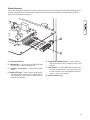
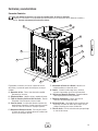
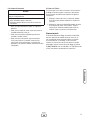
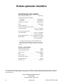
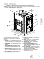
18 BRIGGSandSTRATTON.COM
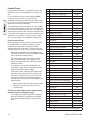
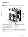
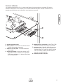
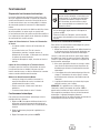
Generator is shown with roof, plastic access cover and
control panel cover removed for clarity.
A - Air Cleaner — Uses a dry type filter element and foam
precleaner to protect engine by filtering dust and debris
out of intake air.
B - Engine Label — Identifies engine model and type.
C - Oil Fill Cap/Dipstick — Check and add recommended
engine oil here.
D - Control Panel — Used for various test, operation and
maintenance functions. See System Control Panel on the
next page.
E - Oil Drain Hose — Located inside access cover on side
panel. Provided to facilitate oil changing.
F - Unit Identification Label — Identifies unit by serial
number.
G - Battery — 12 Volt DC, sealed battery provides power to
start the engine.
H - Lifting Pocket — Provided at each corner for lifting
generator.
J - Fuel Inlet — Attach appropriate fuel supply to generator
here.
K - Exhaust Port — High-performance muffler lowers engine
noise to comply with most residential codes.
L - Oil Filter — Filters engine oil to prolong generator life.
D
A
C
E
B
G
K
H
J
L
F
Features and Controls
Home Generator
Read this Operator’s Manual and Safety Rules before operating your generator.
Compare the illustrations with your generator to familiarize yourself with the locations of various controls and
adjustments. Save this manual for future reference.

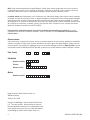
19
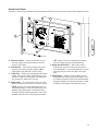
System Control Panel
Compare this Control Panel illustration with your generator to familiarize yourself with the location of these important controls:
A - Set Exercise Switch — Used to set the exercise cycle
start time and day-of-the-week. Exercise cycle only
occurs in AUTO mode.
B - Circuit Breaker — Protects the generator from shorts
and other over-current conditions. Must be ON to
supply power to the Automatic Transfer Switch.
C - 15 Amp Fuse — Protects the home generator DC control
circuits. If the fuse has ‘blown’ (melted open) or was
removed, the engine cannot crank or start. Replace the
fuse using only an identical ATO 15A fuse.
D - System Switch — This two-position switch is the most
important control on the system and is used as follows:
• “AUTO” position is the normal operating position. If a
utility power outage is sensed, the system will start the
generator. When utility power is restored, AUTO lets
the engine stabilize internal temperatures, shuts off the
generator, and waits for the next utility power outage.
• “OFF” position turns off running generator, prevents
unit from starting and resets any detected faults.
E - Manual Over-Ride Switch — With system switch in
AUTO position, push the manual over-ride switch to
start the generator. To turn off the generator, push and
hold the manual over-ride switch again until engine
stops.
F - Digital Display — Displays the total number of hours
the generator has been running and fault codes. Used
to schedule maintenance tasks and for troubleshooting
operational problems with the home generator. All fault
conditions are described in Fault Detection System.
B
A
C
D
E
F

20 BRIGGSandSTRATTON.COM
Operation
Automatic Operation Sequence
The generator’s control panel houses a logic control circuit
board. This control board constantly monitors utility power
source voltage. Should that voltage drop below a preset level,
control board action will signal the engine to crank and start.
When utility source voltage is restored above a preset
voltage level, the engine is signaled to shut down.
The actual system operation is not adjustable and is sequenced
by sensors and timers on the control board, as follows:
Utility Voltage Dropout Sensor
• This sensor monitors utility source voltage.
• If utility source voltage drops below about 70 percent
of the nominal supply voltage, the sensor energizes a
10 second timer. The timer is used to ‘sense’ brown-outs.
• Once the timer has expired, the engine will crank and
start.
Utility Voltage Pickup Sensor
This sensor monitors utility power supply voltage. When that
voltage is restored above 80 percent of the nominal source
voltage, a time delay starts timing and the engine will go to
engine cool-down.
Engine Cool-down Timer
• When the load is transferred back to the utility power
source, the engine cool-down timer starts timing.
• The timer will run for about one minute, then the
generator will stop.
• Minimum engine run time is 5 minutes.
Automatic Operation
To select automatic operation, do the following:
1. Set the main distribution panel circuit breaker that
sends utility voltage to the transfer switch to ON.
2. Set the generator’s main circuit breaker to its ON
position.
3. Set the system switch to AUTO.
CAUTION
With the system switch set to AUTO, the engine
may crank and start at any time without warning.
Such automatic starting normally occurs when
utility source voltage drops below a preset level
or during the normal exercise cycle.
To prevent possible injury that may be caused by such
sudden starts, always set the system switch to OFF.
Remove the 15 Amp fuse before working on or around
the generator or transfer switch.
•
•
Checking Automatic Operation
To check the system for proper automatic operation, proceed
as follows:
1. Turn OFF the main distribution panel circuit breaker
sending power to the automatic transfer switch.
The engine will crank and start when the utility voltage drops
out and the sensor has timed out. Let the system go through
its entire automatic operation sequence.
2. With the generator output supplying its loads, turn ON
the main distribution panel circuit breaker that supplies
utility power to the automatic transfer switch.
3. The automatic transfer switch will transfer loads back
to the utility power after 5 minute minimum run time
and utility is restored.
4. The generator will run for an additional one minute for
engine cool down, then shut down.
NOTE: If utility is restored and generator does not shut down
after 10 minutes, set system switch to OFF and contact your
installer or local service center.
This completes the test procedures for automatic operation.
The home generator will now start automatically when utility
power is lost and will supply power to the transfer switch.
Page is loading ...
Page is loading ...
Page is loading ...
Page is loading ...
Page is loading ...
Page is loading ...
Page is loading ...
Page is loading ...
Page is loading ...
Page is loading ...
Page is loading ...
Page is loading ...
Page is loading ...
Page is loading ...
Page is loading ...
Page is loading ...
Page is loading ...
Page is loading ...
Page is loading ...
Page is loading ...
Page is loading ...
Page is loading ...
Page is loading ...
Page is loading ...
Page is loading ...
Page is loading ...
Page is loading ...
Page is loading ...
Page is loading ...
Page is loading ...
Page is loading ...
Page is loading ...
Page is loading ...
Page is loading ...
Page is loading ...
Page is loading ...
Page is loading ...
Page is loading ...
Page is loading ...
Page is loading ...
Page is loading ...
Page is loading ...
Page is loading ...
Page is loading ...
Page is loading ...
Page is loading ...
Page is loading ...
Page is loading ...
Page is loading ...
Page is loading ...
Page is loading ...
Page is loading ...
Page is loading ...
Page is loading ...
Page is loading ...
Page is loading ...
Page is loading ...
Page is loading ...
Page is loading ...
Page is loading ...
Page is loading ...
Page is loading ...
Page is loading ...
Page is loading ...
Page is loading ...
Page is loading ...
Page is loading ...
Page is loading ...
Page is loading ...
Page is loading ...
Page is loading ...
Page is loading ...
-
 1
1
-
 2
2
-
 3
3
-
 4
4
-
 5
5
-
 6
6
-
 7
7
-
 8
8
-
 9
9
-
 10
10
-
 11
11
-
 12
12
-
 13
13
-
 14
14
-
 15
15
-
 16
16
-
 17
17
-
 18
18
-
 19
19
-
 20
20
-
 21
21
-
 22
22
-
 23
23
-
 24
24
-
 25
25
-
 26
26
-
 27
27
-
 28
28
-
 29
29
-
 30
30
-
 31
31
-
 32
32
-
 33
33
-
 34
34
-
 35
35
-
 36
36
-
 37
37
-
 38
38
-
 39
39
-
 40
40
-
 41
41
-
 42
42
-
 43
43
-
 44
44
-
 45
45
-
 46
46
-
 47
47
-
 48
48
-
 49
49
-
 50
50
-
 51
51
-
 52
52
-
 53
53
-
 54
54
-
 55
55
-
 56
56
-
 57
57
-
 58
58
-
 59
59
-
 60
60
-
 61
61
-
 62
62
-
 63
63
-
 64
64
-
 65
65
-
 66
66
-
 67
67
-
 68
68
-
 69
69
-
 70
70
-
 71
71
-
 72
72
-
 73
73
-
 74
74
-
 75
75
-
 76
76
-
 77
77
-
 78
78
-
 79
79
-
 80
80
-
 81
81
-
 82
82
-
 83
83
-
 84
84
-
 85
85
-
 86
86
-
 87
87
-
 88
88
-
 89
89
-
 90
90
-
 91
91
-
 92
92


Simplicity 7000 WATT 206484GS User manual
- Category
- Power generators
- Type
- User manual
Ask a question and I''ll find the answer in the document
Finding information in a document is now easier with AI
in other languages
Related papers
-
Simplicity 040222B-0 User manual
-
-
-
-
-
-
-
-
-
Other documents
-
Briggs & Stratton 18000 User manual
-
Briggs & Stratton Power Supply 202826GS User manual
-
-
-
-
Briggs & Stratton 10000 Watt Home Generator System User manual
-
-
-
-
Briggs & Stratton Portable Generator 01975-0 User manual