
DL240
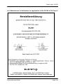
Data Logger DL240
Operating Manual and Installation Instructions
Operating Manual: 73015765 SW version: from V2.04
Issued 13.11.2006 (d) Edition:
This product is discontinued!

Data Logger DL240
Elster-Instromet GmbH Page 2

Data Logger DL240
Elster-Instromet GmbH Page 3
All rights reserved.
Copyright © 1999-2006 Elster-Instromet GmbH, D-55252 Mainz-Kastel
All details and descriptions in this operating manual and installation instructions have been
given only after careful checking. Despite this however, the possibility of errors cannot be
completely eliminated. Therefore, no guarantee can be given for completeness or for the
content. Also, the manual cannot be taken as giving assurance with regard to product
characteristics. Furthermore, characteristics are also described in it that are only available
as options.
The right is reserved to make changes in the course of technical development. We would
be very grateful for suggestions for improvement and notification of any errors, etc.
With regard to extended product liability the data and material characteristics given
should only be taken as guide values and must always be individually checked and
corrected where applicable. This particularly applies where safety aspects must be
taken into account.
Passing this manual to third parties and its duplication, in full or in part, are only allowed
with written permission from Elster-Instromet GmbH.
Mainz-Kastel, November 2006

Data Logger DL240
Elster-Instromet GmbH Page 4
Contents
I Safety information 7
II Items supplied and accessories 8
II-1 Included items 8
II-2 Ordering data and accessories 8
1 Brief description 9
1.1 Functions and performance features 9
2 Operation 13
2.1 Front panel 13
2.2 Displaying values 14
2.3 Formation of the list structure 14
2.3.1 Movement within the list structure 14
2.3.2 Summary charts, List Structure 1 15
2.3.3 Summary charts, submenus "U1" – "U7" 18
2.3.4 LCD special characters and function of the arrows 19
2.4 Changing values 20
2.4.1 Differentiating between values (operating classes) 20
2.4.2 Input function 21
2.4.3 Entry errors 22
2.5 Securing the values 23
2.5.1 Calibration lock and calibration switch 23
2.5.2 Supplier and customer locks 23
3 Functional description 24
3.1 Volume and signal input list (E1-E4) 24
3.1.1 Description of the values 25
3.2 Archives in the DL240 30
3.2.1 Setting the counters for archiving 30
3.2.2 Values common in all archives 31
3.2.3 Structure of month archive Input x / computation counter 32
3.2.4 Structure of measurement period archive, Input x 34
3.2.5 Measurement period and memory depth 35
3.2.6 Application as flow recording device 35
3.2.7 Application as high flow display device 36
3.2.8 Use of the "HT/LT changeover" 37
3.2.9 System interface 39
3.2.10 Reading out archives 40
3.3 Computation Counter (R1) 43
3.3.1 Description of the values 44
3.3.2 Application: Measurement period archive for computation counter 44

Data Logger DL240
Elster-Instromet GmbH Page 5
3.4 System list 46
3.4.1 Description of the values 46
3.5 Service list 49
3.5.1 Description of the values 49
3.6 Output list 52
3.6.1 Setting as fixed value output (remote function) 52
3.6.2 Setting as pulse output 52
3.6.3 Setting as switching output 54
3.7 Interface list 55
3.7.1 Description of the values 55
3.7.2 Optical interface (Interface 1) 60
3.7.3 Modem operation in the DL240 (Interface 2) 60
3.7.4 Short messages in the DL240 (SMS function) 60
3.8 Logbook list 64
3.8.1 Description of the values 64
3.8.2 Submenu: Status register 65
3.8.3 Submenu: Momentary status 65
3.8.4 Submenu: Logbook 66
3.8.5 The status register 67
3.8.6 Deleting the status message 67
3.8.7 Overview of message numbers 68
3.8.8 Explanation of the messages 69
3.8.9 Events in the DL240 71
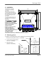
4 Installation 80
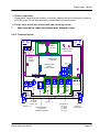
4.1 Mounting options 80
4.2 Installation procedure 81
4.2.1 Mounting the device 81
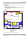
4.2.2 Terminal layout 83
4.2.3 Functional inspection 84
4.2.4 Sealing 84
4.2.5 Seal layout 85
4.2.6 Putting the link to the WinLIS software into operation 86
4.3 Maintenance 87
4.3.1 Battery replacement 87
4.3.2 Recalibration of the DL240 89
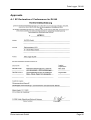
Approvals 90
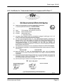
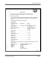
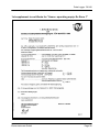
A-1 EC Declaration of Conformance for DL240 90
A-2 Certificate for "Associated electrical equipment Ex Zone 1" 92
A-3 Manufacturer's declaration for application of the DL240 in Ex Zone 2 104
B Technical data 110
B-1 General data (mechanical) 110
B-2 Power supply 110

Data Logger DL240
Elster-Instromet GmbH Page 6
B-3 Pulse / signal inputs 111
B-4 Signal and pulse outputs 111
B-5 Optical interface 112
B-6 Internal, serial TTL interface 112
B-7 Measurement uncertainty 112
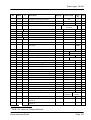
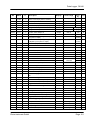
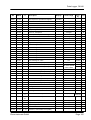
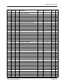
C Value index 113
D Status messages 125
E Operator interface, inputs / computation channel 126
F Operator interface system - logbook 127
G Index 128

Data Logger DL240
Elster-Instromet GmbH Page 7
I Safety information
F The connections of the DL240 are freely accessible during setting up. Therefore,
make sure that no electrostatic discharge (ESD) can occur in order to avoid damage
to the components. The person carrying out the installation can, for example,
discharge himself/herself by touching the potential equalisation line.
F To avoid erroneous operation and problems, the operating manual must be read
before putting the DL240 into operation. In particular the descriptions in Chapter 4
should be followed.
In the device there are modules which are approved as "associated electrical
equipment" in Category "ib" according to DIN EN 50020 with intrinsically safe circuits (s.
Chap.A-2). This means that the DL240 is suitable for the connection of pulse generators
and signals which are located in areas subject to explosion hazards. As stated on the
manufacturer's declaration, the DL240 itself is rated for application in Ex Zone 2 (see
Chap. A-3).
When operating the device as "associated electrical equipment", it is essential to follow
the instructions below:
F Follow the regulations in the relevant standards, in particular DIN VDE 0165.
F For the installation and operation of the DL240 follow the DVGW guidelines for the
construction and operation of gas measurement systems as well as the appropriate
PTB guidelines.
F Make sure that the limits quoted in Appendix B for the devices to be connected are not
exceeded.
F The DL240 must be connected by the PA terminal on the CPU board to the
potential equalisation strip without interruption.
When operating the device in Ex Zone 2, it is essential to follow the instructions below:
F Refer to the manufacturer's declaration in Chap.A-3!
The DL240 can be optionally supplied with mains voltage at 230 V. Mains voltage is
highly dangerous!
F The installation and any modification must only be carried out by appropriately
trained personnel.
F Only switch on the mains voltage when all cables have been connected. When
making modifications to the connections, it is essential to make sure that there is no
voltage present on the device and that it is secured against switch-on.

Data Logger DL240
Elster-Instromet GmbH Page 8
II Items supplied and accessories
II-1 Included items
The following items are included with the DL240:
a) Data Logger DL240
b) Dispatch list
c) Design data sheet
d) Operating Manual
e) 4 cable glands, 2 internal hinges and var. hardware
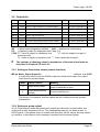
II-2 Ordering data and accessories
Data Logger DL240
• Complete device 834 80 050
• Basic device (without accessories
and batteries) 730 15 763
Accessories
• Operating manual, English 730 15 765
• Plug-in terminal, 2-pole black 041 30 407
• Calibration covering cap 730 15 777
• Battery module 730 17 964
• Cable tie, releasable (for battery) 040 90 124
• Interior hinges (mounting aid) 041 95 034
• IR readout head 730 15 883
• KD-100/PS2 direct readout cable 730 15 152
Options
• Power supply, 230V (incl. accessories) 730 15 770
• Standard modem, 14k4 (incl. accessories) 730 16 757
• ISDN modem (incl. accessories) 730 17 117
• GSM modem - Wavecom (incl. accessories)
• GSM antenna housing 730 17 320
• External modem connection (incl. accessories) 730 16 941
• RS232/RS485 interface (incl. accessories) 730 16 909
• Ethernet card (incl. accessories) 730 17 688
• CS interface (incl. accessories) 730 17 709

Data Logger DL240
Elster-Instromet GmbH Page 9
1 Brief description
1.1 Functions and performance features
General:
The Data Logger DL240 is intended to be used as a battery operated, compact device for
the acquisition and storage of counting pulses and / or level changes for various types of
energy in applications subject to official calibration.
Four counter/signalling inputs, separate from one another, from the Ex area or outside of
the Ex area (any combination possible).
Acquisition and archiving of meter readings and maxima separately for each channel.
System monitoring (signalling function) with appropriate reactions, locally via outputs or via
remote data transmission (SMS message) to a GSM recipient (with modem
option).
Optional: Various modems (analogue, ISDN or GSM) with external power supply.
Power supply:
Battery operation for acquisition unit; service life depending on operating mode ≥ 8 years.
Battery replacement possible without loss of data and without violation of calibration seals.
Data back-up of all system data and relevant billing data (e.g. month-end readings,
maxima...) without battery supply using EEPROM.
Connection to external 230 VAC supply possible.
Operator interface:
12-character LCD display, description of values with short designations.
Operation via 4 cursor keys, special functions by operation of two keys.
Programming via keypad possible.
Calibration switch (separately sealed in the device).
Access to the device via different levels possible:
Calibration official, manufacturer, supplier or customer.
Adjustable write and read rights for various values.
Pulse / signal inputs:
4 intrinsically safe inputs (programmable as pulse or signal inputs).
Mixed operation of all inputs possible (intrinsically safe or non-intrinsically safe).
Connection possibility provided for reed contacts and transistor switches.
Maximum counting frequency 10 Hz.
Various counters for each input (totaliser, adjustable counter, current measuring period
counter, current day counter and, where possible, for HT/LT selection).

Data Logger DL240
Elster-Instromet GmbH Page 10
Pulse / signal outputs:
2 transistor outputs (switching to ground), each freely programmable as pulse, alert,
warning output, limit monitoring, time-synchronous output.
Remote switching of outputs possible using parameterising software.
Pulse duration adjustable on pitch of 125 ms (max. output frequency: 4 Hz)
Output buffer can be read out (memory depth: 65535 pulses)
Data interface:
Optical interface according to IEC 1107.
Internal TTL interface for modem connection (alternative):
– various internal modems (analogue, ISDN, GSM),
– use of an external modem via RS-232 / RS-485 interface,
– connection of Ethernet bus,
– connection of external modem with CS interface (CL0, passive, max. 19200 Bd).
Mechanical details / housing:
Wall-mounted housing, 160x160x90mm (WxHxD)
Optional: External mounting feet, top-hat rail mounting or panel-mounting frame
Mounting and device installation without breaking the calibration seals.
Temperature range for basic unit: -25°C...+60°C;
temperature range with various options: see Annex. B.
Class of protection: IP 64, non-condensing atmosphere.
Approvals:
PTB approval as high-flow display device for the media gas and water.
PTB approval as flow recording device for the media gas and water.
Associated operating equipment for Ex Zone 1 (also in modem mode)
Application in Ex Zone 2 possible also in modem mode (according to DIN VDE 0165)
National / European telecommunications approval (constituent part of modem).
Software:
Event-controlled archiving of counter readings:
a) 4 counting channels (E1-E4): approx. 173 days with 60 min. measurement period or 6
weeks for 15 min. (depends on status messages).
b.) Month end readings (2 adjustable counters) and day and measurement period maxima
for E1-E4 and computation counter: 15 months
c.) Logbook: 250 entries
Manual possibility for backing up all counter readings.
Backing up of all system data after a change.

Data Logger DL240
Elster-Instromet GmbH Page 11
Automatic saving of date and all counter readings 1x per day
Display of the archived values possible on the display incl. skip function in the archive
Computation of measurement period value (consumption) in archive possible on-line.
Setting of the counters to be archived (2 counters for each archive).
Separate read-out modes for supplier, customer, maintenance and network operator (i.e.
support of up to 4 independent read-out parties possible).
Provision of a day boundary separately for each channel; value can be called into display.
HT/LT switchover; display of current counter and condition at switchover.
Display of the momentary flow.
Pulse summation function possible via computation counter.
Measurement period of 1...60 min. and 1...24 h adjustable separately for each channel.
Display of remaining time for current measurement period.
Display of current daily and measurement period consumptions on display.
Display of last daily and last measurement period consumptions on display.
Provision of a measuring point label according to association agreement.
Also non-decade pulse values can be programmed separately for each channel.
Three modes for the selection of summer/winter time (none, automatic, manual setting).
Completely programmable via interface.
Modem functions, general:
Data transmission via modem or other remote data transfer devices.
Remote adjustment of all values possible depending on lock status.
Programmable number of ringing tones before accepting call.
Access monitoring for readout and setting of values via locks.
Two time frames programmable for receiving calls.
Spontaneous message via SMS (see below).
Participation on an IEC1107 bus system (connection formation with device address).
GSM mode (optional):
GSM modem with SIM card holder can be integrated.
External GSM antenna (approx. 3m), optional with housing as screening.
PIN support for SIM card security.
Display of network operator and reception strength.
Auto-login once per day and before sending an SM.
SM initiation for test purposes possible on device.

Data Logger DL240
Elster-Instromet GmbH Page 12
Sending short messages (SMS):
Instant message via SMS and D1 or D2 networks to a control station (with GSM modem)
or mobile phone based on messages occurring in the DL240.
Sending of an SM to up to two recipients possible.
Customised setting of up to 8 values which are to be sent by SMS (incl. short designation
and unit); adjustable separator of individual values.
SMS mode not possible via external modems with CS interface.
Monitoring functions
Monitoring of signalling inputs with appropriate reactions (e.g. warning, entries in the
logbook, signal on outputs, sending a short message).
Monitoring of programmable limits with appropriate reactions (e.g. signalling via outputs,
sending a short message).
Internal monitoring of the HW and SW functions in the device with appropriate reactions
(e.g. signalling via outputs, sending a short message).

Data Logger DL240
Elster-Instromet GmbH Page 13
2 Operation
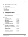
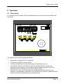
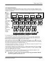
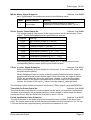
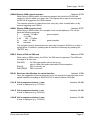
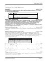
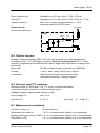
2.1 Front panel
For operation an LCD display with 160 segments and four cursor keys is provided on the
front panel:
The display has the following display features:
• Single-line text display with 12 characters.
• Ten special symbols in the top margin.
• Four arrow symbols in the right-hand margin for identifying the unit.
• Ten indicator arrows in the bottom margin for identifying the list in which the
displayed value is located, one indicator arrow for showing whether the value is
calibrated and one indicator arrow for the interface status.
• There are four keys on the front panel for operating the DL240. When a key is
pressed, a corresponding movement occurs within the list structure. Special functions
can be executed by pressing two keys simultaneously.
Data Logger
Nicht geeicht !
Write enabled
ESC
HOME ENTER
CLR
DL240
E1
E2
Service
E3 R1
E4 System Logbuch
Schnittstelle
Logbook
Interface
Ausgang
Output
Made in Germany
3201234
online
m³
1/m³
m³/h
min
Fabr.Nr./Ser.No:
Baujahr/Year:
2002

Data Logger DL240
Elster-Instromet GmbH Page 14
2.2 Displaying values
Identification of the data on the 12-character display occurs using abbreviated
designations. Generally, an abbreviated designation consists of up to four letters which
appear at the left end of the display. The right-hand eight places are normally used for
displaying numerical values.
The corresponding address can be superimposed for unambiguous identification of the
displayed values using the display "Help" function (see Chap 0 ). The significance of the
address is explained in Appendix 0 .
2.3 Formation of the list structure
The data display in the DL240 is structured in a tabular form. The individual columns in the
table each contain associated values.
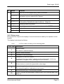
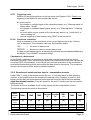
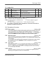
2.3.1 Movement within the list structure
Key(s) Designation Action
"↑" Arrow key,
top
Upwards movement
within the current list: From the first value
in the list movement is then to the last value.
"↓" Arrow key,
bottom
Downwards movement within the current list: From the end of
the list movement is then to the first value.
"←" Arrow key,
left
Skip from any value within a table to the top value of the
column to the left.1
"→ " Arrow key,
right
Skip from any value within a table to the top value of the
column to the right.1
"↓ ↑" ENTER Activate entry mode, open submenu or update
measurements.
"← ↑" HOME/CLR Skip to the top row of the current column or to left field (Field
1,1) within a matrix.
"↓ →" ESC Skip from a submenu to the menu immediately above.
"← →" HELP Calls the address of the displayed value.
Note: Key function during operation: See Chap. 2.4
1 With similar lists (e.g.: Input 1-4), skipping to the similar value in the adjacent list occurs.

Data Logger DL240
Elster-Instromet GmbH Page 15
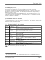
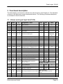
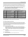
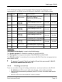
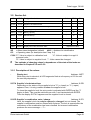
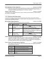
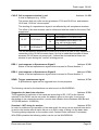
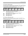
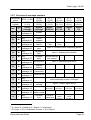
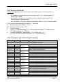
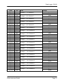
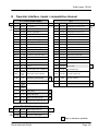
2.3.2 Summary charts, List Structure 1
E1 – E4 (Counter input) E1 – E4 (Status input)
⇔
Vx Main counter x (1≤ x ≤ 4) or ST.Ex Status signal input Ex
⇔
to Vx.LT LT counter x MD.Ex Mode input x to
"Log
book"
Vx.T Totaliser x MD.ME Mode for monitoring Ex "R1"
Vx.P Counter, adjustable x
Qx Flow rate x
L.ME Limit for monitoring input Ex
HT.LT Event for switchover HT/LT
MD.Ex Mode, input x
MD.ME Mode for monitoring x
SC.ME Source for monitoring x
CP.Ex cp value, input x
SN.M Serial no., meter (places 1-4) and
with arrow right places 5-12
DS.Ca DS-100 number for
Counter "a" in archive
DS.Cb DS-100 number for
Counter "b" in archive
Cu.No Customer number input x
MP.Ex Measurement period input x
MP.RE Remaining time in meas. period
Vx.MP Incr. meas. period counter Ex
VxM.L Last meas. period value Ex
Vx.MP Max. meas. per. counter
Ex current month U1
DY.Ex Day boundary for input x
Vx.DT Current day counter input x
VxD.L Last day value input x
Vx.DT Max. day counter input x
current month U2
Arx.1 Month archive input x U3
Arx.2 Meas. period archive Ex U4
Frx.2 Meas. period archive Ex frozen
Note:
• x (1≤ x ≤ 4) signifies that "x" can take on the value 1...4 in the abbreviated designation;
e.g.: V1, V2, V3 or V4
• Meaning of the abbreviated designations: See Chapter 3 and Appendix 0 .
• So-called submenus, which are explained in the following tables, are arranged under
"U1" - "U7" (see Chapter: 2.3.3).

Data Logger DL240
Elster-Instromet GmbH Page 16
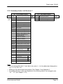
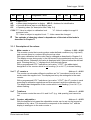
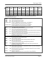
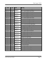
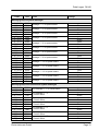
2.3.2 Summary charts, List Structure 2
R1
⇔
R1 Comp. counter Vx (e.g. ∑ V1-V4)
⇔
to R1.LT Comp. counter Vx.LT to
"E4" R1.T Comp. counter Vx.T "System"
R1.P Comp. counter, Vx.P
Q.R1 Flow R1
L.ME Limit for monitoring R1
MD.R1 Mode R1
MD.ME Mode for monitoring R1
SC.ME Source for monitoring R1
DS.Ca DS-100 number for
Counter "a" in archive
DS.Cb DS-100 number for
Counter "b" in archive
Cu.No Customer no., comp. counter
MP.R1 Measurement period R1
MP.RE Remaining time for meas. per.
R1.MP Incr. meas. period counter R1
R1M.L Last meas. period value R1
R1.MP Max. meas. period counter
R1 current month U1
DB.R1 Day boundary, comp. counter
R1.DT Incr. day counter R1
R1D.L Last day value R1
R1.DT Max. day counter current
month R1 U2
Ar5.1 Month archive R1 U3
Note:
• Meaning of the abbreviated designations: See Chapter 3 and Appendix C .
• So-called submenus, which are explained in the following tables, are arranged under
"U1" - "U7" (see Chapter: 2.3.3).

Data Logger DL240
Elster-Instromet GmbH Page 17
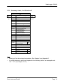
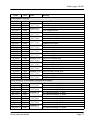
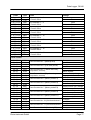
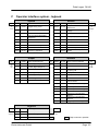
2.3.2 Summary charts, List Structure 3
System Service
⇔
TIME Time and with "→ " to date
⇔
- Display test
⇔
to MOD.T Summer / winter time on/off L.STA Supplier's combination
status/close to
"R1" M.CYC Measurement cycle L.COD Supplier's combination
enter/change
"Output"
DISP Permanent display on/off
BAT.R Residual service life of battery
AUT.V Time to automatic display
changeover
BAT.C Battery capacity
Fa.No Fabrication no. DL240
BACK Backup all data
VER.1 Software version, application
CLR.V Clear counter (incl. archive)
VER.2 Software version, driver
CLR.X Execute restart
CHK.1 Checksum, application
Add User-specific display
CHK.2 Checksum driver
Misc Value of user-specific display
Output Interface
⇔
MD.A1 Mode, Signal Output A1
⇔
MD.S2 Mode, internal interface
⇔
to SC.A1 Source, Signal Output A1
DF.S2 Data format, internal interface to
"Service"
CP.A1 cp value, Signal Output A1
Bd.S2 Baud rate, internal interface "Logbook"
SM.A1 Signal for Status Output A1 NUM.T Number of ringing tones before
accepting call.
MD.A2 Mode, Signal Output A2
GSM.N Network operator
SC.A2 Source, Signal Output A2
GSM.L GSM reception level
CP.A2 cp value, Signal Output A2
RES.P Status, SIM card PIN (GSM)
SM.A2 Signal for Status Output A2 Bd.S1 Baud-rate identification, optical
interface
CA1.B Call Acceptance Window 1, start
CA1.E Call Acceptance Window 1, end
CA2.B Call Acceptance Window 2, start
CA2.E Call Acceptance Window 2, end
RES.1 Response to Spont. Signal 1
RES.2 Response to Spont. Signal 2
SEND Release spontaneous signal
Logbook
⇔
S.REG Status register U5
⇔
to STAT Momentary status U6 to
"Interfac
e"
CLR Clear status register "E1"
LOGB Logbook U7

Data Logger DL240
Elster-Instromet GmbH Page 18
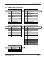
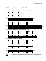
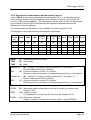
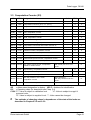
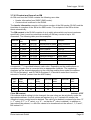
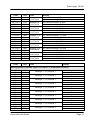
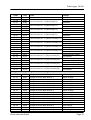
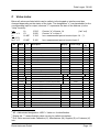
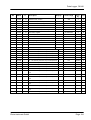
2.3.3 Summary charts, submenus "U1" – "U7"
U1 Submenu: "Max. measurement period counter E1 - E4 in current month"
to date ⇔ TIME ⇔ (Date) ⇔
to TIME
U2 Submenu: "Max. day counter E1 - E4 in current month"
to date ⇔ TIME ⇔ (Date) ⇔
to TIME
U3 Archive: "Month archive E1 - E4 / computation channel"
to Er.Ch ⇔ ABNo
⇔ TIME ⇔ (Date) ⇔ C"a" ⇔ C"b" ⇔
to VxM.L
⇔ ABNo
⇔ TIME ⇔ (Date) ⇔ C"a" ⇔ C"b" ⇔
⇔ ABNo
⇔ TIME ⇔ (Date) ⇔ C"a" ⇔ C"b" ⇔
to Vx.LT ⇔ VM.L ⇔ TIME ⇔ (Date) ⇔ STAT ⇔
to VxT.L
⇔ VM.L ⇔ TIME ⇔ (Date) ⇔ STAT ⇔
⇔ VM.L ⇔ TIME ⇔ (Date) ⇔ STAT ⇔
to STAT ⇔ VT.L ⇔ TIME ⇔ (Date) ⇔ STAT ⇔ ST.x ⇔ ST.SY ⇔ Er.Ch ⇔
⇔ VT.L ⇔ TIME ⇔ (Date) ⇔ STAT ⇔ ST.x ⇔ ST.SY ⇔ Er.Ch ⇔
to ABNo
⇔ VT.L ⇔ TIME ⇔ (Date) ⇔ STAT ⇔ ST.x ⇔ ST.SY ⇔ Er.Ch ⇔
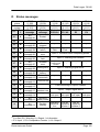
U4 Archive: "Measurement period archive E1 – E4"
to Er.Ch ⇔ ABNo
⇔ TIME ⇔ (Date) ⇔ C"a" ⇔
D
"a"
⇔
to Vx.LT
⇔ ABNo
⇔ TIME ⇔ (Date) ⇔ C"a" ⇔ D"a" ⇔
⇔ ABNo
⇔ TIME ⇔ (Date) ⇔ C"a" ⇔ D"a" ⇔
to DVx ⇔ C"b" ⇔
D
"b"
⇔ ST.x ⇔ ST.SY ⇔ S.TE ⇔ Er.Ch ⇔
to ABNo
⇔ C"b" ⇔ D"b" ⇔ ST.x ⇔ ST.SY ⇔ S.TE ⇔ Er.Ch ⇔
⇔ C"b" ⇔ D"b" ⇔ ST.x ⇔ ST.SY ⇔ S.TE ⇔ Er.Ch ⇔
U5 Submenu: "Status register, total"
to SR.4 ô SR.SY
ô SR.1 ô SR.2 ô SR.3 ô SR.4 ô to SR.SY
2:100
1:111 2:111 3:111 4:111
U6 Submenu: "Momentary status, total"
to ST.4 ô ST.SY
ô ST.1 ô ST.2 ô ST.3 ô ST.4 ô to ST.SY
2:100
1:110 2:110 3:110 4:110
U7 Archive: "Logbook"
to Er.Ch ⇔ ABNo
⇔ TIME ⇔ (Date) ⇔ S.TE ⇔ Er.Ch ⇔
to ABno
⇔ ABNo
⇔ TIME ⇔ (Date) ⇔ S.TE ⇔ Er.Ch ⇔
⇔ ABNo
⇔ TIME ⇔ (Date) ⇔ S.TE ⇔ Er.Ch ⇔
Note: Meaning of the abbreviated designations: See Chapter 3 and Appendix 0 .

Data Logger DL240
Elster-Instromet GmbH Page 19
The entries marked in bold and italic text depend on the programming
of the archive entries (see Chapter 0 ).
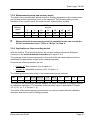
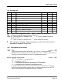
2.3.4 LCD special characters and function of the arrows
The special characters positioned in the top margin of the LCD have the following
meaning:
_ The value located in the display is a mean value.
∆ The value located in the display is a counter increment (consumption).
min Label for a minimum.
max Label for a maximum.
ARCHIV The value in the display is an archive value, i.e. it has been saved due to a
defined event.
PROG The segment is illuminated while the calibration lock is open.
WARN Display of the current device status. A flashing segment indicates that the
cause of the disturbance is actively present on the DL240. Constant
illumination means that the cause is no longer present on the device, but
the status message in the status register has not been acknowledged.
BATT The segment flashes when the computed battery service life has fallen
below the limit (default: three months).
The ten left arrows in the bottom margin on the display are used for orientation and for
better identification of the relevant displayed value. A "column heading" of the display list
(see Chap. 0) is assigned to each arrow. For each value the relevant associated arrow is
switched on (e.g. display TIME -> Arrow "System").
The two right arrows at the lower margin of the display have the following meaning:
- Arrow "Not calibrated"
Indicates to the user that the value located in the display is not calibrated and therefore
may not be used for billing purposes. The function can only be switched off for non-
calibrated applications.
- Arrow "On-line"
Flashes during the time in which a link exists via the optical interface or via the internal
interface (e.g. via modem).
The arrows located in the right-hand margin of the display point to the units printed on the
front membrane. The corresponding arrow is turned on when displaying values with units.
All the right-hand arrows flash, except the arrow which, if applicable, indicates a unit, for
indicating a possible branch to a submenu (e.g. "Logbook").
When operation is currently located in a submenu, the arrows in the lower margin of the
display flash except the arrow pointing to the present display list.

Data Logger DL240
Elster-Instromet GmbH Page 20
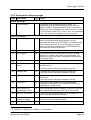
2.4 Changing values
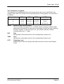
2.4.1 Differentiating between values (operating classes)
The methods of changing values differ depending on the value. These are therefore
subdivided into so-called "operating classes". Each value in an operating class is treated
identically on entry. The following operating classes are present in the DL240:
Type OC1
Description Change via "ENTER"
Constant 1 Value is permanently specified
No change possible
Measurements 2 Value determined by
measurement (e.g. flow rate) Displayed value is updated.
Permanent
values 3 Parameters (e.g. serial
number, cP value)
Change possible depending on
state of lock; values can be
changed in permissible range.
Discrete values 4
Parameters which can only
assume a few permanently
defined values (e.g.: Mode,
input)
Change possible depending on
state of lock; values can be
changed in predefined range.
Initial. values 5
Values which can only be set
to their initial value (e.g.:
status register).
Change possible depending on
state of lock; values can be
changed to initial values.
Trigger function
6 Functions which can be
triggered via keypad (e.g.
Clear counter).
Change possible depending on
state of lock; trigger by
changeover to "1" and terminating
with "Enter".
Combination 7 Opening / closing the
supplier's lock.
Similar to "Permanent values", but
with masked entry.
Archive values 8
Display of the archived values
possible in Operating Classes
1-3.
No change possible.
- 9 Not used in the DL240.
Headings
10 /
11
Heading for archives (10) or
submenus (11).
Branching to the appropriate menu
(submenu)
1 OC: Operating Class; each value is assigned to one of the 11 operating classes
Page is loading ...
Page is loading ...
Page is loading ...
Page is loading ...
Page is loading ...
Page is loading ...
Page is loading ...
Page is loading ...
Page is loading ...
Page is loading ...
Page is loading ...
Page is loading ...
Page is loading ...
Page is loading ...
Page is loading ...
Page is loading ...
Page is loading ...
Page is loading ...
Page is loading ...
Page is loading ...
Page is loading ...
Page is loading ...
Page is loading ...
Page is loading ...
Page is loading ...
Page is loading ...
Page is loading ...
Page is loading ...
Page is loading ...
Page is loading ...
Page is loading ...
Page is loading ...
Page is loading ...
Page is loading ...
Page is loading ...
Page is loading ...
Page is loading ...
Page is loading ...
Page is loading ...
Page is loading ...
Page is loading ...
Page is loading ...
Page is loading ...
Page is loading ...
Page is loading ...
Page is loading ...
Page is loading ...
Page is loading ...
Page is loading ...
Page is loading ...
Page is loading ...
Page is loading ...
Page is loading ...
Page is loading ...
Page is loading ...
Page is loading ...
Page is loading ...
Page is loading ...
Page is loading ...
Page is loading ...
Page is loading ...
Page is loading ...
Page is loading ...
Page is loading ...
Page is loading ...
Page is loading ...
Page is loading ...
Page is loading ...
Page is loading ...
Page is loading ...
Page is loading ...
Page is loading ...
Page is loading ...
Page is loading ...
Page is loading ...
Page is loading ...
Page is loading ...
Page is loading ...
Page is loading ...
Page is loading ...
Page is loading ...
Page is loading ...
Page is loading ...
Page is loading ...
Page is loading ...
Page is loading ...
Page is loading ...
Page is loading ...
Page is loading ...
Page is loading ...
Page is loading ...
Page is loading ...
Page is loading ...
Page is loading ...
Page is loading ...
Page is loading ...
Page is loading ...
Page is loading ...
Page is loading ...
Page is loading ...
Page is loading ...
Page is loading ...
Page is loading ...
Page is loading ...
Page is loading ...
Page is loading ...
Page is loading ...
Page is loading ...
Page is loading ...
-
 1
1
-
 2
2
-
 3
3
-
 4
4
-
 5
5
-
 6
6
-
 7
7
-
 8
8
-
 9
9
-
 10
10
-
 11
11
-
 12
12
-
 13
13
-
 14
14
-
 15
15
-
 16
16
-
 17
17
-
 18
18
-
 19
19
-
 20
20
-
 21
21
-
 22
22
-
 23
23
-
 24
24
-
 25
25
-
 26
26
-
 27
27
-
 28
28
-
 29
29
-
 30
30
-
 31
31
-
 32
32
-
 33
33
-
 34
34
-
 35
35
-
 36
36
-
 37
37
-
 38
38
-
 39
39
-
 40
40
-
 41
41
-
 42
42
-
 43
43
-
 44
44
-
 45
45
-
 46
46
-
 47
47
-
 48
48
-
 49
49
-
 50
50
-
 51
51
-
 52
52
-
 53
53
-
 54
54
-
 55
55
-
 56
56
-
 57
57
-
 58
58
-
 59
59
-
 60
60
-
 61
61
-
 62
62
-
 63
63
-
 64
64
-
 65
65
-
 66
66
-
 67
67
-
 68
68
-
 69
69
-
 70
70
-
 71
71
-
 72
72
-
 73
73
-
 74
74
-
 75
75
-
 76
76
-
 77
77
-
 78
78
-
 79
79
-
 80
80
-
 81
81
-
 82
82
-
 83
83
-
 84
84
-
 85
85
-
 86
86
-
 87
87
-
 88
88
-
 89
89
-
 90
90
-
 91
91
-
 92
92
-
 93
93
-
 94
94
-
 95
95
-
 96
96
-
 97
97
-
 98
98
-
 99
99
-
 100
100
-
 101
101
-
 102
102
-
 103
103
-
 104
104
-
 105
105
-
 106
106
-
 107
107
-
 108
108
-
 109
109
-
 110
110
-
 111
111
-
 112
112
-
 113
113
-
 114
114
-
 115
115
-
 116
116
-
 117
117
-
 118
118
-
 119
119
-
 120
120
-
 121
121
-
 122
122
-
 123
123
-
 124
124
-
 125
125
-
 126
126
-
 127
127
-
 128
128
-
 129
129


Ask a question and I''ll find the answer in the document
Finding information in a document is now easier with AI
Related papers
-
Elster AS-200/S2 Operating instructions
-
-
-
-
-
-
-
-
-
Other documents
-
Honeywell FE260 Operating instructions
-
-
-
-
Honeywell EK205-M User manual
-
Rosemount IMPS 4000 Intelligent Multiprobe Test Gas Sequencer-Rev 1.0 Owner's manual
-
-
Allen-Bradley SLC 500 Series User manual
-
-
ITT Controls RMG UNIGUARD Owner's manual