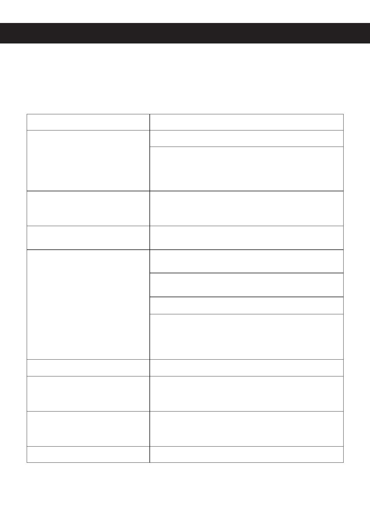
SZSMT CW-5200 Series User manual

Type
User manual

The SZSMT CW-5200 Series industrial refrigeration chiller is designed for precise temperature control in various applications. With its intelligent thermostat, it maintains consistent temperatures, with adjustable parameters for customized cooling. The chiller features multiple alarms for overheating, overchilling, and flow issues, ensuring reliable operation. Its compact size and easy installation make it suitable for tight spaces and quick setup. The CW-5200 Series is ideal for cooling laser engravers, CNC spindles, and other equipment requiring precise temperature control.

The SZSMT CW-5200 Series industrial refrigeration chiller is designed for precise temperature control in various applications. With its intelligent thermostat, it maintains consistent temperatures, with adjustable parameters for customized cooling. The chiller features multiple alarms for overheating, overchilling, and flow issues, ensuring reliable operation. Its compact size and easy installation make it suitable for tight spaces and quick setup. The CW-5200 Series is ideal for cooling laser engravers, CNC spindles, and other equipment requiring precise temperature control.

CW-5200 SERIES
INDUSTRIAL REFRIGERATION CHILLER
USER MANUAL
Read Carefully Before Use
Keep for Future Reference
V20220496
1
SAFETY INFORMATION
DO NOT run this chiller without rst providing adequate water. (See page 3.) Deionized or
distilled water is preferrable.
ONLY use with stable, compatible, and well-grounded power supplies. See page 5 for the
correct voltage for your model.
Place this chiller in a well-ventilated, dry environment away from heat sources but warm
enough to avoid freezing temperatures.
Leave at least 1 foot (30 cm) of space behind the rear air outlet.
Leave at least 4 inches (10 cm) of space around the two side air inlets.
Do not allow children or untrained persons to use this chiller.
Pay attention to possible condensation on the chiller and its water lines. If condensation is
observed, raise the water temperature, keep the water lines and cooled components warmer,
or reduce ambient humidity until no condensation occurs.
When cooling a laser engraver, take care that this device does not cause the room's humidity
to exceed safe levels.
Do not all the air lter to become blocked by dust. Clean it regularly.
Disconnect the power and drain all water from the chiller before storage or transport.
Remember that the OUTLET of the water chiller should connect to the INLET of the product
to be cooled. Similarly, the water chiller's inlet should be connected to the other machine's
water outlet.
Warning!
Caution!
PACKAGE LIST
1 × Industrial Chiller
1 × Power Cord
1 × Alarm Signal Output Plug
1 × Spare Fuse (held near the rear power socket)
1 × Instruction Manual
2
PARTS DIAGRAM
FRONT
WATER INJECTION PORT
AIR INLET & FILTER
ALARM OUTPUT TERMINAL
POWER SOCKET & SPARE FUSE
COOLING WATER OUTLET
COOLING WATER INLET
AIR OUTLET
AIR OUTLET
WATER LEVEL GAUGE
MACHINE PARAMETERS
SERIAL NO.
WATER DRAIN
BACK
TEMPERATURE CONTROLLER
FLOW ALARM (red)
NORMAL FLOW (green)
POWER SWITCH
3
INSTALLATION
It is very simple to install this industrial chiller.
1. Open the package to check that the machine is intact and all the
necessary accessories are included.
2. Open the injection port and add water. For best results, use deionized
water.
Use the water level gauge and ensure the level is in the middle or top
of the NORMAL (green) area. Pour slowly and do not allow the water
to overow.
For cooling carbon steel equipment, the water should have the
appropriate amount of anticorrosive additive.
3. Connect the water inlet and outlet pipes to the system you wish to
cool. Be sure to connect the chiller's OUTLET pipe to your system's
INLET port and the chiller's inlet pipe to the system's outlet port.
4. Plug in the power and flip the power switch. The pump will begin
working.
There may be some bubbles at rst. These should disappear after a
minute or two.
Don't worry if the fans and other components of the chiller do not
activate. They are usually automatically controlled (see p. 5) and will
not begin working until they are needed by the machine.
In dierent conditions, the time for startup may vary from seconds to
a few minutes. Do not become frustrated and switch the machine on
and o, except when necessary to add water.
5. Check the water level of the water tank again, as in Step 2 above.
The water level of the chiller will lower somewhat as it lls the cooling
path of your machine. If necessary, carefully add more water to the
chiller to maintain the level in the NORMAL (green) area.
If the water level drops sharply or continues to go down during normal
use, turn o your devices and examine the water pipes and cooling
path for leakage. Repair any such leaks before restarting the devices
and continuing work.
6. Adjust the parameters of the device as needed.
The CW-5200 has an intelligent thermostat and normally does not
need any adjustment. If it becomes necessary, refer to the next page.
RET
SET
4
OPERATION AND ADJUSTMENT
The new P-608 intelligent temperature controller does not need to adjust its parameters in normal
circumstances. It will self-adjust its parameters according to the ambient room temperature to
meet its cooling requirements.
The new P-608 intelligent temperature controller has a separate default, maintaining a constant
77°F (25°C). Users can adjust this value as needed.
The two controllers have the same functions and operating system, apart from their default modes.
1. CONTROL PANEL
(1) Indicators D1 & D2 above convey the following information:
(2) Press ▼ to show the ambient room temperature. D1 will ash. After 3 seconds, the display will
revert to its previous default.
(3) ▲ and ▼ adjust the display status and the values of the parameters.
(4) RET enters commands.
(5) SET allows parameters to be changed and reset.
ON: The thermostat is adjusting water temperature according to the room temperature.
OFF: The thermostat is maintaining a constant water temperature.
FLASHING: The thermostat is accepting new parameters from the user or showing the
ambient room temperature.
RET
SET
D1
ON: The chiller is working in its refrigeration mode.
OFF: The chiller is working in its insulation mode.
FLASHING: The chiller is working in its energy-saving mode.
D2
P-608
5
2. Restoring factory settings
Before the machine starts up, press and hold and until the controller displays rE. 3 seconds
after releasing the buttons, the control panel will resume working with all parameters restored to
their factory defaults.
3. Thermostat parameters list
4. General settings adjustment
(1) Press SET to enter the user-dened parameter mode. D1 will ash.
(2) In constant temperature mode, the rst screen will be F0, showing the temperature the chiller
will keep the water. Press or to change the value. After you have chosen a value, press
RET to save it and exit. Pressing SET will exit without saving your changes. Waiting more than 20
seconds to choose an action will also exit without saving any changes.
(3) In intelligent control mode, the first screen will be F1, showing the control panel for the set
temperature dierence between the water and air in degrees Celsius. Adjust its value in the same
way.
Order Code Item Range P-608
Defaults
P-608
Defaults Note(s)
1F0 Water Temperature F9–F8 25 25 Celsius value of constant
temperature mode
2 F1 Temperature Dierence −15 to +5 −2 −2
Celsius value of the
dierence between water
and air temperatures in
intelligent control mode
3F2 Cooling Hysteresis 0.1–3.0 0.8 0.1
4 F3 Control Mode 0–1 10
1 is intelligent control mode
0 is constant temperature
mode
5 F4 Overheated Water Alarm 1–20 10 10
6F5 Overchilled Water Alarm 1–20 15 15
7 F6 Overheated Room Alarm 40–50 45 45
8F7 Password 00–99 8 8
9F8 Highest Allowed Water Temperature F0–40 30 30
10 F9 Lowest Allowed Water Temperature 1–F0 20 20
6
5. Advanced settings adjustment
(1) Press ▲ and then hold SET until 0 is displayed.
(2) Press to choose the one or two digit passcode. (The factory default is 08.) Press SET
again.
(3) If the password is correct, F0 is shown and D1 will ash. (If the password is incorrect, the
system will exit to its default display.)
(4) Press ▲ or ▼ to cycle through the parameters mentioned on p. 6.
(5) Press SET to select one of these parameters to adjust.
(6) Press or to adjust its value. Press RET to save your changes and exit. Pressing SET
will exit to the previous menu level without saving your changes. Waiting more than 20 seconds
to choose an action will also exit without saving any changes.
(7) No changes will take effect until you have used RET to save the changes and exited
parameter adjustment, returning to normal operation.
6. Advanced parameters adjustment examples
Case 1: The chiller is in intelligent control mode and requires the water to be between 77–88°F
(25–31°C). With the ambient room temperature kept constant, the water temperature will remain
5°F (3°C) lower with a deviation of ±0.9°F (±0.5°C). An alarm will sound if the water temperature
is 18°F (10°C) higher or lower than this target.
Order Code Item Range P-608
Defaults
P-608
Defaults
Value in
Case 1
Value in
Case 2
Value in
Case 3
1F0 Water Temperature F9–F8 25 25 28 25
2 F1 Temperature Dierence −15 to +5 −2 −2 -3
3F2 Cooling Hysteresis 0.1–3.0 0.8 0.1 0.5 2.0 1.0
4 F3 Control Mode 0–1 1010 0
5 F4 Overheated Water Alarm 1–20 10 10 10 5 4
6F5 Overchilled Water Alarm 1–20 15 15 10 10 14
7 F6 Overheated Room Alarm 40–50 45 45 45 45 45
8F7 Password 00–99 8 8 8 8 8
9F8 Highest Allowed Water Temperature F0–40 30 30 31 30 30
10 F9 Lowest Allowed Water Temperature 1–F0 20 20 25 5 5
7
ALARMS
(1) Alarm display
When an alarm occurs, the display will alternate between the water temperature and the error.
There will also be a separate alarm if the chiller senses that there is insucient ow of water.
(2) Turning o an alarm
To silence the noise from an alarm, push any button. The display will continue to show the error
until the underlying problem is corrected.
(3) Flow alarm ports and wiring diagram
Alarm
H2 H3 H1
H2
H3 H1
KM-4
KM-3
KM-2
KM-1
KM
60°CT-SW
Flow-sw
Alarm Output
Output PortsError
Light Normal
Light
Case 2: The chiller is in constant temperature mode and requires the water to be at 82°F (28°C)
with a deviation of ±3.6°F (±2°C). An alarm will sound if the water temperature is 9.6°F (5°C)
higher than this target or if the water is 18°F (10°C) lower than this target.
Case 3: The chiller is in constant temperature mode and requires the water to be at 77°F (25°C)
with a deviation of ±1.8°F (±1°C). An alarm will sound if the water temperature goes above 86°F
(30°C) or below 50°F (10°C).
E1 E2 E3 E4 E5
Overheated room
temperature
Overheated water
temperature
Overchilled water
temperature
Room temperature
sensor failure
Water temperature
sensor failure
8
(4) Flow alarm causes
Note that the ow alarm is connected to relay contacts requiring that the operating current be
less than 5A and working voltage less than 300V.
SPECIFICATIONS
Indicator Lights Alarm H1/H2
Output
H1/H3
Output
Normal On O None O On
Blocked pathway O On Buzzing On O
Water shortage O On Buzzing On O
Faulty pump O On Buzzing On O
Power interruption On O
CONDITION
DISPLAY
Model CW-5200AG CW-5200BG CW-5200DG CW-5200AI CW-5200BI CW-5200DI CW-5200AK CW-5200BK CW-5200DK
Voltage 220V 220V 110V 220V 220V 110V 220V 220V 110V
Frequency 50Hz 60Hz 60Hz 50Hz 60Hz 60Hz 50Hz 60Hz 60Hz
Current 2.4–3.1A 2.6–3.3A 4.5–6.5A 2.4–3.1A 2.6–3.3A 4.5–6.5A 2.4–3.1A 2.6–3.3A 4.5–6.5A
Compressor
Power
0.52kW 0.50kW 0.68kW 0.52kW 0.5kW 0.68kW 0.52kW 0.5kW 0.68kW
0.71 hp 0.68 hp 0.93 hp 0.71 hp 0.68 hp 0.93 hp 0.71 hp 0.68 hp 0.93 hp
Refrigeration
Capacity
5084 BTU/h 4982 BTU/h 5186 BTU/h 5084 BTU/h 4982 BTU/h 5186 BTU/h 5084 BTU/h 4982 BTU/h 5186 BTU/h
1.49kW 1.46kW 1.52kW 1.49kW 1.46kW 1.52kW 1.49kW 1.46kW 1.52kW
1281kcal/h 1256 kcal/h 1307 kcal/h 1281 kcal/h 1256 kcal/h 1307 kcal/h 1256 kcal/h 1256 kcal/h 1307 kcal/h
Refrigerant R-407C/R-410A
Refrigerant
Charge 350 g 280 g 280 g 350 g 280 g 280 g 350 g 280 g 280 g
Precision ±0.5°F (±0.3°C)
Pump Power 30W 55W 88W
Capacity 1.6 US gal. (6L)
Port Dia. 10 mm 8 mm
Max. Lift 32.8 ft. (10 m) 49.2 ft. (15 m) 82 ft. (25 m)
Max. Flow 2.6 gpm (10L/min.) 4.2 gpm (16 L/min.) 5.3 gpm (20 L/min.)
Net Weight 66.1 lb. (30 kg)
Dimensions 22×11.4×17 in. (55.9×29×43.2 cm
9
TROUBLESHOOTING
Never use a dangerous system like a laser engraver if the water cooling system is malfunctioning.
If the laser or other dangerous device is already on, shut it down immediately and correct the
problem with the chiller before using it again.
Failure Approach
The machine has no power.
Check that the power cord is rmly connected.
Cut the device's power and pull out the fuse box from the
back of the machine. If the fuse has blown, ensure that
the power supply is stable or install a voltage regulator.
Replace the fuse with the spare stored in the fuse box.
The machine is on, but the water
does not ow.
Check that there are no leaks in the water pipes or
cooling pathway. Then add more water until the water
gauge rises to the correct height.
The water is owing but there is an
alarm.
Check that there are no leaks in the pipes and add more
water.
The water temperature is too high.
Check that the chiller has proper room for ventilation and
the air lter is clean.
Ensure that the power supply is stable or install a voltage
regulator.
Restore the factory default parameters (See p. 5).
Ensure that there is sufficient time for refrigerator to
occur before activating the device you want to cool. At
most, with a functioning machine, this should take less
than 5 minutes.
The fan does not turn on. Reduce the heat load or upgrade to a stronger chiller.
The room temperature is too high.
Ensure the chiller has proper room for ventilation (See p.
2). If it already does, take action to cool the surrounding
work space.
There is constant condensation
around the machine and the water
lines.
Increase the water temperature or heat the area around
the cooling path. Failing this, take action to reduce the
ambient humidity of the surrounding work space.
Water drains slowly. Open the injection port.
10
CONTACT US
Thank you for choosing our products! If you have any questions or
comments, contact us at [email protected] and we'll resolve your
issue ASAP!
For a .pdf copy of the latest version of these instructions, use the
appropriate app on your smartphone to scan the QR code to the right.
LCW-5200-US
LCW-5200-UK
LCW-5200-AU
Rev. 28 Apr. 2022
  • Page 1 1
  • Page 2 2
  • Page 3 3
  • Page 4 4
  • Page 5 5
  • Page 6 6
  • Page 7 7
  • Page 8 8
  • Page 9 9
  • Page 10 10
  • Page 11 11
  • Page 12 12

SZSMT CW-5200 Series User manual

Type
User manual

The SZSMT CW-5200 Series industrial refrigeration chiller is designed for precise temperature control in various applications. With its intelligent thermostat, it maintains consistent temperatures, with adjustable parameters for customized cooling. The chiller features multiple alarms for overheating, overchilling, and flow issues, ensuring reliable operation. Its compact size and easy installation make it suitable for tight spaces and quick setup. The CW-5200 Series is ideal for cooling laser engravers, CNC spindles, and other equipment requiring precise temperature control.

Ask a question and I''ll find the answer in the document

Finding information in a document is now easier with AI