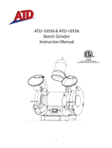
TM400-250

Itm TM400-250 User manual

  • Hello! I've read through the ITM Bench Grinder TM400-250 Operator's Manual and am ready to assist you. This manual provides safety guidelines, assembly and operating instructions with clear diagrams, and it also covers maintenance and troubleshooting. Let me know if you have any questions about your bench grinder!
  • What should I do before making any adjustments to the bench grinder?
    How far from the grinding wheel should the tool rest be set?
    What is the recommended way to clean the bench grinder?
www.itmtools.com.au
Ver: 1.2
TM400-250
OPERATOR’S MANUAL
BENCH GRINDER
INDUSTRIAL
250MM
TM400-250 OPERATOR’S MANUAL
TABLE OF CONTENTS
2
Safety Information ............................................................................................... 3
Package Contents ............................................................................................... 8
Preparation .......................................................................................................... 8
Assembly Instructions .......................................................................................... 9
Operating Instructions ........................................................................................ 11
Care and Maintenance ....................................................................................... 12
Troubleshooting .................................................................................................. 13
Replacement Parts List ...................................................................................... 14
LIMITED WARRANTY
Industrial Tool & Machinery Sales (hereinafter referred to as ITMS) will, within twelve (12)
months from the original date of purchase, repair or replace any goods found to be defective
in materials or workmanship.
This warranty is void if the item has been damaged by accident, neglect, improper service or
other causes not arising out of defects in materials or workmanship. This warranty does not
apply to machines and/or components which have been altered, changed, or modified in any
way, or subjected to overloading or use beyond recommended capacities and specifications.
Worn componentry due to normal wear and tear is not a warranty claim. Goods returned
defective shall be returned prepaid freight to ITMS or agreed repair agent, which shall be the
buyer’s sole and exclusive remedy for defective goods. ITMS accepts no additional liability
pursuant to this guarantee for the costs of travelling or transportation of the product or parts to
and from ITMS or the service agent or dealer, such costs are not included in this warranty.
Our goods come with guarantees which cannot be excluded under the Australian Consumer
Law. You are entitled to replacement or refund for a major failure and to compensation
for other reasonably foreseeable loss or damage. You are also entitled to have the goods
repaired or replaced if the goods fail to be of acceptable quality and the failure does not
amount to a major failure.
THE MANUFACTURER RESERVES THE RIGHT TO MAKE IMPROVEMENTS AND
MODIFICATIONS TO DESIGN WITHOUT PRIOR NOTICE.
PRODUCTS IMPORTED AND DISTRIBUTED NATIONALLY BY:
INDUSTRIAL TOOL & MACHINERY SALES
18 BUSINESS ST, YATALA QLD 4207
T: 07 3287 1114 E: [email protected]
F: 07 3287 1115 W: www.itmtools.com.au
TRADEMASTER
Magnetic Base Drilling Machines
Tools and Machinery
AIR
Warranty .............................................................................................................................. 2
Safety Information ............................................................................................................... 3
Parts Diagram...................................................................................................................... 4
Parts List.............................................................................................................................. 5
Safety Rules ........................................................................................................................ 6
Wheel Dressing ................................................................................................................... 8
Cleaning .............................................................................................................................. 8
Getting Started .................................................................................................................... 9
Troubleshooting ................................................................................................................... 10
2www.itmtools.com.au
TM400-250 OPERATOR’S MANUAL
3
SPECIFICATIONS
1/2 IN.
7,000 RPM +/- 10%
500 FT.-LBS.
6.5 CFM
1/4 IN. NPT
3/8 IN.
90 PSI
COMPONENT
SQUARE DRIVE
FREE SPEED
MAXIMUM TORQUE
AVERAGE AIR CONSUMPTION
AIR INLET
AIR HOSE
WORKING PRESSURE
PRODUCT SPECIFICATIONS
SAFETY INFORMATION
Please read and understand this entire manual before attempting to assemble, operate
or install the product.
Improper operation or maintenance of this product could result in serious injury and
property damage. Read and understand all warnings and operation instructions
before using this equipment. When using air tools, basic safety precautions should
always be followed to reduce the risk of personal injury.
WARNING
Some dust created by power sanding, sawing, grinding, drilling and other related
activities contains chemicals known to the State of California to cause cancer, birth
defects or other reproductive harm. A listing of chemicals can be obtained from
www.oehha.ca.gov under proposition 65. Some examples of these chemicals are:
Lead from lead-based paints
Crystalline silica from bricks, cement and other masonry products
Arsenic and chromium from chemically-treated lumber
Users of these tools should review the chemical composition of the work surface
and any products in conjunction with the operation of these tools for any such
chemicals prior to engaging in any activity that creates dust and/or microscopic
particles.
Users should obtain the material safety data sheets from all identified chemicals,
either from the manufacturer or their employer, and proceed to study, understand,
and follow all instructions and warnings for exposure to such chemicals. Your risk
from these exposures varies, depending on how often you do this type of work.
To reduce your exposure to these chemicals, work in a well-ventilated area, and
work with approved safety equipment, such as those dust masks that are specially
designed to filter out microscopic particles.
WARNING
COMPONENT SPECIFICATIONS
Voltage 240V AC
Motor power 900 Watts
No load speed 2,980 rpm
Spindle thread M16 x 2.0mm
Wheel size 250 x 25mm
Grinding wheels 36# (coarse) and 60# (medium)
Please read and understand this entire manual before attempting to operate the product.
Protective
eye shields
Mounting holesOn / Off switch
Adjustable tool rests
3
www.itmtools.com.au
TM400-250 OPERATOR’S MANUAL
PARTS DIAGRAM
4www.itmtools.com.au
TM400-250 OPERATOR’S MANUAL
PARTS LIST
DIA. NO DESCRIPTION SPEC. QTY DIA. NO DESCRIPTION SPEC. QTY
1 Philips screw M5x62 629 Capacitor support 1
2 Spring washer D5 6 30 Hex bolt with spring
washer M8x25 2
3 Left wheel cover 1 31 Bafe 1
4 I type Hex nut M16-Left 1 32 Rubber foot 4
5 Flange 4 33 Philips screw with big
at washer M5x20 4
6 Bushing 2 34 Hex nut M8 1
7 Stone wheel 36# 250x25x20 1 35 Lock nut M5x15 1
8Philips screw with
spring washer M6x18 6 36 Right wheel inner
guard 1
9Left wheel inner
guard 1 37 Stone wheel 60# 250x25x20 1
10 Philips screw with
spring washer M6x25 8 38 Hex nut M16-Right 1
11 End cap 2 39 Right wheel cover 1
12 Bearing 6205RS 2 40 Moveable work rest
knob M6x17 2
13 Spring washer Ø52 1 41 Fixed work rest knob M8x12 2
14 Rotor 1 42 Right moveable work
rest 1
15 Power cord with
plug 1 43 Flat washer D8 2
16 Stator 1 44 Right xed work rest 1
17 Wave spring washer D4 1 45 Left moveable work
rest 1
18
Philips screw with
at and spring
washer
M4x8 2 46 Left xed work rest 1
19 Wire bushing 1 47 Eyeshield bracket 2
20 Base 1 48 Eyeshield 2
21 Philip screw M4x12 6 49 Eyeshield mounting rod 2
22 Cord press clip 1 50 Left spark reector 1
23 Philip screw M5x8 4 51 Eyeshield mounting rod
Locked knob M6 2
24 Strain relief 1 52 Hex nut M4 4
25 Cord clip plate 1 53 Hex bolt M6x18 2
26 Swich cover 1 54 Philips screw with
spring washer M5x8 4
27 NVR Swich KJD20 1 55 Right spark reector 1
28 Capacitor 1
5
www.itmtools.com.au
TM400-250 OPERATOR’S MANUAL
WARNING! Read all instructions. Failure to follow all instructions listed below may result in electric shock,
fire and/or serious injury. The term “power tool” in all of the warnings listed below refers to your mains-
operated (corded) power tool or battery-operated (cordless) power tool.
SAVE THESE INSTRUCTIONS
Work Area
a. Keep work area clean and well lit. Cluttered and dark areas invite accidents.
b. Do not operate power tools in explosive atmospheres, such as in the presence of flammable liquids,
gases or dust. Power tools create sparks which may ignite the dust or fumes.
c. Keep children and bystanders away while operating a power tool. Distractions can cause you to lose
control.
Electrical Safety
a. Power tool plugs must match the outlet. Never modify the plug in any way. Do not use any adapter
plugs with earthed (grounded) power tools. Unmodified plugs and matching outlets will reduce risk of
electric shock.
b. Avoid body contact with earthed or grounded surfaces such as pipes, radiators, ranges and
refrigerators. There is an increased risk of electric shock if your body is earthed or grounded.
c. Do not expose power tools to rain or wet conditions. Water entering a power tool will increase the
risk of electric shock.
d. Do not abuse the cord. Never use the cord for carrying, pulling or unplugging the power tool. Keep
cord away from heat, oil, sharp edges or moving parts. Damaged or entangled cords increase the
risk of electric shock.
e. When operating a power tool outdoors, use an extension cord suitable for outdoor use. Use of a
cord suitable for outdoor use reduces the risk of electric shock.
Personal Safety
a. Stay alert, watch what you are doing and use common sense when operating a power tool. Do
not use a power tool while you are tired or under the influence of drugs, alcohol or medication. A
moment of inattention while operating power tools may result in serious personal injury.
b. Use safety equipment. Always wear eye protection. Safety equipment such as dust mask, non-skid
safety shoes, hard hat, or hearing protection used for appropriate conditions will reduce personal
injuries.
c. Avoid accidental starting. Ensure the switch is in the off-position before plugging in. Carrying
power tools with your finger on the switch or plugging in power tools that have the switch on invites
accidents.
d. Remove any adjusting key or wrench before turning the power tool on. A wrench or a key left
attached to a rotating part of the power tool may result in personal injury.
e. Do not overreach. Keep proper footing and balance at all times. This enables better control of the
power tool in unexpected situations.
f. Dress properly. Do not wear loose clothing or jewellery. Keep your hair, clothing and gloves away
from moving parts. Loose clothes, jewellery or long hair can be caught in moving parts.
GENERAL SAFETY RULES FOR OPERATION
6www.itmtools.com.au
TM400-250 OPERATOR’S MANUAL
Power tool use and care
a. Do not force the power tool. Use the correct power tool for your application. The correct power tool
will do the job better and safer at the rate for which it was designed.
b. Do not use the power tool if the switch does not turn it on and off. Any power tool that cannot be
controlled with the switch is dangerous and must be repaired.
c. Disconnect the plug from the power source before making any adjustments, changing accessories,
or storing power tools. Such preventive safety measures reduce the risk of starting the power tool
accidentally.
d. Store idle power tools out of the reach of children and do not allow persons unfamiliar with the power
tool or these instructions to operate the power tool. Power tools are dangerous in the hands of
untrained users.
e. Maintain power tools. Check for misalignment or binding of moving parts, breakage of parts and any
other condition that may affect the power tools operation. If damaged, have the power tool repaired
before use. Many accidents are caused by poorly maintained power tools.
f. Keep cutting tools sharp and clean. Properly maintained cutting tools with sharp cutting edges are
less likely to bind and are easier to control.
g. Use the power tool, accessories and tool bits etc., in accordance with these instructions and in the
manner intended for the particular type of power tool, taking into account the working conditions and
the work to be performed. Use of the power tool for operations different from intended could result in
a hazardous situation.
Service
a. Have your power tool serviced by a qualified repair person using only identical replacement parts.
This will ensure that the safety of the power tool is maintained.
ADDITIONAL SAFETY RULES FOR BENCH GRINDERS
a. Ensure that the bench grinder is disconnected from the mains supply when not in use, before
servicing or making adjustments and when changing accessories such as grinding wheels.
b. Always use the correct type of grinding wheel for the type of operation to be carried out and the
material being machined. Do not use a grinding wheel as a cutting disc.
c. Only use grinding wheels that are in good condition. This will improve grinding and reduce the load
on the machine ensuring a longer life of the grinding wheel and the machine.
d. Never use damaged grinding wheels. Grinding wheels that are cracked, chipped or worn could
shatter causing injury to the operator and bystanders and damage to the machine.
e. Do not use grinding wheels that are larger than specified, only use grinding wheels that are rated for
the machine. The rotational speed shown on the grinding wheel should always be HIGHER than the
rotational speed of the machine.
f. Always fit the blotter or paper washers on either side of the grinding wheel if not already fitted to the
grinding wheel.
g. When fitting a new wheel ensure blotter or paper washers are in place, fit concave side of washers
to face the wheel and tighten the lock nut firmly.
h. Do not over tighten (over tightening can crack a grinding wheel).
i. Do not attempt to modify the machine or its accessories in any way.
j. Do not use excessive force on the grinding wheel. Only use gradual pressure as this will reduce the
wear on the bench grinder and grinding wheels and increase its efficiency and operating life.
k. Use approved safety glasses or goggles, face mask and if being used for an extended period wear
ear defenders.
l. Do not start the machine with the work piece in contact with the grinding wheel or before checking
the position of the tool rest.
m. Never apply the work piece to the side of the grinding wheel, this could cause the grinding wheel to
shatter.
7
www.itmtools.com.au
TM400-250 OPERATOR’S MANUAL
MAINTENANCE REQUIRED FREQUENCY
Check power cord Before each use
Inspect wheels for cracks and damage Before each use
Check moving parts for alignment and binding issues Before each use
Dress grinding wheels As needed
Replace grinding wheels As needed
Vacuum dust from the motor housing As needed
General cleaning As needed
WHEEL DRESSING
Wheel dressing is done to renew sharpness or to true up the face of a wheel. A build up of metals and
dirt will become embedded in a wheel as it is used. Use a wheel dressing tool (not supplied) to clean
wheels on a regular basis. In doing so, it will improve the bench grinder’s performance.
NOTE: New wheels may sometimes require dressing to true up their surface.
CLEANING
Use only mild soap and a damp cloth to clean the bench grinder. Never let any liquid get inside the tool.
DO NOT immerse any part of the bench grinder into a liquid.
Service beyond recommended maintenance on this bench grinder should only be performed by an
authorized, qualified technician.
WARNING Ensure the bench grinder is disconnected from the
power supply when performing maintenance tasks
to avoid injury.
!
n. Keep guards in place and in good working order. With the machine disconnected from the mains
supply check that the guards are secure and fitted correctly.
o. Always keep the tool rest as close to the grinding wheel as possible. The gap between the tool rest
and the grinding wheel should be no more than 3mm.
p. Do not attempt to grind objects that are too small to hold safely.
q. Do not use the work piece to slow down the grinding wheel once the machine has been switched off.
r. WARNING! Do not use bench grinders in areas where there is a risk of explosion or fire from
combustible materials, flammable liquids, paint, varnish, petrol etc. flammable gases and dust of an
explosive nature. As a precaution it is recommended that you consult an expert on a suitable fire
extinguisher and its use. The metal particles (sparks) which are produced during grinding are hot
and could ignite any combustible material in the vicinity of the operation.
8www.itmtools.com.au
TM400-250 OPERATOR’S MANUAL
Accessories
The bench grinder is supplied with the following accessories:
2 eye shields with mounting brackets and 2 tool rests
CAUTION. Always ensure that the bench grinder is switched off and plug is removed from the power
point before making any adjustments.
To fit the eye shields locate the nut, screw and washers provided through the slot in the eye shield and
hole on the grinding wheel guard and finger tighten. Position the eye shield so it does not come in to
contact with the grinding wheel. Tighten the nut and screw to secure the eye shield in place.
Attach the tool rests using the bolts and securing knobs provided and adjust to the correct position. The
gap between the tool rest and grinding wheel should be set to 2mm.
Bench Mounting
The Grinder can be secured with screws or nuts and bolts. Locate the mounting holes. The length of
the bolts or screws will depend on the thickness of the bench. Where a steel bench is used, it is best to
mount the grinder on to a board, then attach the board to the bench, this will also minimize vibration.
Switching On And Off
Before connecting to the power supply rotate the wheel by hand to ensure that it is running properly and
free from obstruction. Connect to the mains supply and press the rocker switch to the ON position (l).To
stop the machine simply press the rocker switch to the OFF position (o).
General Inspection
Regularly check that all the fixing screws are tight. They may vibrate loose over time.
GETTING STARTED
9
www.itmtools.com.au
TM400-250 OPERATOR’S MANUAL
SYMPTOM CAUSE CORRECTIVE ACTION
Motor will not start.
1. Low Voltage.
2. Open circuit in motor or loose
connections.
3. Blown fuse or breaker.
4. Not plugged in or switched on
at wall
1. Check power source for proper voltage.
2. Inspect all lead connection on motor for loose or open
connections. (Send for Servicing.)
3. Short circuit. (Send for Servicing.)
4. Improper match between tool and circuit, fuse or breaker.
Motor will not start –
fuses or circuit
breakers tripping or
blowing.
1. Short circuit in line, cord or plug.
2. Short circuit in motor or loose
connections.
3. Incorrect fuses or circuit breakers
in power line
1. Inspect cord or plug for damaged insulation and shorted wires.
2. Inspect all connections on motor for loose or shorted terminals
and/or worn insulation.
3. Install correct fuses or circuit breakers or
switch tool to an appropriately sized circuit.
Motor overheats.
1. Motor overloaded.
2. Extension cord too long and
insufcient gauge (weight).
1. Reduce load on motor.
2. Utilize an extension cord of appropriate gauge and length or plug
tool directly into outlet.
Motor stalls (resulting
in blown fuses or
tripped circuit).
1. Short circuit in motor or loose
connections.
2. Low voltage.
3. Incorrect fuses or circuit breakers
in power line.
4. Motor overload.
1. Inspect connections on motor for loose or shorted terminals or
worn insulation. (Send for Servicing.)
2. Correct low voltage conditions (for example: improper extension
cord length and/or gauge).
3. Install correct fuses or circuit breakers or plug tool into an
appropriate circuit, matched to an appropriate fuse or breaker.
4. Reduce the load on the motor.
Machine slows when
operating. 1. Feed rate too great. 1. Reduce the rate at which the workpiece is fed into the working
area of the tool
Wavy condition on
surface of workpiece
1. Machine vibrating.
2. Workpiece is not being held rmly
3. Wheel face uneven.
4. Wheel is too hard.
1. Ensure machine is securely mounted on a solid surface.
2. Use a holding device to rmly retain the workpiece.
3. Dress the grinding wheel.
4. Use softer wheel, or reduce the feed rate.
Lines on surface of
workpiece.
1. Impurity on surface of wheel.
2. Workpiece not being held tightly
1. Dress the grinding wheel.
2. Try holding the device to more rmly retain
Burning spots or
cracks in the
workpiece.
1. Improper type of grinding wheel.
2. Improper feed rate.
1. Try wheels with softer bond or coarser grit.
2. Slow down the rate at which the workpiece is fed into the wheel.
Wheel dulls quickly, grit
falls off
1. Feed rate is too aggressive.
2. Wheel is soft.
3. Wheel diameter too small.
4. Bad wheel dressing.
5. Defective wheel bonding.
1. Decrease feed rate of workpiece into grinding wheel.
2. Select a grinding wheel with a harder bond of material.
3. Replace wheel.
4. Dress the wheel.
5. DO NOT USE – return wheel to point of purchase
Wheel clogs and
workpiece shows
burn marks.
1. Wheel is too hard.
2. Feed rate is too slow.
3. Bad wheel dressing.
1. Select a grinding wheel with a softer bond of material.
2. Increase the feed rate of the workpiece into the grinding wheel.
3. Dress the wheel.
TROUBLESHOOTING
10 www.itmtools.com.au
/