Page is loading ...

PREMIER
L8542132
Rev. 07/06/00
APRICANCELLO ELETTROMECCANICO
ELECTROMECHANICAL GATE OPENER
ELEKTROMECHANISCHE AUTOMATION FÜR SCHIEBEGITTER
AUTOMATISATION ÉLECTROMÉCANIQUE POUR GRILLES
ABRECANCELA ELECTROMECANICO
ELEKTROMECHANICZNY OTWIERACZ BRAM
Manual istruzioni e catalogo ricambi
Operating instructions and spare parts catalogue
Betriebsanleitung und Ersatzteilliste
Livret d’instructions et catalogue des pieces de rechange
Manual de instrucciones y catálogo de recambios
Książeczka z instrukcjami i katalog części wymiennych
UNIONE NAZIONALE COSTRUTTORI
AUTOMATISMI PER CANCELLI, PORTE
SERRANDE ED AFFINI

2
3
Dichiarazione CE di conformità per macchine
(Direttiva 98/37 CE, Allegato II, parte B)
Divieto di messa in servizio
Fabbricante: Automatismi Benincà SpA.
Indirizzo: Via Capitello, 45 - 36066 Sandrigo (VI) - Italia
Dichiara che: lʼautomazione per cancelli a battente modello:
PREMIER - PREMIER L - PREMIER R -PREMIER 24.
• è costruito per essere incorporato in una macchina o per essere assemblato con altri macchinari per costituire una macchina con-
siderata dalla Direttiva 98/37 CE, come modicata;
• non è dunque conforme in tutti i punti alle disposizioni di questa Direttiva;
• è conforme alle condizioni delle seguenti altre Direttive CE:
Direttiva bassa tensione 73/23/CEE, 93/68/CEE.
Direttiva compatibilità elettromagnetica 89/336/CEE, 93/68/CEE.
e inoltre dichiara che non è consentito mettere in servizio il macchinario no a che la macchina in cui sarà incorporato o di cui diverrà
componente sia stata identicata e ne sia stata dichiarata la conformità alle condizioni della Direttiva 98/37 CE e alla legislazione
nazionale che la traspone, vale a dire no a che il macchinario di cui alla presente dichiarazione non formi un complesso unico con
la macchina nale.
Benincà Luigi, Responsabile legale.
Sandrigo, 05/06/2006.
Declaration by the manufacturer
(Directive 98/37/EEC, Art. 4.2 and Annex II, sub B)
Divieto di messa in servizio
Manufacturer: Automatismi Benincà SpA.
Address: Via Capitello, 45 - 36066 Sandrigo (VI) - Italia
Herewith declares that: the operator for hinged gates model:
PREMIER - PREMIER L - PREMIER R -PREMIER 24.
• is intended to be incorpored into machinery or to be assembled with other machinery to constitute machinery covered by Directive
98/37 EEC, as amended;
• does therefore not in every respect comply with the provisions of this Directive;
• does comply with the provisions of the following other EEC Directives:
Direttiva bassa tensione 73/23/CEE, 93/68/CEE.
Direttiva compatibilità elettromagnetica 89/336/CEE, 93/68/CEE.
and furthermore declares that it is not allowed to put the machinery into service until the machinery into which it is to be incorporated
or of which it is to be a component has been found and declared to be in conformity with the provisions of Directive 98/37/EEC and
with national implementing legislation, i.e. as a whole, including the machinery referred to in this declaration.
Benincà Luigi, Responsabile legale.
Sandrigo, 05/06/2006.

4
5
332
130
112
160
365
650
42
170
115
160
165
Fig.1
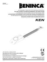
Dimensioni d’ingombro
Overall dimensions
Abmessungen
Dimensions d’encombrement
Dimensiones exteriores
Wymiary gabarytowe
Dati tecnici Technical data Technische Daten
PREMIER PREMIER L PREMIER R PREMIER 24
Alimentazione
Alimentazione motore
Potenza assorbita
Corrente assorbita
Coppia
Classe isolamento mot.
Giri motore
Giri uscita
Peso max. anta
Lunghezza max. anta
Condensatore
Rumorosità
Lubricazione
Grado IP
Temp. funzionamento
Peso
Power supply
Motor feed
Power drawn
Current drawn
Torque
Motor insulation class
Motor r.p.m.
Output rounds
Door leaf max. weight
Door leaf max.
Capacitor
Noise level
Lubrication
IP class
Operating temp.
Weight
Stromversorgung
Motorspeisung
Aufgenomm. Leistung
Aufgenomm. Strom
Drehmoment
Schutzklasse des Mot.
Motorendrehzahl
Drehzahl am Ausgang
Max. Türügelgewicht
Max. Flügellänge
Kondensator
Geräuschentwicklung
Schmierung
IP Grad
Betriebstemperatur
Gewicht
230 Vac
230 Vac
170 W
0,85 A
300 Nm
F
1400 rpm
1,82 rpm.
300 kg
3 m
8 µF
<70 dB (A)
Agip GR MU EP/2
IP54
-20°C/+70°C
13 kg
230 Vac
230 Vac
170 W
0,85 A
300 Nm
F
900 rpm
1,17 rpm.
300 kg
4 m
8µF
<70 dB (A)
Agip GR MU EP/2
IP54
-20°C/+70°C
13 kg
230 Vac
230 Vac
170 W
0,85 A
150 Nm
F
1400 rpm
3,64 rpm.
200 kg
2 m
8µF
<70 dB (A)
Agip GR MU EP/2
IP54
-20°C/+70°C
13 kg
230 Vac
24Vdc
120 W
8 A
260 Nm
Y
1400 rpm
1,82 rpm.
250 kg
2,5m
--
<70dB (A)
Agip GR MU EP/2
IP54
-20°C/+70°C
13 kg
Donnees technique
Datos técnicos
Dane techniczne
PREMIER PREMIER L PREMIER R PREMIER 24
Alimentation
Alimentation moteur
Puissance absorbée
Courant absorbé
Couple
Classe d'isolement
Régime
N. de tours en sortie
Poids max. porte
Longueur max. porte
Condensateur
Bruit
Lubrication
Degré IP
Temp. fonctionnement
Poids
Alimentación
Alimentación del motor
Consumo de potencia
Consumo de corriente
Par
Clase aislamiento mot.
Revoluciones motor
Revoluciones salida
Peso máx. hoja
Longitud máx. hoja
Condensador
Ruido
Lubricación
Índice IP
Temp. de funcionamiento
Peso
Zasilanie
Zasilanie silnika
Natężenie
Pobór mocy
Moment obrotowy
Klasa izolacji silnika
Obroty silnika
Obroty wyjściowe
Ciężar max. skrzydła
Dł. max. skrzydła
Kondensator
Max. halas
Smarowanie
Stopień IP
Temp. podczas pracy
Ciężar
230 Vac
230 Vac
170 W
0,85 A
300 Nm
F
1400 rpm
1,82 rpm.
300 kg
3 m
8 µF
<70 dB (A)
Agip GR MU EP/2
IP54
-20°C/+70°C
13 kg
230 Vac
230 Vac
170 W
0,85 A
300 Nm
F
900 rpm
1,17 rpm.
300 kg
4 m
8 µF
<70 dB (A)
Agip GR MU EP/2
IP54
-20°C/+70°C
13 kg
230 Vac
230 Vac
170 W
0,85 A
150 Nm
F
1400 rpm
3,64 rpm.
200 kg
2 m
8µF
<70 dB (A)
Agip GR MU EP/2
IP54
-20°C/+70°C
13 kg
230 Vac
24Vdc
120 W
8 A
260 Nm
Y
1400 rpm
1,82 rpm.
250 kg
2,5m
--
<70dB (A)
Agip GR MU EP/2
IP54
-20°C/+70°C
13 kg

6
7
Fig.4
F
Sblocco a lo art. DU.MS45.
Wire release art. DU.MS45.
Freigabe über Draht DU.MS45.
Déblocage à l art. DU.MS45.
Desbloqueo por cable art. DU.MS45
Odblokowanie na linkę art. DU.MS45.
Vite M8x10 UNI 5739.
Screw M8x10 UNI 5739.
Schraube M8x10 UNI 5739.
Vis M8x10 UNI 5739.
Tornillo M8x10 UNI 5739.
Sruba M8x10 UNI 5739
Rosetta per M8 DIN 6798E.
Washer M8 DIN 6798E.
Scheibe M8 DIN 6798E.
Rondelle M8 DIN 6798E.
Arandela para M8 DIN 6798E.
Podkładka dla M8 DIN 6798E
Maniglia con piastra.
Handle with plate.
Handgriff mit Platte.
Manette avec plaque.
Desbloqueo con placa.
Uchwyt z płytą
Morsetto.
Clamp.
Klammer.
Étau.
Perrillo.
Zacisk
Registro.
Register.
Regulierung.
Réglage.
Registro.
Rejestr
Rosetta 9x24 UNI 6593.
Washer 9x24 UNI 6593.
Scheibe 9x24 UNI 6593.
Rondelle 9x24 UNI 6593.
Arandela 9x24 UNI 6593.
Podkładka 9x24 UNI 6593
Carter.
Cover.
Gehäuse.
Couvercle.
Carter.
Karter
L
G
K
C
Vite M6x10 UNI 5927
Screw M6x10 UNI 5927
Schraube M6x10 UNI 5927
Vis M6x10 UNI 5927
Tornillo M6x10 UNI 5927
Sruba M6x10 UNI 5927
Staffa
Bracket
Winkel
Gousset
Placa de anclaje
Strzemiączko
Rosetta Ø6.6x18 UNI 6953
Washer Ø6.6x18 UNI 6953
Scheibe Ø6.6x18 UNI 6953
Rondelle Ø6.6x18 UNI 6953
Arandela Ø6.6x18 UNI 6953
Podkładka Ø6.6x18 UNI 6953
Vite M6x16 UNI 5931
Screw M6x16 UNI 5931
Schraube M6x16 UNI 5931
Vis M6x16 UNI 5931
Tornillo M6x16 UNI 5931
Sruba M6x16 UNI 5931
Biella
Connecting rod
Pleustange
Bielle
Biella
Korbowód
Perno per biella
Pin for connecting rod
Stift
Pivot pour bielle
Clavija para biella
Sworzeń korbowodu
Leva
Lever
Hebel
Levier
Leva
Dźwignia
Art. DU.E2

8
9
Fig.5
Fig.6
50
A B
150
200
250
300
883
851
828
800
846
277
181
11
7
32
28
429
466
475
469
468
C D
* È necessario che all’atto dell’apertura, il braccio abbia almeno
lo spazio segnalato.
* When opening it’s necessary that the arm has at least the
signaled space.
* Beim Öffnen muß der Arm wenigstens den angegebenen Raum
haben.
* Il est nécessaire que lors de l’ouverture, le bras ait au moins
l’espace signalé.
* Es necesario que en el acto de apertura, el brazo tenga al menos
el espacio señalado.
* Konieczne jst, żeby podczas otwierania skrzydło miało do
dyspozycji zaznaczony obszar manewru.
Apertura 130° max.
Max 130° opening.
Anbringung zum Öffnen, höchstens 130°
Ouverture max. 130°
Apertura 130° max.
Maks otwarcie 130°
D
B
C
112
A
100
20
40
100
*160
*181
237
60
775

10
11
4
1
2
RG 58
6
3x1,5 min
230 V
5
2
1
2x1,5
2x1
2x1
A
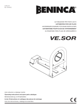
N.B.: Tenere separati i cavi di potenza da quelli ausiliari.
N.B.: The power cables must be kept separated from the auxiliary cables.
Wichtig: Leistungskabel von Hilfskabeln getrennt halten.
N.B.: Séparer les câbles de puissance des câbles auxiliaires.
N.B.: Tener separados los cables de potencia de los auxiliares.
Uwaga: należy trzymać w oddali przewody zasilania od przewodów pomocniczych.
Legenda:
1 Motoriduttore PREMIER
2 Fotocellule FTC/FTM
3 Selettore a chiave CH (da esterno) o tastiera digitale
4 Lampeggiante LAMP
5 Antenna AW
6 Centrale elettronica.
Legenda:
1 Motoreducer PREMIER
2 Photo-electric cells FTC/FTM
3 Key selector CH (external) or digital keyboard
4 Flash-light LAMP
5 Antenna AW
6 Electronic board.
Zeichenerklärung:
1 Getriebemotor PEMIERE
2 Fotozelle FTC/FTM
3 Schlüssel-Selektor CH (außenliegend) oder Digital-Tastatur
4 Blinker LAMP
5 Antenne AW
6 Elektroschrank.
Légende:
1 Moteur-réducteur PREMIER
2 Photocellule FTC/FTM
3 Selecteur à clé CH (d’extérieur) ou clavier digital
4 Clignotant LAMP
5 Antenne AW
6 Centrale électronique.
Leyenda:
1 Motorreductor PREMIER
2 Fotocélulas FTC/FTM
3 Selectores a llave CH (de supercie).
4 Relampagueador LAMP.
5 AntenaAW.
6 Central electrónica.
Objaśnienia:
1 Siłownik PREMIER
2 Fotokomórki FTC/FTM
3 Przełącznik kluczowy CH (zewnętrzny) lub panel z przyciskami
4 Światło migające LAMP
5 Antena AW
6 Centralka elektroniczna
A
4x1
A
PREMIER / L / R 4x1,5mm
2
PREMIER 24 2x1,5mm
2
+ 3x0,5mm
2

12
13
Warning
• Before installation, carefully read the instructions hereunder.
• It is strictly forbidden to use the item PREMIER for applications other than the intended uses described in
these instructions.
• Instruct the user on how to use the system.
Introduction
Thank you for choosing our PREMIER ratiomotor. All items in the wide Benincà production range are the
result of twenty-years’ experience in the automatism sector and of continuous research for new materials
and advanced technologies. We are, therefore, in the position to offer higly reliable products that due to their
power, effectiveness and useful life, fully satisfy the nal user’s requirements.
All our products are manufactured to the existing standard and are covered by warranty. Possible injury to
people or accidents caused by defects in construction are covered by a civil liability policy drawn up with one
of the major insurance companies.
General notes
For a good operation of the automatic system the door to be automated must feature the following character-
istics:
• Rugged and stiff door leaves.
• Efcient hinges.
• The door leaves should be moved by hand without any friction for the entire stroke.
• The doors should be complete with a catch in the closing phase.
In the negative, replace the faulty parts. Reliability and safety of the automatic system depend on the gate
structure.
General features
This automatism has been designed to automatize doors, the dimensions of which do not allow to use tra-
ditional actuators.
It is equipped with an articulated arm and with a limit switch, (PREMIER). The operations are smooth and noi-
seless. It is easy to be assembled and, thanks to its pleasant design, it meets the most demanding needs.
The emergency block is simple and safe thanks to the lever with personalised key.
Connections
PREMIER/PREMIER L / PREMIER R:
Brown Motor phase and capacitor
Grey or Light blue Common
Black Motor phase and capacitor
Yellow/Green Earth - compulsory pursuant to regulations in force
The limit switch contacts are connected in series to the two motor phases. If, after an opening control, the
motor starts the closing movement, it is sufcient to reverse the brown wire with the black one in the control
unit.
PREMIER 24:
Red Motor +
Black Motor -
Carry out the limit switch connections to the control unit.
If, after an opening control, the motor starts the closing movement, it is sufcient to reverse the red wire with
the black one in the control unit.
As regards the torque adjustments and the operating modes, please read instructions given in the control
unit manual.
To adjust the limit switches (Fig. 3)
The PREMIER unit is equipped with built-in limit switches for both opening and closing phases. Proceed as
follows:
• Release the actuator (see paragraph “Release by hand”)
• Remove the cover M from the release lever L.
• Loosen the screw V1 and remove the release lever L.
• Loosen the screws V2 and remove the cover.

14
15
• Close the gate until it touches the stopper.
• Loosen the tting screw of the cam and adjust the cam until triggering of the micro-switch.
• The same operation should be carried out with the other cam, with completely open gate.
• Reset the automatic operation and check the correct positioning of the cams by opening and closing the
gate for a few times.
• Tighten the xing screws of the cams.
Note:
The PREMIER /R/L (230Vac) models feature a thrust of some seconds on the stoppers without damaging
the gear motor. If required, it is therefore possible to select the timed operation, thus excluding the limit
switches.
In the PREMIER 24 model, cams should be adjusted and limit switches should be connected to the control
unit.
Release by hand
As regards the manual operation, should a power failure occur two solutions are available for the PREMIER
unit :
Release from inside (Fig. 3)
• Insert the customised key C, and turn it clockwise.
• Turn the release lever L for at least 90° clockwise.
• At this point, the reduction gear is released and the gate can be moved by had.
• To reset the normal operation, move the lever L to the original position and turn key C anti-clockwise. When
the unit is powered again, the normal operating mode will be reset with the rst movement of the gate.
Internal-external release with cord (Item DU.MS45) (Fig. 4 - optional)
• Insert the steel cable C on lever L.
• Introduce the sheath G with the cable gland K until it reaches the hole F.
• Fit the steel cable C in the handle, according to Fig. 4.
• Turn the handle to release.
• By turning the handle again, the rst operation will reset the normal operating mode.
Applications
Application suitable to max 90° opening inward (g. 5.
Application suitable to max 130° opening (g. 6).
P.N. When opening it’s necessary that the arm has at least the signaled space.
Application suitable to opening to the outside (gg. 7 - 8).
CAUTION
The civil liability policy, which covers possible injuries to people or accidents caused by defects in construc-
tion, requires the system to be to existing standard and to use original Benincà accessories.

26
27
Safety rules
• Do not stand in the movement area of the door.
• Do not let children play with controls and near the door.
• Should operating faults occur, do not attempt to repair the fault but call a qualied technician.
Manual and emergency operation
To manually open or close the door in case of power failure or faults, two solutions are possible:
• Built-in release
• Insert the customised key C, and turn it clockwise.
• Turn the release lever L for at least 90° clockwise.
• At this point, the reduction gear is released and the gate can be moved by had.
• To reset the normal operation, move the lever L to the original position and turn key C anti-clockwise. When
the unit is powered again, the normal operating mode will be reset with the rst movement of the gate.
• Rope external release: optional
It is available for tting to external wall or with accessory to be mounted ush.
Maintenance
• Every month check the good operation of the emergency manual release.
• It is mandatory not to carry out extraordinary maintenance or repairs as accidents may be caused.
These operations must be carried out by qualied personnel only.
• The operator is maintenance free but it is necessary to check periodically if the safety devices and the other
components of the automation system work properly. Wear and tear of some components could cause
dangers.
Waste disposal
If the product must be dismantled, it must be disposed according to regulations in force regarding the dif-
ferentiated waste disposal and the recycling of components (metals, plastics, electric cables, etc..). For this
operation it is advisable to call your installer or a specialised company.
Warning
All Benincá products are covered by insurance policy for any possible damages to objects and persons
caused by construction faults under condition that the entire system be marked CE and only Benincá parts
be used.
User’s handbook
PREMIER
Customized key C
Lever L
/