Pro-Ject Audio Systems Signature 12 User manual
- Category
- Turntable
- Type
- User manual

INSTRUCTIONS FOR USE
Pro-Ject SIGNATURE

Pro-Ject SIGNATURE
Your contribution to environmental protection
Disposal of packaging material:
The packaging protects the device against damage during transport. Packaging materials have been selected
with environmental aspects and possibilities of their liquidation and they are recyclable.
Disposal of old device:
Old devices must be collected separately in order to optimise the recovery and recycling of the materials they
contain and reduce the impact on human health and the environment. Consumers should contact their local
authority or retailer for information concerning the correct disposal of their old device.
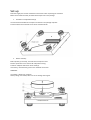
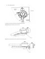
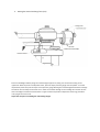
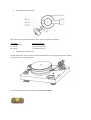
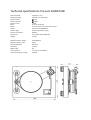
Controls, features and connections
1. Platter
2. Platter shaft
3. Drive pulley
4. Drive belt
5. Idler pulley shaft
6. Idler pulley
7. Platter belt
8. Transport screws
9. Adjustable feet
10. Tonearm
11. Azimuth set screw
12. VTA locking screw
13. VTA set screw
14. Mounting distance adjusting screw
15. Locking screw for mounting distance adjusting
16. Power supply
17. Control panel
18. ON/OFF switch
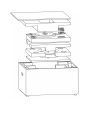
The device is transported in a partially disassembled to prevent damage sensitive parts.
Check the packaging and the device immediately if they were not damaged during transport.
Damaged devices not operate.
Compare the data for electrical connection on the plate with the data network.
These data must match in order to avoid damage of the turntable.

Set-up
Read thoroughly the manual and follow all instructions after unpacking the turntable.
Make the turntable assembly of distributed components in the package.
1. Installation of adjustable feet (9)
The feet are disassembled for transport and stored in the package of platter.
Screw the feet into the thread inserts of the turntable plinth.
2. Platter assembly
Before platter (1) assembly, unscrew three transport screws.
Remove protective covers from shaft and platter bearing.
Check for adequate lubrication of the shaft (2).
If necessary, lubricate with grease in the attached accessories.
WARNING:
The platter is floating on magnets.
When putting on the shaft, take care not to damage the magnet.

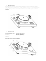
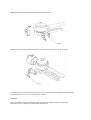
3. Idler pulley assembly
Idler pulley consists of two parts. One is powered by the motor units and one is floated on the magnetic
cushion. Both parts form a whole stored on a common shaft. Before installing this kit remove the covers from
the shaft and bearing. Check for adequate lubrication. If necessary, lubricate with grease in the attached
accessories.
4. Drive belt assembly
Drive belts (4) fitting in order: front drive - idler pulley (3)
rear drive - idler pulley (3)
Drive belt (7) idler pulley (3) - platter (1)
WARNING:
Don’t stretch belts too much to avoid damage.

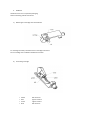
5. Headshell
Headshell is stored in a separated packaging.
When assembling, follow instructions:
a) Mounting the cartridge into the headshell:
For cartridge assembly use fasteners from cartridge accessories.
Fix the cartridge in the middle of headshell oval holes.
b) Connecting cartridge
• White left channel L+
• Red right channel R+
• Green right channel R-
• Blue left channel L-

c) Headshell assembly
Plug headshell into the front of the tube. Connector pin must be oriented into the groove. Fixing nut tighten on
the tonearm tube properly.
d) Counterweight assembly
Put on counterweight on the support rod. Tighten the locking screw gradually and watch than the shaft entry
into thread groove. Then tighten the locking screw. Correction of counterweight’s weight is provided by
additional counterweight is also tighten by the set screw.

Setting range of counterweight:
1. Counterweight without additional counterweight
This setting balance cartridge with weight 4.5 – 8 gr.
2. Counterweight with additional counterweight with dimensions Ø15mm, length 30mm.
This setting balance cartridge with weight 8 – 15 gr.
3. Counterweight with additional counterweight with dimensions Ø15mm, length 45mm.
This setting balance cartridge with weight 15 – 23 gr.
Please note that the maximum visible part of this additional counterweight is 21mm.

e) Assembly of removable tonearm part to the turntable
Detachable tonearm part, which we already prepared, carefully put to it’s place.
Insert output connector carefully into socket in housing. Positioning pin must be directed to cartridge
counterweight. After insertion the connector into socket, lock the connector with fixing nut.
f) Tonearm output connection
Attached signal cabel plug to tonearm 5-PIN connector, which is located on the bottom side of the turntable.
Keep the right positioning.

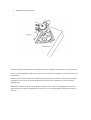
g) Anti-skating assembly
Assembly of anti-skating is described in the following four steps:
Step 1: Mounting the thread on the hook screw
Step 2: Put the thread on the correct position in the tonearm groove

Step 3: Mounting the anti-skating sliding mechanism on the shaft
Step 4: Positioning of the sliding mechanism. Eye of the thread insert on the pin in the groove.
When the tonearm is over the first outer groove of the record, the anti-skating thread must be already
tensioned, when it’s in the end, it must be still on tension.
WARNING:
When the thread isn’t tensioned at the beginning, at the end already falling on the other side.
Be careful, there is a danger to rip off thread by tensile force.

OPERATING AND CALIBRATION
1. Cartridge setting
Effective length = 304.8mm (12”)
(distance between needle of the cartridge and the vertical rotation axis of the tonearm)
Mounting distance= 291.6mm
(distance between spindle and the vertical rotation axis of the tonearm)
Outer nullpoint: r= 62,5mm
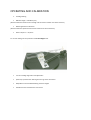
For correct setting use the protractor or Pro-Ject Align It tool.
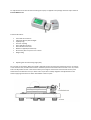
Tool for cartridge alignment and adjustment
Special slip-proof tool for defining the turning centre of tonearm
Adaptable to accommodate differing tonearm lengths
Suitable for other manufacturer’s tonearms

Setting the position of cartridge in the headshell:
For setting the correct position of cartridge in headshell grooves we designed for you small tool from
transparent plexiglass. Please note that this tool is only for headshell from Pro-Ject SIGNATURE tonearm.
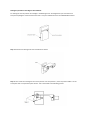
Step 1: Place the tool with groove to the headshell as shown.
Step 2: Then move the cartridge to the correct position. Correct position is, if the top of the needle is in the
same plane like as comparative plane of tool. This is illustrated in the following picture.

2. Setting the vertical tracking force (VTF)
Place counterweight halfway along the counterweight support rod, being sure to have the locking screw
uppermost. With the power of and platter static, place the stylus pressure gauge onto the platter. To set the
required VTF place the tip of the stylus on the pressure gauge. Moving the counterweight towards the cartridge
will reduce VTF and away will increase VTF. In order to avoid the damage oh the cartridge be sure that all time
all the cartridges movements must be done in upper tonearm lift position. Repeat the measuring procedure
until you get the correct VTF.
Adjust the VTF prior to installing the anti-skating weight.

For adjustment and control of vertical tracking force (VTF) is supplied in the package electronic stylus balance
Pro-Ject Meaure IT II
Product information:
Case made of aluminium
4 digit LCD-Display with backlight
Capacity 0-5g
Variance ± 0,002g
Auto calibration function
Auto off after 60 seconds
Batteries supplied (teo AAA cells)
Dimensions (W x H x D) 122 x 25 x 55mm
Weight 170g
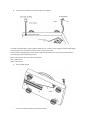
3. Adjusting the vertical tracking angle (VTA)
Put a record on the platter. When the needle is lowered into the record groove and the tonearm is not resting
on the tonearm rest, the tube of the tonearm should be parallel to the surface of the record. If it is not, loosen
both VTA adjustment screws in the tonearm base just enough to allow vertical movement of the arm pillar
without force and slide the arm up or down until it is parallel. Carefully retighten VTA adjustment screws
without applying excessive force which would deform the arm pillar.

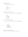
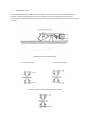
4. Adjusting the azimuth
The cartridge needle must be vertical in the record groove in order to trace the groove wall modulations
correctly. A small azimuth adjusting screw on the headshell allows incorrect azimuth to be corrected.
Correct position can be checked from the front view, preferably with needle placed on a mirror which is placed
on platter.
Examples of incorrect azimuth setup:
Too much left angle: Too much right angle:
The correct position is 100% perpendicular to the record.

5. Mounting distance adjustment
Loosen the locking nut allows the linear shifting of the tonearm. Adjust correct distance by using of the scale.
The correct mounting distance 304.8 mm on the scale is valid only if the cartridge is in the correct position on
the headshell.
However there are exist very special and different cartridge types which makes a correct mounting distance
impossible. In this case you can change the distance of the arm easily and allow you to use all available
cartridge types.
Additional this feature allows you to use different alignment tools. There are existing different versions of
alignment tools for setting and optimization of null points. You can get with different settings small sound
variations.

6. Anti-skating force adjustment
With the anti-skating slider adjust the position of the arm weight at 45 degrees.
Downforce: Anti-skating groove:
Lower than 13mN 1
st
from bearing rings
13 - 18 mN 2
nd
from bearing rings
18 - 25mN 3
rd
from bearing ring
7. Adjusting the turntable plane
Put the spirit level on the top of the turntable. With feet that are screw-type balance the turntable.
Control the plane in several directions.
For optimum positioning of a turntable is supplied Pro-Ject LEVEL IT

8. Connect the turntable to the power supply and amplifier
Turntable is supplied with a power supply suitable for your country’s mains supply. Check the label before
connecting to ensure compliance with the mains rating in your house.
Connect the low voltage plug from the power supply to the socket on the rear of the turntable before
connecting the power supply to the mains.
Signal cabel connect with your phono preamplifier
Red – right channel
White – left channel
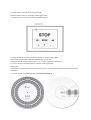
9. The turntable control
• Turn on the switch located in the bottom of plinth

Turntable control is performed by the touch screen.
After turning the switch on, the display shows logo Pro-Ject.
Touching the screen you can control the turntable functions.
Touching on field 33 or 45 select the desired speed. The display shows „WAIT“ .
After reaching rated speed is displayed selected value 33,3 or 45,1 .
Rated speed can be correct by touching the + or –, which changes the value by 0.1 %
Turn off or pause the recording perform is done by touching the STOP.
Please note :
The actual shown speed must not be as the speed in reality. A lot of different possible physical variations may
influence it.
For correct control of turntable speed is supplied Pro-Ject Strobe IT

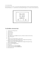
Time and date setting
By touching the screen on the „T“ go to time and date setting window. Touch the mark with altered number
and correct value by + or -. The set values can be saved by touching the „S“. To return to control touch the „C“.
Turntable accessories:
1. 2 pieces of anti-skating thread
2. Centering ring
3. Allen key 1.6mm
4. Allen key 2mm
5. Allen key 5mm
6. Signal cabel Connect IT PHONO 5P-C (123 cm, already connected in the tonearm)
7. White cotton gloves
8. Cloth
9. Additional counterweight Ø15mm, length 30mm.
(together with the basic counterweight balance cartridge with weight 8-15 gr)
10. Additional counterweight Ø15mm, length 45mm.
(together with the basic counterweight balance cartridge with weight 15-23 gr)
11. Spirit level Pro-Ject Level IT
12. Tool for correct cartridge assembly
13. Record puck
14. Cartridge alignment tool Pro-Ject Align IT
15. Electronic stylus balance Pro-Ject Measure IT
16. Instructions for use
Page is loading ...
Page is loading ...
Page is loading ...
-
 1
1
-
 2
2
-
 3
3
-
 4
4
-
 5
5
-
 6
6
-
 7
7
-
 8
8
-
 9
9
-
 10
10
-
 11
11
-
 12
12
-
 13
13
-
 14
14
-
 15
15
-
 16
16
-
 17
17
-
 18
18
-
 19
19
-
 20
20
-
 21
21
-
 22
22
-
 23
23


Pro-Ject Audio Systems Signature 12 User manual
- Category
- Turntable
- Type
- User manual
Ask a question and I''ll find the answer in the document
Finding information in a document is now easier with AI
Related papers
-
Pro-Ject Signature 10 User manual
-
Pro-Ject Audio Systems Xtension 12 User manual
-
Pro-Ject THE CLASSIC User manual
-
-
-
Pro-Ject X1 User manual
-
-
Pro-Ject Essential III Bluetooth User manual
-
-
Other documents
-
Pro-Ject Signature 12 User manual
-
Audio-Technica AT-LPW30 User manual
-
Dual CS 429 User manual
-
Pro-Ject Ortofon Century User manual
-
-
Pro-Ject The Classic Evo User manual
-
-
argon audio TT Owner's manual
-
Pro-Ject Xtension 9 Evolution User manual
-