
M68PCBUG11/D
REV 3
December 1996
M68HC11 PCbug11
USER'S MANUAL
© 1991, 1992, by MOTOROLA, INC.
Frees
cale Semiconductor,
I
Freescale Semiconductor, Inc.
For More Information On This Product,
Go to: www.freescale.com
nc...

Motorola reserves the right to make changes without further notice to any products herein to
improve reliability, function, or design. Motorola does not assume any liability arising out of the
application or use of any product or circuit described herein; neither does it convey any license
under its patent rights nor the rights of others. Motorola products are not designed, intended, or
authorized for use as components in systems intended for surgical implant into the body, or other
applications intended to support or sustain life, or for any other application in which the failure of
the Motorola product could create a situation where personal injury or death could occur. Should
Buyer purchase or use Motorola products for any such unintended or unauthorized application,
Buyer shall indemnify and hold Motorola and its officers, employees, subsidiaries, affiliates, and
distributors harmless against all claims, costs, damages, and expenses, and reasonable attorney
fees arising out of, directly or indirectly, any claim of personal injury or death associated with
such unintended or unauthorized use, even if such claim alleges that Motorola was negligent
regarding the design or manufacture of the part. Motorola is a registered trademark of Motorola,
Inc. Motorola, Inc. is an Equal Opportunity/Affirmative Action Employer.
IBM is a trademark of International Business Machines Corp.
MS-DOS is a trademark of Microsoft Corporation.
Frees
cale Semiconductor,
I
Freescale Semiconductor, Inc.
For More Information On This Product,
Go to: www.freescale.com
nc...

CONTENTS
M68PCBUG11/D iii
CONTENTS
CHAPTER 1 GENERAL INFORMATION
1.1 INTRODUCTION............................................................................................................. 1-1
1.2 MCU SETUP FOR PCBUG11.......................................................................................... 1-1
1.2.1 Hard Disk Installation ............................................................................................... 1-2
1.2.2 Flexible Disk Installation........................................................................................... 1-2
1.3 STARTING PCBUG11..................................................................................................... 1-3
1.3.1 Running the Software................................................................................................ 1-3
1.3.2 Monitor Screen Windows.......................................................................................... 1-4
1.3.3 Fixing Simple Problems............................................................................................. 1-5
1.3.4 Trying Simple Commands ......................................................................................... 1-6
1.4 HOW PCBUG11 WORKS ................................................................................................ 1-7
CHAPTER 2 USING PCBUG11 SOFTWARE
2.1 INTRODUCTION............................................................................................................. 2-1
2.2 PCBUG11 RUNTIME COMMAND STRUCTURE.......................................................... 2-1
2.2.1 The <baudrate> Parameter........................................................................................ 2-1
2.2.2 Runtime Command Examples.................................................................................... 2-3
2.3 USES OF THE SOFTWARE ............................................................................................ 2-3
2.4 PITFALLS TO AVOID..................................................................................................... 2-4
Frees
cale Semiconductor,
I
Freescale Semiconductor, Inc.
For More Information On This Product,
Go to: www.freescale.com
nc...

CONTENTS
iv M68PCBUG11/D
CHAPTER 3 USING PCBUG11 COMMANDS
3.1 INTRODUCTION............................................................................................................. 3-1
3.2 COMMAND-LINE EDITING........................................................................................... 3-1
3.3 PCBUG11 COMMANDS.................................................................................................. 3-2
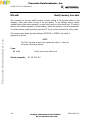
ASM addr [mne|dir]........................................................................................................... 3-5
BAUD [rate]...................................................................................................................... 3-7
BF addr1 [addr2] byte|word............................................................................................... 3-8
BL..................................................................................................................................... 3-9
BR [addr [macroname]]................................................................................................... 3-10
CALL addr...................................................................................................................... 3-11
CLRM............................................................................................................................. 3-12
CLS................................................................................................................................. 3-13
CONTROL [parameter]................................................................................................... 3-14
DASM addr1 [addr2]....................................................................................................... 3-15
DB startaddr [endaddr].................................................................................................... 3-16
DEBUG........................................................................................................................... 3-17
DEFINE symbol value|address......................................................................................... 3-18
DEFM macrnam|TRACE|AUTOSTART ......................................................................... 3-19
DELM macrnam|TRACE|AUTOSTART......................................................................... 3-21
DIR [mask]...................................................................................................................... 3-22
DOS [command].............................................................................................................. 3-23
EDITM macrnam............................................................................................................. 3-24
EEPROM [startaddr [endaddr]]....................................................................................... 3-25
EEPROM DELAY option ............................................................................................... 3-26
EEPROM ERASE [option] [addr]................................................................................... 3-27
EPROM [startaddr [endaddr]] ......................................................................................... 3-28
EPROM DELAY option.................................................................................................. 3-29
FIND byte|word addr1 addr2........................................................................................... 3-30
FIND mnemonic addr1 addr2........................................................................................... 3-31
G [addr]........................................................................................................................... 3-32
HELP [command]............................................................................................................ 3-33
KLE ................................................................................................................................ 3-34
LOADM [filename [macroname]].................................................................................... 3-35
LOADS filename [loadaddr] ............................................................................................ 3-36
LS symbol ....................................................................................................................... 3-37
LSTM [mname|TRACE|AUTOSTART].......................................................................... 3-38
MD startaddr [endaddr]................................................................................................... 3-39
MM addr......................................................................................................................... 3-40
MOVE addr1 addr2 addr3............................................................................................... 3-41
MS addr byte|word [byte|word] ....................................................................................... 3-42
Frees
cale Semiconductor,
I
Freescale Semiconductor, Inc.
For More Information On This Product,
Go to: www.freescale.com
nc...

CONTENTS
M68PCBUG11/D v
CHAPTER 3 USING PCBUG11 COMMANDS (continued)
MSG [string] ................................................................................................................... 3-43
NOBR [address].............................................................................................................. 3-44
PAUSE [mS]................................................................................................................... 3-45
PRINT............................................................................................................................. 3-46
PROTECT [startaddr [endaddr]] ..................................................................................... 3-47
QUIT [Y]........................................................................................................................ 3-48
RD [T] ............................................................................................................................ 3-49
RESET [addr] ................................................................................................................. 3-50
RESTART [option]......................................................................................................... 3-52
RM.................................................................................................................................. 3-53
RS register value.............................................................................................................. 3-54
S...................................................................................................................................... 3-55
SAVEM [filename].......................................................................................................... 3-56
SHELL [command] ......................................................................................................... 3-57
T [addr]........................................................................................................................... 3-58
TERM [X1 Y1 X2 Y2].................................................................................................... 3-59
TYPE filename ................................................................................................................ 3-60
UNDEF symbol............................................................................................................... 3-61
VER................................................................................................................................ 3-62
VERF filename [memaddr] .............................................................................................. 3-63
VERF ERASE addr1 [addr2]........................................................................................... 3-64
VERF SET addr1 addr2 value ......................................................................................... 3-65
WAIT [mS]..................................................................................................................... 3-66
CHAPTER 4 ADVANCED TOPICS
4.1 INTRODUCTION............................................................................................................. 4-1
4.2 MACROS.......................................................................................................................... 4-1
4.2.1 Defining Macros ....................................................................................................... 4-2
4.2.1.1 Autostart Macros............................................................................................. 4-3
4.2.1.2 Null Macros..................................................................................................... 4-3
4.2.2 Editing Macros ......................................................................................................... 4-3
4.2.3 Listing and Clearing Macros...................................................................................... 4-4
4.3 USING TRACE AND BREAKPOINTS............................................................................ 4-4
4.3.1 Breakpoints............................................................................................................... 4-4
4.3.2 Tracing ..................................................................................................................... 4-6
4.4 TALKERS IN EEPROM OR EXTERNAL MEMORY..................................................... 4-6
4.5 PROGRAMMING EPROM (711) PARTS........................................................................ 4-8
4.6 DESIGNING NEW TALKERS......................................................................................... 4-9
Frees
cale Semiconductor,
I
Freescale Semiconductor, Inc.
For More Information On This Product,
Go to: www.freescale.com
nc...

CONTENTS
vi M68PCBUG11/D
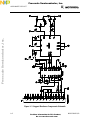
APPENDIX A HARDWARE SUPPORT
A.1 INTRODUCTION............................................................................................................A-1
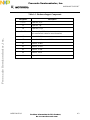
A.2 CIRCUIT DIAGRAM AND COMPONENTS LIST........................................................A-1
APPENDIX B PCBUG11 ERROR MESSAGES
B.1 INTRODUCTION............................................................................................................B-1
B.2 FAILED OPERATION ERRORS.....................................................................................B-1
B.3 COMMUNICATIONS ERRORS AND OTHER FATAL ERRORS ................................B-4
B.4 COMMAND ERRORS.....................................................................................................B-6
B.5 VERIFICATION ERRORS ..............................................................................................B-6
APPENDIX C PCBUG11 DISK CONTENTS
Frees
cale Semiconductor,
I
Freescale Semiconductor, Inc.
For More Information On This Product,
Go to: www.freescale.com
nc...

GENERAL INFORMATION
M68PCBUG11/D 1-1
CHAPTER 1
GENERAL INFORMATION
1.1 INTRODUCTION
M68HC11 PCbug11 is a software package for easy access to and simple experimentation with
M68HC11 microcontroller unit (MCU) devices. PCbug11 lets you program any member of the
M68HC11 MCU family and examine the behavior of internal peripherals under specific
conditions. In addition, you may run your own programs on the MCU; breakpoint processing and
trace processing are available.
This manual explains how to install and run PCbug11, version 3.24, as well as how to correct
common problems. (A user who has a later version of PCbug11 should check for any version
information notes attached to the end of this manual. Such notes contain information about any
changes from the information of the main text.)
Terminology conventions for this manual are:
• The acronym MCU denotes any member of the family of M68HC11 microcontroller
unit devices.
• Two-character, alphabetic and numerical codes denote specific MCUs. For example,
A8, D3, and E9 denote the MC68HC11A8, the MC68HC11D3, and the
MC68HC11E9, respectively.
• Monitor, or monitor program, is another term for PCbug11.
1.2 MCU SETUP FOR PCBUG11
Before you use an M68HC11 MCU with PCbug11, you must prepare hardware support
components and install the software on an IBM PC or compatible personal computer. For
information on hardware components, consult Appendix A.
Motorola supplies the software on a 360-Kbyte, IBM PC compatible master disk. You must
install this software on the hard disk of your computer, per paragraph 1.2.1.
Optionally, if your computer does not have a hard disk, you may run PCbug11 from
a flexible disk, per paragraph 1.2.2.
Frees
cale Semiconductor,
I
Freescale Semiconductor, Inc.
For More Information On This Product,
Go to: www.freescale.com
nc...

GENERAL INFORMATION
1-2 M68PCBUG11/D
1.2.1 Hard Disk Installation
In these instructions, drive A is the flexible disk drive and drive C is the hard disk. Follow these
steps to install the software on a hard disk:
1. Insert the master disk in drive A.
2. Make drive C the default drive (if it is not so already) by typing
C: [RETURN]
3. Create a new subdirectory by typing
md \PCBUG11 [RETURN]
4. Make this new subdirectory the default byt typing
cd \PCBUG11 [RETURN]
5. Copy all the files from the master disk to the hard disk by typing
copy a:*.* c: [RETURN]
This completes software installation. You may run PCbug11 from anywhere in the hard-disk
directory structure by using the DOS PATH command to include the C:\PCBUG11 subdirectory
in your path. (See DOS documentation for details on the PATH command.)
1.2.2 Flexible Disk Installation
These instructions are for a computer that has two flexible disk drives. Drive A is a 360-Kbyte
flexible disk drive. Drive B is the second flexible disk drive. You need a freshly formatted disk,
which will become your work disk.
Follow these steps to install the software:
1. Insert the master disk in drive A.
2. Insert the formatted disk in drive B. This disk becomes your work disk.
3. Copy all the files from the master disk to the work disk by typing
copy a:*.* b: [RETURN]
4. Remove the master disk from drive A.
5. Remove the work disk from drive B and insert it in drive A.
This completes software installation. You may run PCbug11 from the work disk in drive A.
Frees
cale Semiconductor,
I
Freescale Semiconductor, Inc.
For More Information On This Product,
Go to: www.freescale.com
nc...

GENERAL INFORMATION
M68PCBUG11/D 1-3
1.3 STARTING PCBUG11
To start the software package, set up the hardware, connect the hardware to the
computer communication port, and run the PCbug11 monitor program.
1.3.1 Running the Software
PCbug11 is sophisticated software that takes many possible options. The computer port used, the
crystal used, and any macros used determine which options are possible for a specific MCU.
To run the software, enter the startup command. The simplest run command is for an
MC68HC11A8, MC68HC11A1, or MC68HC11A0 MCU, with the XIRQ and PD0 pins
connected:
PCBUG11
-
XA
To run other MCUs of the M68HC11 family, alter the final one or two characters of this run
command, per Table 1-1. (As most M68HC11 MCUs have E9 type bootloaders, the
-XE
option
is the more frequently appropriate.) An X in the run command means that the XIRQ and PD0
pins must be connected (do not use the X option if PCbug11 is used with an EVBU board).
NOTE
The default number base of PCbug11 is 10. To change the default
base to 16, enter the command CONTROL BASE HEX. To
change the default base to 2, enter the command CONTROL
BASE BIN. To change the default base back to 10, enter the
command CONTROL BASE DEC. The CONTROL command
explanation, in Chapter 3, gives more information.
Frees
cale Semiconductor,
I
Freescale Semiconductor, Inc.
For More Information On This Product,
Go to: www.freescale.com
nc...

GENERAL INFORMATION
1-4 M68PCBUG11/D
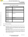
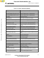
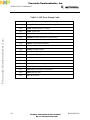
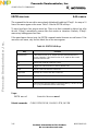
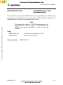
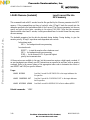
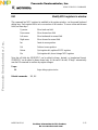
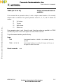
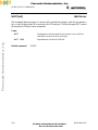
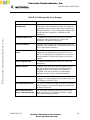
Table 1-1. PCbug11 Run Commands
MCU RUN Command
MC68HC11A0,
MC68HC11A1, or
MC68HC11A8
PCBUG11 -A
or
PCBUG11 -XA
MC68HC811A8
PCBUG11 -88
MC68HC11D3 or
MC68HC711D3
PCBUG11 -D
MC68HC11E0,
MC68HC11E1,
MC68HC11E9,
MC68HC11E20,
MC68HC11F1,
MC68HC11G5,
MC68HC11G7,
MC68HC11L6, or
MC68HC811A2
PCBUG11 -E
or
PCBUG11 -XE
MC68HC11E2
PCBUG11 -XA
MC68HC711E9
PCBUG11 -E
MC68HC11K4,
MC68HC711K4,
MC68HC11N4, or
MC68HC11P2
PCBUG11 -K
1.3.2 Monitor Screen Windows
Hardware status appears on the computer screen. This screen consists of four major areas, or
windows:
1. Main window. This window is the upper half of the screen. If you have a color screen,
the main window has white text on a blue background. This window displays the most
information about PCbug11 operation: command results, memory contents, assembly
opcodes, macros, and so forth.
2. Register window. This window is in the center of the screen. If you have a color
screen, the register window has white or yellow text on a red background. This
window shows the last recorded contents of the processor registers. Note that register
window values update only upon startup or user request. PCbug11 commands let you
modify the contents of the registers.
Frees
cale Semiconductor,
I
Freescale Semiconductor, Inc.
For More Information On This Product,
Go to: www.freescale.com
nc...

GENERAL INFORMATION
M68PCBUG11/D 1-5
3. Status window. This window is at the center right of the screen. If you have a color
screen, the status window has white text on a purple background. This window shows
the MCU in use; the MCU state (running, stopped, tracing); the status of the RS232
RTS line, and the current user-set interrupt vectors.
4. Command window. This window is at the bottom left of the screen. If you have a
color screen, the command window has white text on a black background. Use this
window for entering and reading commands to PCbug11. The command cursor (the »
character) is at the bottom line of this window; commands you enter appear after the
command cursor. Previous commands and the latest error message also appear in the
command window.
If your screen does not show these windows, the program is not running correctly. A DOS error
message or a PCbug11 error message indicates the problem. See paragraph 1.3.3 or Appendix B
for guidance on corrective action. If your screen does show these four windows, proceed to
paragraph 1.3.4 to try some simple commands.
There are two additional, temporary windows, which appear superimposed over the
main window:
1. Error window. This window indicates any errors or incorrectly operating
communications to the MCU. If you have a color screen, the error window has red
text on a black background. To clear the error window immediately, press any key.
(Or wait five seconds and the error window clears itself.)
2. Help window. This window displays help information requested via the HELP
command. If you have a color screen, the help window has white text on a black
background. To scroll through the help information, use the up-arrow, down-arrow,
page-up, and page-down keys. To clear the help window, press the ESC key.
1.3.3 Fixing Simple Problems
If the software did not start up correctly, the register screen shows rows of characters X instead
of values, and one or more error messages appear in the command window. Appendix B explains
the full meaning of such an error message.
Frees
cale Semiconductor,
I
Freescale Semiconductor, Inc.
For More Information On This Product,
Go to: www.freescale.com
nc...

GENERAL INFORMATION
1-6 M68PCBUG11/D
In the case of an initial startup, however, the most likely problems are a poor communications link
or an incorrect hardware setting. Make sure that:
• A 5-volt signal is supplied correctly to the user hardware.
• An 8 MHz crystal is installed in the circuit.
• The communications cable is wired correctly.
• The MCU is in bootstrap mode and is reset.
• The cable is connected to the COM1 port of the computer (or the guidance of
paragraph 2.2 is followed if the cable is connected to the COM2 port).
After checking these items, try again to start the system. If numerical values appear in the register
window and there are no error messages, PCbug11 is working correctly. Proceed to the simple
commands of paragraph 1.3.4.
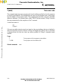
1.3.4 Trying Simple Commands
This paragraph explains a few simple commands that demonstrate PCbug11 operation. (Paragraph
3.2 explains the full PCbug11 command set.)
<CTRL>R This command tests communications between the user hardware and the
computer. If communications are operating correctly, the response
Communications synchronized
appears in the main window. Otherwise, the response
Communications fault
appears in the main window.
RESTART This command reloads the communications program and starts afresh, so it
is appropriate any time there is an indication of a communications fault. Be
sure to reset the MCU before typing in RESTART. Note, however, that
this command may lead to the loss of any program in processor RAM.
QUIT This command terminates a PCbug11 session. After you type in QUIT, a
message requests confirmation that you really do want to end the session.
Respond affirmatively, and the session ends.
RD This command displays register contents, letting you read the values.
Should rows of the character X appear instead of values, an error message
identifies the problem.
Frees
cale Semiconductor,
I
Freescale Semiconductor, Inc.
For More Information On This Product,
Go to: www.freescale.com
nc...

GENERAL INFORMATION
M68PCBUG11/D 1-7
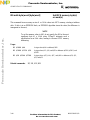
MD start_address (end_address) This command displays contents of
memory, from the start address through the end address. If you do not
enter the optional end address, PCbug11 displays the contents of the 16
memory locations beginning with the start address. Memory contents
appear in the main window. (If the address values consist only of digits, the
monitor considers them decimal numbers. To specify binary or hexadecimal
addresses, start them with the % or $ character, respectively.)
CLS This command clears the main window.
HELP (command) This command is valid only if you have installed the help file. Enter HELP
command by itself to see a summary of PCbug11 commands. Enter HELP
followed by another command to see specific help information on the other
command.
1.4 HOW PCBUG11 WORKS
PCbug11 works differently from most other microcomputer emulators or trainers. Other
emulators run sophisticated programs that communicate with a terminal. Such a program lets the
user execute programs, alter registers, and so forth, but requires a complex hardware platform.
The PCbug11 design, however, takes advantage of the sophistication of the PC. The
microcomputer need run only a simple program, so the hardware platform also can be simple.
PCbug11 carries out emulator functions via serial communication with the PC.
The monitor communicates with the MCU through a low-level program called a talker. PCbug11
includes different talkers to support different MCUs and different operating modes. All talkers
communicate between the SCI port of the MCU and the serial port of the PC. Each talker
occupies less than 256 bytes of MCU memory space and operates under interrupt. Some talkers
use internal MCU RAM: this approach is the boot method. Other talkers use internal EPROM or
other ROM: this approach is the ROMed method.
In the boot method, the PC downloads the talker into MCU internal RAM for each PCbug11
startup. Such a download happens via the special bootstrap mode of the MCU. In this mode, the
MCU automatically can download a program into its internal RAM and then run the program.
This makes it possible to alter internal values, program memory, read and write to chip ports, and
perform other functions. This simple approach requires no external hardware except a power
supply, an oscillator, and an RS-232C interface. The limitation of the boot method is its use of
about 240 bytes of internal RAM, which may be a problem for some users.
In the ROMed method, the PC synchronizes communication with a talker already running on the
MCU. This means that the appropriate talker must be programmed into internal or external MCU
memory before the user runs PCbug11. The simplest example of using the ROMed method is
placing the talker in external memory and running the talker every time the MCU is powered up.
If the talker is loaded into the MCU's internal EEPROM, no external memory is required.
Frees
cale Semiconductor,
I
Freescale Semiconductor, Inc.
For More Information On This Product,
Go to: www.freescale.com
nc...

GENERAL INFORMATION
1-8 M68PCBUG11/D
As a talker is interrupt driven, residing in the same memory map as user software, the RESET,
XIRQ, and SWI vectors must be reserved for talker code. Note, however, that the SCI vector
may be used instead of the XIRQ vector, to give maskable control to PCbug11.
The PCbug11 design leads to these rules of thumb:
1. If the PCbug11 is in boot mode, MCU internal RAM contains the talker program,
bootstrap-mode interrupt vectors, and the program stack. For an MCU that has 256
bytes of RAM, this leaves little room for user programs. In such a case, the user
should use EEPROM space for programs.
2. PCbug11 is interrupt driven, so the user must consider carefully any program that uses
interrupts or changes interrupt vectors. In the standard approach, the XIRQ pin causes
an interrupt whenever the user needs communications. This gives the user reasonably
free use of interrupts that set the I bit. But the user must be careful when using
breakpoint or trace operations, which also set the I bit. The user also must protect the
interrupt vectors from alteration; changes to these vectors cause loss of
communication with the program.
3. PCbug11 implements trace and breakpoint operations by placing a software interrupt
at the trace or breakpoint location. This means that PCbug11 must be able to modify
the code at such locations: the code must be in (internal or external) RAM or
EEPROM. The monitor cannot operate trace or breakpoints in ROM. This restriction
also applies to FLASH memory, which is not byte programmable. Note that PCbug11
makes use of a little software overhead to handle correctly any user-defined SWI.
(Breakpoints and tracing are not available with D3 or D0 MCUs.)
Frees
cale Semiconductor,
I
Freescale Semiconductor, Inc.
For More Information On This Product,
Go to: www.freescale.com
nc...

USING PCBUG11 SOFTWARE
M68PCBUG11/D 2-1
CHAPTER 2
USING PCBUG11 SOFTWARE
2.1 INTRODUCTION
This chapter introduces the user to several possibilities for using PCbug11 software. This
discussion also covers the runtime command structure and common pitfalls to avoid.
2.2 PCBUG11 RUNTIME COMMAND STRUCTURE
To use PCbug11, enter the runtime command at the DOS prompt. The syntax for this command
is:
PCBUG11 [[?]|[[-[X][talker]|[talker]][macro=macroname(params)][baud=baudrate] [port=1|2]]
Table 2-1 is the key to runtime command symbols and parameters.
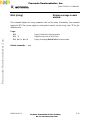
2.2.1 The <baudrate> Parameter
If your circuit uses an 8 MHz crystal, the standard for PCbug11, do not use the <baudrate>
parameter in the runtime command. In this case, the PC communications rate is 9600 baud, and
the download rate for a -<name> talker is 7812 baud.
For a circuit that uses an alternative crystal, the <baudrate> parameter is required:
• For a <boottype> talker, the <baudrate> value is the download rate for the talker. This
value must be to 7812 as the frequency (in MHz) of your crystal is to 8. That is,
<baudrate> = * 7812
crystal used MHz
8
• For a <ROMtype> talker, the <baudrate> value is the communications rate for the PC
and MCU. This value must be to 9600 as the frequency (in MHz) of your crystal is to
8. That is,
<baudrate> = * 9600
crystal used MHz
8
Frees
cale Semiconductor,
I
Freescale Semiconductor, Inc.
For More Information On This Product,
Go to: www.freescale.com
nc...

USING PCBUG11 SOFTWARE
2-2 M68PCBUG11/D
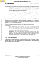
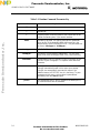
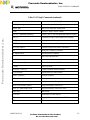
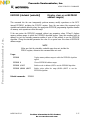
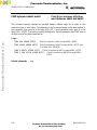
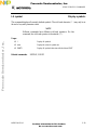
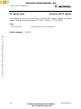
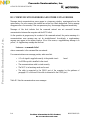
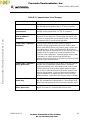
Table 2-1. Runtime Command Parameter Key
Symbol or Parameter Explanation or Role
[ ]
Enclose optional parameters.
|
Indicates
or
.
?
The query option. Enter this option to see a short form of the
runtime command syntax, if you need a reminder.
talker
The talker to be used. If a hyphen precedes this parameter
value, the file TALK<boottype>.BOO/.XOO must be in the
same directory as the file PCBUG11.EXE. This parameter has
two forms,
<boottype>
or
<ROMtype>
.
<boottype> A
,
D
,
E
,
K
,
88
, or
<userdefined>
<ROMtype>
The name of a user-defined ROMed talker. The user must
supply a file called <ROMtype>.MAP in the current directory.
<baudrate>
The baudrate for the PC and MCU if your circuit does not use
an 8 MHz crystal. Paragraph 2.2.1 explains more about this
parameter.
<macroname>
The name of a macro library file, such as <macroname>.MCR.
PCbug11 automatically loads such a macro upon startup.
PCbug11 also automatically executes this macro if the
additional macro AUTOSTART also is in the library. To pass
parameters to this macro, enclose them in parentheses
immediately after the
macro=
option.
port=2
The command to use PC port 2, instead of the default port 1,
for communications with the hardware.
Frees
cale Semiconductor,
I
Freescale Semiconductor, Inc.
For More Information On This Product,
Go to: www.freescale.com
nc...

USING PCBUG11 SOFTWARE
M68PCBUG11/D 2-3
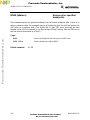
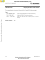
2.2.2 Runtime Command Examples
Some examples of the PCbug11 runtime command are:
PCBUG11 Entering the runtime command without any options invokes the command
line compiler. This lets the user input option information by answering a
series of prompts instead of making option information part of the runtime
command. This form of the runtime command may be appropriate if you
convert from one MCU to another or if you try a new option.
PCBUG11 ? Entering the runtime command with the query option tells the monitor to
display a short form of the runtime command syntax.
PCBUG11 -E This form of the runtime command runs the boot option talker for an MCU
of the M68HC11E, F, G, or L series. The monitor program downloads the
talker to RAM, then runs the talker.
PCBUG11 -XA port=2 This form of the runtime command runs the boot option talker for
an M68HC11A8, A1, A0, or E2 MCU, using PC port 2 (if port 2 exists).
The monitor program downloads the talker to RAM, then runs the talker.
PCBUG11 -XE macro=TRYIT This form of the runtime command runs the boot option
talker for an MCU of the M68HC11E, F, G, or L series and also loads the
macro TRYIT.MCR. If the AUTOSTART macro is in the macro library,
TRYIT execution begins automatically. (Paragraph 4.2 gives more
information about macros.)
PCBUG11 TALKEREE baud=4800 macro=LISTIT (1 2 3) For this form of the runtime
command, the talker TALKEREE already must be loaded in the MCU. The
value 4800 is the PC-to-MCU communications rate that corresponds to a 4
MHz crystal. This command also loads the macro LISTIT.MCR and passes
the parameters 1 2 3. (Note that for correct operation of this talker,
PCbug11 must be able to load the file TALKEREE.MAP, which contains
necessary system variables. TALKEREE.MAP must be in the user's current
working directory. Paragraph 4.4 explains more details.)
2.3 USES OF THE SOFTWARE
Possible uses for the PCbug11 software are unlimited. Note that the PCbug11 is not a software
simulation of an MCU; commands and programs you enter run on the real hardware, although via
a software interface. Most of the time the hardware runs the MCU in special bootstrap mode, so
access to secured resources is at user discretion, not under MCU control.
As the package runs under interrupt, it is possible to have a program running, but still be able to
read registers, write to registers, and even write to memory. A careful user can even modify the
Frees
cale Semiconductor,
I
Freescale Semiconductor, Inc.
For More Information On This Product,
Go to: www.freescale.com
nc...

USING PCBUG11 SOFTWARE
2-4 M68PCBUG11/D
program being run. Note that during modification of a program or registers, the running program
waits for processing of the interrupt caused by PCbug11.
You may set breakpoints in the software, so the MCU stops whenever it reaches that point in the
code. The trace command lets you step through code to examine the execution of instructions,
and see the results in registers and in the condition code register (CCR).
PCbug11 lets the user modify and assemble code into EEPROM as if it were RAM. Although the
MCU has an elaborate routine for programming this memory, PCbug11 handles such
programming in a manner transparent to the user. To make this possible, the user must first use
the EEPROM command to define the area of internal EEPROM. Do not, however, specify
external EEPROM in this way, as the talker automatically handles slow external memories. There
is a significant difference in response times between writing to EEPROM and writing to RAM.
2.4 PITFALLS TO AVOID
Some MCUs have a register that increases EEPROM protection. This is the BPROT register,
which usually is at address $1035. Before either the EEPROM or the CONFIG register can be
programmed, the BPROT register must be modified. Note that PCbug11
does not
modify the
BPROT register.
If you program the CONFIG register, remember that the contents of this register usually are not
readable until after MCU reset. Note that if the MCU is reset in bootstrap mode, certain
automatic functions place the part in an appropriate operating mode. If the MCU has a security
mode, clearing the NOSEC bit protects the internal RAM, internal EEPROM, and the internal
CONFIG register. This means that if the part is reset in bootstrap mode, the value of the NOSEC
bit will be 1.
Follow these guidelines to use interrupts with the hardware. Real-time and other such interrupts
are permitted when the I bit (RTII for the real-time interrupt) is clear and the appropriate
interrupt mask is set. An interrupt sets the interrupt I flag. A CLI or RTI instruction clears this
flag; note however, that the flag for an interrupt source remains set. For a real-time interrupt, this
is RTIF; an exit from a real-time interrupt service routine that leaves RTIF set causes another
interrupt immediately. This means that communications with PCbug11 could stop making sense or
that communications could cease (due to stack overflow).
When real-time measurements or calculations are in progress, remember that reading registers or
memory causes interrupts that interfere with logical program operation. This could upset results,
generating wrong answers. Such wrong answers are particularly likely when the processor is
waiting for the logical value on a port pin to change before carrying out some action. If the
change occurs while PCbug checks the processor status, the change could be lost or upset.
Remember that the MCU does its own self-examination; this self-examination does not affect
programs that perform off-line calculations or other functions.
Frees
cale Semiconductor,
I
Freescale Semiconductor, Inc.
For More Information On This Product,
Go to: www.freescale.com
nc...

USING PCBUG11 SOFTWARE
M68PCBUG11/D 2-5
PCbug11 implements breakpoints and traces via software interrupts (SWIs). When program
execution arrives at a breakpoint, an interrupt is generated; the internal talker handles this
interrupt. If the user directly uses the SWI, the SWI vector is called. If the SWI is a true
breakpoint, the PC so informs the user. While this common emulator arrangement is effective, it is
limited to use with RAM or EEPROM; ROM does not accomodate breakpoints or traces. There
is another problem if you reset or restart the MCU while all breakpoints are still set: the SWIs
remain in memory (especially EEPROM), displacing other opcodes. To prevent such a situation,
either clear all breakpoints before resetting or restarting the MCU, or reload your code
immediately after a reset or restart.
In bootstrap mode, PCbug11 puts its talker in MCU internal RAM. Overwriting any of the talker
software could cause loss of operations or communications with the MCU. Accordingly, you
should not place any user code or data in the same area as the talker.
This rule applies as well to the interrupt vector area of RAM. Interrupt vectors are redirected
from bootstrap ROM; they indicate that communications are required. If the stack is not initialized
to a suitable value, the interrupt vectors could be altered accidentally. For example, if you
initialized the stack to $FF, the first interrupt vector received would overwrite the redirected
vectors, causing loss of communications with the MCU. (Disabling bootstap ROM also causes
communications to fail.)
You may cause problems if you put a G command in a macro, followed by other commands that
modify memory associated with the program. As there is no way to know where the program is in
its execution, a macro may modify memory before or during the program's memory operation.
(Remember that PCbug11 commands operate under interrupts that temporarily halt the program.)
For example, such a situation could change the correct order of value storage in a memory
location, leading to incorrect operation or inaccurate results. To prevent such a problem, do not
use the G command together with a memory modify command in macros.
Also note that different boot talkers initialize the stack to different values, according to the
availability of RAM. These default values are:
A: $EB D: $EB E: $1FF K: $1FF 88: $EB
Be careful about moving from one processor to another, when the stack pointer value is different.
Frees
cale Semiconductor,
I
Freescale Semiconductor, Inc.
For More Information On This Product,
Go to: www.freescale.com
nc...

USING PCBUG11 SOFTWARE
2-6 M68PCBUG11/D
Frees
cale Semiconductor,
I
Freescale Semiconductor, Inc.
For More Information On This Product,
Go to: www.freescale.com
nc...
Page is loading ...
Page is loading ...
Page is loading ...
Page is loading ...
Page is loading ...
Page is loading ...
Page is loading ...
Page is loading ...
Page is loading ...
Page is loading ...
Page is loading ...
Page is loading ...
Page is loading ...
Page is loading ...
Page is loading ...
Page is loading ...
Page is loading ...
Page is loading ...
Page is loading ...
Page is loading ...
Page is loading ...
Page is loading ...
Page is loading ...
Page is loading ...
Page is loading ...
Page is loading ...
Page is loading ...
Page is loading ...
Page is loading ...
Page is loading ...
Page is loading ...
Page is loading ...
Page is loading ...
Page is loading ...
Page is loading ...
Page is loading ...
Page is loading ...
Page is loading ...
Page is loading ...
Page is loading ...
Page is loading ...
Page is loading ...
Page is loading ...
Page is loading ...
Page is loading ...
Page is loading ...
Page is loading ...
Page is loading ...
Page is loading ...
Page is loading ...
Page is loading ...
Page is loading ...
Page is loading ...
Page is loading ...
Page is loading ...
Page is loading ...
Page is loading ...
Page is loading ...
Page is loading ...
Page is loading ...
Page is loading ...
Page is loading ...
Page is loading ...
Page is loading ...
Page is loading ...
Page is loading ...
Page is loading ...
Page is loading ...
Page is loading ...
Page is loading ...
Page is loading ...
Page is loading ...
Page is loading ...
Page is loading ...
Page is loading ...
Page is loading ...
Page is loading ...
Page is loading ...
Page is loading ...
Page is loading ...
Page is loading ...
Page is loading ...
Page is loading ...
Page is loading ...
Page is loading ...
Page is loading ...
Page is loading ...
Page is loading ...
Page is loading ...
Page is loading ...
Page is loading ...
-
 1
1
-
 2
2
-
 3
3
-
 4
4
-
 5
5
-
 6
6
-
 7
7
-
 8
8
-
 9
9
-
 10
10
-
 11
11
-
 12
12
-
 13
13
-
 14
14
-
 15
15
-
 16
16
-
 17
17
-
 18
18
-
 19
19
-
 20
20
-
 21
21
-
 22
22
-
 23
23
-
 24
24
-
 25
25
-
 26
26
-
 27
27
-
 28
28
-
 29
29
-
 30
30
-
 31
31
-
 32
32
-
 33
33
-
 34
34
-
 35
35
-
 36
36
-
 37
37
-
 38
38
-
 39
39
-
 40
40
-
 41
41
-
 42
42
-
 43
43
-
 44
44
-
 45
45
-
 46
46
-
 47
47
-
 48
48
-
 49
49
-
 50
50
-
 51
51
-
 52
52
-
 53
53
-
 54
54
-
 55
55
-
 56
56
-
 57
57
-
 58
58
-
 59
59
-
 60
60
-
 61
61
-
 62
62
-
 63
63
-
 64
64
-
 65
65
-
 66
66
-
 67
67
-
 68
68
-
 69
69
-
 70
70
-
 71
71
-
 72
72
-
 73
73
-
 74
74
-
 75
75
-
 76
76
-
 77
77
-
 78
78
-
 79
79
-
 80
80
-
 81
81
-
 82
82
-
 83
83
-
 84
84
-
 85
85
-
 86
86
-
 87
87
-
 88
88
-
 89
89
-
 90
90
-
 91
91
-
 92
92
-
 93
93
-
 94
94
-
 95
95
-
 96
96
-
 97
97
-
 98
98
-
 99
99
-
 100
100
-
 101
101
-
 102
102
-
 103
103
-
 104
104
-
 105
105
-
 106
106
-
 107
107
-
 108
108
-
 109
109
-
 110
110
-
 111
111


Ask a question and I''ll find the answer in the document
Finding information in a document is now easier with AI
Related papers
Other documents
-
Fly B600 Hard reset manual
-
 Enabling Devices 5022 User manual
-
Freescale Semiconductor M68HC12A4EVB User manual
-
 TotalPass B600 Quick start guide
-
-
-
 Xantrex ACCB User manual
-
Intel SIM4-02 User manual
-
Xantrex Technology ACCB-L-L1 User manual
-
UVP DE-4 EPROM Erasing System Owner's manual


